Charging of a filter capacitor in the intermediate circuit of a frequency converter
US20050168897A1
2005-08-04
11/001,032
2004-12-02
✅ Patent granted
US 7,200,018 B2
2007-04-03
-
-
Bao Q. Vu
2025-04-25
Abstract:
A method and an apparatus for charging a filtering capacitor in the direct-voltage intermediate circuit of a voltage-controlled PWM frequency converter comprising a rectifier (20) connected to an alternating-current source (UR, US, UT), a direct-voltage intermediate circuit and an inverter unit (11)/inverter units for feeding a multi-phase alternating voltage (UU, UV, UW) of variable frequency into a load/loads (12), said rectifier bridge having controlled semiconductor switches (V1-V3), especially thyristors, in one arm, preferably in the upper arm, and diodes (D1-D6) in the other arm, preferably the lower arm, and said direct-voltage intermediate circuit being provided with a capacitor unit (CDC) of a relatively high capacitance for filtering the voltage. The filtering capacitor is charged by means of the semiconductor switches of the rectifier bridge by adjusting their firing angle according to the measured voltage of the capacitor unit, and the firing angle is adjusted by forming the sum of the measured voltage (UDC) of the capacitor unit and a predetermined limit voltage (ULIM) and comparing the said sum to the measured main voltages of the supply network.
Assignee:
- VACON OYJ 49 🇫🇮 Vaasa, Finland
Interested in similar patents?
Get notified when new applications in this technology area are published.
Classification:
H02M7/68 IPC
Conversion of ac power input into dc power output; Conversion of dc power input into ac power output with possibility of reversal by static converters
H02M7/04 IPC
Conversion of ac power input into dc power output; Conversion of dc power input into ac power output; Conversion of ac power input into dc power output without possibility of reversal by static converters
H02M5/458 » CPC main
Conversion of ac power input into ac power output, e.g. for change of voltage, for change of frequency, for change of number of phases with intermediate conversion into dc by static converters using discharge tubes or semiconductor devices to convert the intermediate dc into ac using devices of a triode or transistor type requiring continuous application of a control signal using semiconductor devices only
H02M5/271 » CPC further
Conversion of ac power input into ac power output, e.g. for change of voltage, for change of frequency, for change of number of phases without intermediate conversion into dc by static converters using discharge tubes with control electrode or semiconductor devices with control electrode using devices of a thyratron or thyristor type requiring extinguishing means for conversion of frequency from a three phase input voltage
H02M1/32 » CPC further
Details of apparatus for conversion Means for protecting converters other than automatic disconnection
Description
The present invention relates to a method and an apparatus for charging a filter capacitor in the intermediate circuit of a voltage-controlled PWM frequency converter.
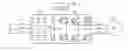
In PWM-frequency converters (frequency converters controlled by pulse-width modulation), a three-phase alternating voltage (phase voltages UR, US, UT) of a supply network is rectified in a rectifier unit (rectifier bridge 10, FIG. 1), the direct voltage UDC produced is filtered by means of a relatively large capacitor unit CDC and finally an alternating voltage (phase voltages UU, UV, UW) of desired frequency and magnitude is produced in an inverting or inverter unit (inverter bridge 11). The rectifier and inverter units may be mechanically separate from each other and the same rectifier unit can supply several inverter unit. The frequency converter may feed e.g. a three-phase cage induction motor (M) 12.
The rectifier bridge is typically either a non-controlled full-wave bridge, consisting of diodes (FIGS. 1 and 2), or a half-controlled bridge, consisting of thyristors and diodes (FIGS. 3 and 4).
Due to the large capacitor unit, the frequency converter can not be connected directly to the supply network, but the capacitors have to be first charged almost to their final voltage to avoid a large switching current surge. According to prior art, the charging of the capacitors is generally implemented by using a charging resistor e.g. as illustrated in FIGS. 2 and 3.
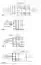
In the method according to FIG. 2, the rectifier circuit is a diode bridge and the charging occurs via a contactor K1 and a charging resistor R1. The contactor is connected to two phases of the circuit feeding the frequency converter. In an initial situation, the contactor is open and the intermediate circuit capacitor CDC is charged via the charging resistor R1 and the diode bridge. Once the intermediate circuit has been charged to a sufficient level, a control unit closes the contactor.
In the method according to FIG. 3, the rectifier circuit is a diode-thyristor bridge (thyristors V1-V3 in the upper arm and diodes D4-D6 in the lower arm). In this figure, the charging is described by way of example for the T phase only. In the other two phases, an identical circuit is used. In an initial situation, the relay K7 is in position 1 and a charging circuit is set up between supply phase uT and one of the other supply phases via the route D7-R7-K7-CDC-lower arm diode. Once the intermediate circuit has been charged to a sufficient level, the relay is turned to position 2, so the upper arm thyristor receives a firing pulse as soon as the corresponding phase voltage is more positive than the +terminal of the intermediate circuit. After this, the operation of the bridge corresponds to completely to the operation of a diode bridge.
The drawbacks of prior-art methods based on the use of a charging resistor include the following:
-
- the charging resistor is an extra component that has to be rated according to the intermediate circuit capacitance
- in the method according to FIG. 2, a contactor rated for the main circuit current is needed, and
- if the intermediate circuit is in a shorted condition in the initial situation, the charging resistor is destroyed in both methods, because for an economical rating it is only necessary to take into account the instantaneous dissipation required by the charging.
The object of the present invention is to overcome the drawbacks of prior art and achieve a charging arrangement of a new type. In the arrangement of the invention, the charging of the capacitors is performed in a thyristor bridge exclusively by controlling the firing angle of the thyristors. The features of the solution of the invention are presented in detail in the claims below.
As compared to traditional methods, the disclosed principle provides several advantages, such as:
-
- no charging resistor is needed at all,
- the magnitude of the intermediate circuit capacitance has no effect on the performance of the charging process,
- if several rectifier bridges are connected in parallel, the order in which they are connected to the mains has no importance, in other words, they can charge a common intermediate circuit either in parallel or separately,
- if the intermediate circuit is shorted, the charging current remains under control and nothing is destroyed, and
- the control principle is simple, so it can be implemented by a simple and economical control logic.
In the following, the invention will be described in detail with reference to an example and the attached drawings, wherein
FIG. 1 represents a prior-art voltage-controlled PWM frequency converter and a cage induction motor as its load,
FIG. 2 represents a prior-art method of charging the intermediate circuit by means of a charging resistor,
FIG. 3 represents another prior-art method of charging the intermediate circuit by means of a charging resistor,
FIG. 4 represents an embodiment of a rectifier circuit in which the charging method of the invention can be applied,
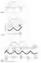
FIG. 5 represents the definition of firing angle in the charging method of the invention,
FIG. 6 represents the limit value voltage and the generation of a charging current pulse,
FIG. 7 represents the progress of the charging process by the method of the invention,
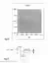
FIG. 8 presents an example of the limit value of the firing voltage, and
FIG. 9 illustrates the indication of the firing instant of the thyristors in the charging method of the invention.
In the charging method of the invention, the rectifier circuit used is a diode-thyristor bridge of the same type as in the prior-art solution (20, FIG. 4) illustrated in FIG. 3. The charging is implemented by adjusting the firing angle of the thyristors according to the measured intermediate circuit voltage in such manner that initially, when the intermediate circuit voltage UDC is low, the firing angle is very large, and as the intermediate circuit is getting charged, the firing angle is diminished according to the measured intermediate circuit voltage.
In the method of the invention, a pulsating charging current is used. To keep the current pulses under control, it is required, in addition to phase angle control, that a three-phase AC inductor LAC is connected between the mains and the rectifier circuit as shown in the example in FIG. 3 or that a DC inductor LDC is connected between the rectifier circuit and the filter capacitor of the direct-voltage circuit e.g. as shown in FIG. 4. Such inductors are used in prior art to limit mains current harmonics, and the use of the charging method of the present invention does not impose any additional requirements regarding the rating of the inductor. In the description of the invention, reference is made to an inductor solution as illustrated in FIG. 4 to make things more readily understandable, but the method works just as well with an AC inductor solution, as is obvious to the skilled person.
The firing angle of the diode-thyristor bridge is the angle after the earliest possible firing instant at which the thyristor is fired. For example, in FIG. 5 firing angle 0° (the earliest possible firing instant) of the R-phase thyristor V1 means instant t0, at which phase voltage UR becomes more positive than phase voltage uT. Correspondingly, firing angle 180° (the latest possible firing instant) corresponds to instant t180.
The adjustment of the firing angle is based on the voltage difference between the measured intermediate circuit voltage and the measured main voltage in the following manner:
-
- The thyristor is fired when the phase voltage measured against the DC potential (the phase voltage being the same as the main voltage because, due to the diodes D4-D6, the DC potential continuously follows the most negative phase voltage) falls below the predetermined limit value uLIM added to the measured intermediate circuit voltage UDC (FIG. 6). In the example in FIG. 6, such a situation occurs for phase T at instant t1, at which thyristor V3 is fired, and for phase R at instant t2, at which thyristor V1 is fired. When the thyristor is fired, there follows a current pulse whose amplitude is determined by the time integral of the voltage between the main voltage and the intermediate circuit voltage between the firing instant and the instant when the main voltage falls below the intermediate circuit voltage (shaded area between t2 and t3). This current pulse charges the intermediate circuit capacitor CDC and it ends due to the negative time interval between the main voltage and the intermediate circuit voltage (shaded area between t3 and t4).
- To keep the charging current pulses under control, the limit value ULIM of the voltage difference is a function of the intermediate circuit voltage, such that the limit value decreases as the intermediate circuit voltage rises. Reducing the limit value is an expedient for keeping the voltage area increasing the charging current constant, thus keeping the amplitude of the charging current pulse constant as well.
In the following, the method will be described in more detail.
The charging of the intermediate circuit under firing angle control progresses according to FIG. 7 as follows. The figure does not show the limit value curve ULIM.
-
- 1. Before instant t10
- the intermediate circuit voltage is 0
- the DC potential follows phase R, whose instantaneous value is the most negative
- 2. At instant t10
- The S-phase thyristor V2 is fired when the main voltage [uS-uR] falls below the limit value
- 3. Time interval t10-t11
- a charging current pulse is transmitted via phases S and R, charging the intermediate circuit capacitor
- 4. Time interval t11-t20
- UDc remains unchanged and the DC potential follows phase S, which is the most negative
- 5. At instant t20
- the main voltage [uT-uS] falls below the limit value, so the T-phase thyristor V3 is fired
- 6. Time interval t20-t21
- a charging current pulse passes via phases T and S, charging the intermediate circuit capacitor a little more
- 7. And so on. The charging process goes on in the above-described manner until UDC finally reaches the limit value at which the thyristors can be turned fully on.
- 1. Before instant t10
It is preferable to apply an arrangement whereby the charging current pulses become at least roughly equal according to the ratings of the main circuit components. Therefore, the voltage limit value below which the thyristor is fired is advantageously lowered as the intermediate circuit voltage rises (with a constant limit curve the charging current would increase with the progress of the charging process).
FIG. 8 presents an example case regarding this question. In the example, the peak value of the charging current pulse remains at a magnitude of 400 A when the limit value is adjusted according to the figure and the other main circuit values relevant to the charging are:
- Umains=400V
- Fmains=50 Hz
- LAC=70 μH/phase
- CDC=10 mF
In a practical implementation, the curve shown in the figure can be replaced by a straight line connecting the end points of the curve. This will only have the consequence that the charging current pulses are somewhat smaller in the intermediate range, which is why the charging process is a little longer. It is also possible to keep the limit value constant, in which case the charging current pulse will increase with the progress of the charging process.
An example circuit designed to apply the method is presented in FIG. 9 for phase R. The simplified thyristor control circuit comprises a comparator COMP1, one input of which is fed by the sum of the measured direct voltage UDC and the limit value ULIM and the other input is fed by the measured main voltage [uR-DC-]. Connected to the output of the comparator is a gate driver DRIVER V1, which controls the thyristor V1. The comparator output COMP1 rises up at instant t30 (FIG. 7) when the measured main voltage falls below the limit value level of the second input of the comparator.
Firing of the wrong thyristor (such as e.g. T-phase thyristor V3 within time interval t30-t40 in FIG. 7, during which the output of the comparator of this phase is high for part of the time) can be prevented e.g. by using a time delay that blocks all driving signals for a few ms after thyristor V1 has received a firing pulse.
It is obvious to the person skilled in the art that different embodiments of the invention are not limited to the example described above, but that they may be varied within the scope of the claims presented below.
Claims
1. A method for charging a filtering capacitor in the direct-voltage intermediate circuit of a voltage-controlled PWM frequency converter comprising
a rectifier (20) connected to an alternating-current source (UR, US, UT),
a direct-voltage intermediate circuit and
an inverter unit (11)/inverter units for feeding a multi-phase alternating voltage (UU, UV, UW) of variable frequency into a load/loads (12),
said rectifier bridge having controlled semiconductor switches (V1-V3), especially thyristors, in one arm, preferably in the upper arm, and diodes (D1-D6) in the other arm, preferably the lower arm, and
said direct-voltage intermediate circuit being provided with a capacitor unit (CDC) of a relatively high capacitance for filtering the voltage,
characterized in that, in the method,
the filtering capacitor is charged by means of the semiconductor switches of the rectifier bridge by adjusting their firing angle according to the measured voltage of the capacitor unit, and
the firing angle is adjusted by forming the sum of the measured voltage (UDC) of the capacitor unit and a predetermined limit voltage (ULIM) and comparing the said sum to the measured main voltages of the supply network.
2. A method according to claim 1,
characterized in that the firing angle is adjusted by using the voltage difference between the measured intermediate circuit voltage and the measured main voltage in such manner that each semiconductor switch, preferably thyristor, is fired when the value of the measured main voltage corresponding to it falls below the sum of the measured intermediate circuit voltage (UDC) and the predetermined limit value (ULIM).
3. A method according to claims 1 and 2,
characterized in that, to keep the charging current pulses under control, the limit value (ULIM) of the voltage difference is a function of the intermediate circuit voltage, such that the limit value decreases as the intermediate circuit voltage rises.
4. A method according to claims 1 and 2,
characterized in that the limit value (ULIM) is independent of the measured intermediate circuit voltage.
5. An apparatus for charging a filtering capacitor in the direct-voltage intermediate circuit of a voltage-controlled PWM frequency converter
said frequency converter comprising a control unit (13), a rectifier (20) connected to an alternating-current source (UR, US, UT),
a direct-voltage intermediate circuit and
an inverter unit (11)/inverter units for feeding a multi-phase alternating voltage (UU, UV, UW) of variable frequency into a load/loads (12),
said rectifier bridge having controlled semiconductor switches (V1-V3), especially thyristors, in one arm, preferably in the upper arm, and diodes (D1-D6) in the other arm, preferably the lower arm, and
said direct-voltage intermediate circuit being provided with a capacitor unit (CDC) of a relatively high capacitance for filtering the voltage,
characterized in that,
to charge the filtering capacitor, the control unit adjusts the firing angle of the semiconductor switches of the rectifier bridge according to the measured voltage of the capacitor unit in such manner that
the control unit measures the voltage (UDC) of the capacitor unit and adds to it a predetermined limit voltage (ULIM), and
the control unit adjusts the firing angle by comparing the said sum to the measured main voltages of the supply network.
6. An apparatus according to claim 5,
characterized in that the control unit adjusts the firing angle by using the voltage difference between the measured intermediate circuit voltage and the measured main voltage in such manner that each semiconductor switch, preferably thyristor, is fired when the value of the measured main voltage corresponding to it falls below the sum of the measured intermediate circuit voltage (UDC) and the predetermined limit value (ULIM).
7. An apparatus according to claims 5 and 6,
characterized in that the control circuit of the semiconductor switch comprises at least a comparator (COMP1), one input of which can be fed by the sum of the measured direct voltage (UDC) and the calculated limit value (uLIM) and the other input with the measured main voltage corresponding to the semiconductor switch, and a gate driver (DRIVER1) connected to its output.
8. An apparatus according to claims 5 and 6, characterized in that the control unit of the semiconductor switch employs a time delay to prevent firing the wrong thyristor, during which delay the firing of all the thyristors is prevented, said delay being given after each firing pulse.
Images & Drawings included:
Sources:
- United States Patent and Trademark Office - verify current appl. status at the USPTO↗
Recent applications in this class:
- » 20250274051 2025-08-28
MAGNETICALLY COUPLED CHARGING SYSTEM AND THE METHOD THEREOF - » 20250202378 2025-06-19
Configurable Drive System - » 20250158535 2025-05-15
DC BUS CAPACITOR ASSEMBLIES FOR VIENNA VFD IN AIR CONDITIONING SYSTEMS - » 20250158534 2025-05-15
POWER CONVERSION SYSTEM AND POWER UPDATE CONTROL METHOD - » 20250132688 2025-04-24
Voltage Driving Circuit and System and Household Appliance - » 20250030352 2025-01-23
VOLTAGE BOOST MODULE FOR A POWER CONVERTER - » 20240305211 2024-09-12
ARC FURNACLE FACILITY - » 20240275296 2024-08-15
CHARGING CURRENT METHOD, CHARGING CURRENT DEVICE, AND ELECTRONIC CONVERTER WITH THE CHARGING CURRENT DEVICE - » 20240235408 2024-07-11
HYBRID MODULAR MULTILEVEL RECTIFIER (HMMR) FOR HIGHLY DYNAMIC LOAD APPLICATIONS - » 20240097576 2024-03-21
DC POWER SUPPLY DEVICE, MOTOR DRIVING DEVICE, AND REFRIGERATION CYCLE APPLICATION APPARATUS
Recent applications for this Assignee:
- » 20150342076 2015-11-26
Housing arrangement of a power electronics device - » 20150340943 2015-11-26
Electric interference limitation - » 20150206041 2015-07-23
Arrangement for connecting set values concerning performance to an electronics device - » 20150171781 2015-06-18
PMSM rotor angle identification - » 20140305611 2014-10-16
Liquid cooling arrangement - » 20140304927 2014-10-16
INSTALLATION ARRANGEMENT FOR A POWER ELECTRONICS DEVICE - » 20140168897 2014-06-19
Power electronics device and its cooling arrangement - » 20140140005 2014-05-22
Power electronics device - » 20130121845 2013-05-16
Compressor starting method and apparatus - » 20120181955 2012-07-19
Transfer apparatus for electric power