Swing trainer
US20050170902A1
2005-08-04
11/016,273
2004-12-17
Abstract:
A swing trainer for use with golf or cricket practice comprises a shaft and oversized head. The shaft carries a frame provided with markings that allow virtual verification of the back swing, down swing and follow through. The trainer can also be provided with means such as a weight with a conduit, which slides within the conduit to emit a noise indicating a correct wing.
Interested in similar patents?
Get notified when new applications in this technology area are published.
Classification:
A63B69/3632 » CPC main
Training appliances or apparatus for special sports for golf for driving Clubs or attachments on clubs, e.g. for measuring, aligning
A63B69/3638 » CPC further
Training appliances or apparatus for special sports for golf for driving; Clubs or attachments on clubs, e.g. for measuring, aligning Normal golf clubs with directly attached weights
A63B69/3667 » CPC further
Training appliances or apparatus for special sports for golf Golf stance aids, e.g. means for positioning a golfer's feet
A63B2208/12 » CPC further
Characteristics or parameters related to the user or player specially adapted for children
Description
The present invention relates to swing trainers which may be used in the practice of swings such as the swing of a golf club or a cricket bat. The invention may also be applied to other activities where the arc of a swing is important such as racquet sports such as tennis, squash and badminton or in the casting of fishing lines.
In these types of activities the swing consists of a back swing a downward swing and in some instances a follow through. In the case of ball sports, the swing should follow the desired arc of swing to generate the required force and direction of impact on the ball. For many participants improvement of the arc of swing and the timing of the swing is important for any improvement in performance and thus practice is essential.
Many swing training devices are known such as the use of oversized heads for golf clubs and the like. However, we are not aware of any devices that enable the user to have a visual guide and/or audible emission to indicate the appropriate arc of the swing and to enable practice to improve such arc.
The present invention provides such a device. In particular the invention provides means to verify the appropriate position of the leading (front) arm during the back swing and to verify the arc of the downswing and follow through.
The present invention therefore provides a swing trainer comprising
-
- i. a head and a shaft
- ii. a frame for attachment to the shaft comprising
- a. means to enable visual verification of the back swing when the shaft is substantially parallel with the ground and
- b. means to enable visual verification of the back swing when the shaft has been swung back to about chest height.
- iii. one or more pointers adapted to contact the leading arm during the back swing
- iv. means capable of attachment to the shaft to enable visual verification of the arc of the down swing.
In a preferred embodiment the swing trainer of the invention includes means for visual verification that the head is directed towards the target at the bottom of the down swing.
The invention accordingly enables the user to verify the swing through the back swing, the down swing and the follow through and thus enables verification and practice of for instance a golf swing.
In a preferred embodiment means are also provided to enable visual verification of the follow through.
The trainer of the present invention preferably incorporates an oversized head and a frame attachment. The frame attachment may be any convenient shape, it may be triangular, circular, oval or any other suitable shape providing it can serve to provide the visual verification provided by the invention. In one embodiment the frame is A shaped and attached to both the head and shaft. A conventional steel or graphite shaft may be used equally any other material could be used to form a shaft. Any means may be used for attachment of the shaft to the head.
A grip is generally part of the shaft and any grip may be used although for golf it is preferred to use a shaped grip typically used for training.
The material used for the head is conveniently a foam board a type of plastic. It could equally be made of wood or mdf construction and is preferably between 5 and 40 centimeters long and has a depth of from 8 to 30 centimeters. We prefer to employ an ovoid shaped head. The optimum size and weight of the head will depend upon the user, for example a smaller, lighter head may be used for trainers for children than with trainers for adults.
In a preferred embodiment of the present invention a longitudinal conduit such as a tube containing a moveable weight is attached to or incorporated in the head. This provides an audible emission when the weight such as a ball bearing travels up and down the conduit during the swing. At the top of the back swing the weight slides down the conduit and on the down swing the weight slides to the opposite direction giving an audible sound. The conduit can be mounted so that the sound is produced when the club is swung slowly and in the correct angle. By adjusting the swing according to the emission of the sound the timing of the swing can be dramatically controlled and improved.
The attachment is preferably an A frame and the object of the A frame is to show the player the correct position and angle of the club during various phases of the swing. One or more pointers that point towards and can touch the rear shoulder of the leading arm and optionally elsewhere on the leading arm during and preferably at the top of the back swing to indicate that the back swing is correct. In a preferred embodiment the frame is provided with two or more such pointers which can contact the leading arm at or close to the wrist, elbow and shoulder at or close to the top of the back swing to indicate that the back swing is correct. Preferably the frame is provided with three such pointers.
The pointers are preferably attached to the frame and preferably at least one of the pointers is substantially perpendicular to the frame. We prefer that for ease of use, sections of the frame are of different colours according to the function the particular section serves although dark lines may be provided on a pale colour background to enable the required visible verifications.
The design and operation of the trainer is now described in relation to the accompanying drawings in which
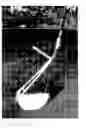
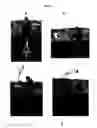
FIG. 1 shows a golf club with an oversized head.
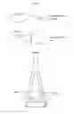
FIG. 2 shows a tube mounted on the frame and containing a weight.
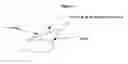
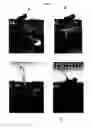
FIG. 3 shows the triangular attachment and how it may be split into two types of lines
-
- A black
- B yellow
These different colours are the key to checking certain positions during the swing.
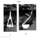
The A frame is attached to the club head or the nose of the head and may be attached to the shaft via a half sleeve that fits onto the shaft. See FIG. 4.
In operation the A frame may be used to monitor the back swing, the down swing and the follow through in the following manner.
The Back Swing
Movement 1
As a player starts his back swing on getting to the position of the shaft at waist height the shaft should be parallel with the player's feet and the short black line on the A frame should be horizontal to the ground and the pointer should be substantially perpendicular.
Movement 2
The arm is now at chest height and the short yellow line on the A frame should now be horizontal with the ground and the long yellow line should be perpendicular.
Movement 3
The player continues to lift his leading arm until he has hinge wrists and the pointer that is set at 90 degrees to the A Frame should point to the backward shoulder. If this pointer does not achieve that position then the player knows that the swing is not in the correct place. On this final point of the back swing, the audible sound of the movement of the weight in the conduit tells the player he has completed his back swing.
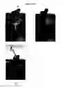
The back swing is illustrated in FIG. 5, d1 to d4
The Down Swing
Movement 4
The angle must be maintained between the shaft and the backhand arm on the down swing, until the short black line is horizontal and the shaft is substantially at waist height.
Movement 5
The movement is from the bottom of the down swing to the follow through and continues from shaft being horizontal on the back swing to horizontal on the follow through. The face of the club at impact must be square to the target, or at right angles to the target.
The Follow Through
When the shaft is at waist height in front of the body on the follow through the long black line on the A frame should point directly to the target. With the head in a vertical position the toe of the head will be pointing marginally to the right of the target, and at that point the backhand arm should be dead straight. The wrists then start to hinge the pointing bar, which must be pointing at all times to the backhand shoulder.
The down swing and follow through are illustrated in FIG. 6, ds1 to ds7.
The trainer of the present invention therefore enables practice to achieve the correct arc of swing and angles throughout the entire swing.
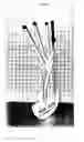
FIG. 7 shows a preferred embodiment of the present invention in which there are three pointers, one of which is substantially perpendicular to the frame. As FIG. 8 shows these three pointers can contact the leading arm close to or at the shoulder, elbow and wrist of the leading arm of the user at the top of the back swing to ensure a proper back swing.
Claims
1. A swing trainer comprising
a. a head and a shaft
b. a frame for attachment to the shaft comprising
i. means to enable visual verification of the back swing when the shaft is substantially parallel with the ground and
ii. means to enable visual verification of the back swing when the shaft has been swung back to about chest height.
c. one or more pointers adapted to contact the leading arm during the back swing
d. means capable of attachment to the shaft to enable visual verification of the arc of the down swing.
2. A swing trainer according to claim 1 in which at least one of the pointers is substantially perpendicular to the frame.
3. A swing trainer according to claim 1 provided with three pointers to contact the leading arm at or close to the wrist, elbow and shoulder at or close to the top of the back swing.
4. A swing trainer according to claim 1 including means for visual verification that the head is directed towards the target at the bottom of the down swing.
5. A swing trainer according to claim 1 including means to enable visual verification of the follow through.
6. A swing trainer according to claim 1 comprising an oversized head and a frame attachment.
7. A swing trainer according to claim 1 in which the frame attachment is A shaped
8. A swing trainer according to claim 1 in which the frame is circular.
9. A swing trainer according to claim 1 in which the head is between 5 and 40 centimeters long and has a depth of from 8 to 30 centimeters.
10. A swing trainer according to claim 9 in which the head is an ovoid shape.
11. A swing trainer according to claim 1 including a longitudinal conduit containing a moveable weight attached to or incorporated in the head.
12. A swing trainer according to claim 11 in which the conduit is mounted so that a sound is produced when the club is swung slowly and in the correct angle.
13. A swing trainer according to claim 1 in which the frame is provided with a pointer that points towards and can touch the rear shoulder at the top of back swing.
14. A swing trainer according to claim 1 in which the frame is provided with a pointer that points towards and can touch at or close to the elbow of the leading arm at the top of the back swing.
15. A swing trainer according to claim 1 in which the frame is provided with a pointer that points towards and can touch at or close to the wrist of the leading arm at the top of the back swing.
16. A swing trainer according to claim 1 in which sections of the frame are of different colors according to the function the particular section serves.
Images & Drawings included:
Sources:
- United States Patent and Trademark Office - verify current appl. status at the USPTO↗
Similar patent applications:
- » 20080207347
Golf swing trainer and method of improving a golf swing - » 20050261074
Golf swing trainer - » 20070155525
Golf swing trainer - » 20060105853
Golfer's audio aid swing trainer - » 20060135292
Baseball swing trainer - » 20060258476
METHOD OF MAKING A WEIGHTED GOLF SWING TRAINER - » 20060073903
Golf swing trainer - » 20070238541
Golf clubface swing trainer - » 20070238556
Tennis swing trainer - » 20050009617
Light-based golf swing trainer
Recent applications in this class:
- » 20250135314 2025-05-01
Swing Speed Training Device - » 20250128135 2025-04-24
SYSTEM AND METHOD FOR GOLF SUPER TAG MULTIFUNCTION GOLF SWING CAPTURE AND ANALYSIS DEVICE - » 20250065211 2025-02-27
APPARATUS AND METHOD FOR GOLF ALIGNMENT TRAINING - » 20240382819 2024-11-21
GOLF LESSON SYSTEM USING TACTILE STIMULATION AND GOLF LESSON METHOD USING THE SAME - » 20240350886 2024-10-24
GOLF SWING TRAINING DEVICE AND METHODS OF USE - » 20240299823 2024-09-12
Counterweighted Golf Club Swing Training Apparatus - » 20240226692 2024-07-11
GOLF SHOT TRACKING SYSTEM - » 20240189693 2024-06-13
Apparatus and method for golf alignment training - » 20240173604 2024-05-30
Swing motion trainer - » 20240001212 2024-01-04
GOLF TRAINER DEVICE