Rakh cycle engine
US20050172623A1
2005-08-11
10/979,087
2004-10-26
Abstract:
A new thermodynamic cycle engine consisting of six events repeated continuously. Event 1 is adiabatic compression of a carrier gas to raise its temperature. Event 2 is liquid Injection into the hot carrier gas near the end of event 1. Event 3 is temperature equalization between the carrier gas and injected liquid with the liquid's full or partial vaporization. Event 4 is adiabatic expansion of the mixture. Event 5 exhausts the mixture. Exhaust should be captured to save and separate the mixture into its components to increase efficiency. Event 6 is the induction of a new charge of carrier gas, bringing the cycle back to initial conditions of event one. This cyclical sequence of six events numbered from any starting point in an engine will be referred to as the RAKH CYCLE Engine. Devices reversing this cycle using compression to concentrate heat, and injecting water to cool the carrier gas are RAKH CYCLE Refrigerators.
Interested in similar patents?
Get notified when new applications in this technology area are published.
Classification:
F02B75/021 » CPC main
Other engines; Engines characterised by their cycles, e.g. six-stroke having six or more strokes per cycle
F01K25/06 » CPC further
Plants or engines characterised by use of special working fluids, not otherwise provided for; Plants operating in closed cycles and not otherwise provided for using mixtures of different fluids
F25B9/00 » CPC further
Compression machines, plants or systems, in which the refrigerant is air or other gas of low boiling point
Description
BACKGROUND OF INVENTIONIn researching the present invention, I discovered many patents that took advantage of waste heat to increase mechanical work and engine efficiency. Most of these patents selected water as the injected liquid. None of the other patents, however, made use of superheated injected liquids. The liquid entering a relatively low pressure cylinder when compared with the liquid's saturation pressure at the injected temperature is indeed superheated for an instant after being injected. The physical calculations of temperature and pressure show that the temperature of the injected liquid if water is the selected substance needs to be within a fairly close proximity to the critical temperature in order to increase pressure of the mixture. Water has such a high latent heat of vaporization that it can easily over cool the compressed gas and result in a decrease of pressure. No engine will be as efficient as it is without injecting water, if both temperature and pressure decrease before the power stroke begins expansion. Typically, in engine patents that I reviewed, ambient water was converted to steam using waste heat of combustion gasses. Each, typically, also used internal combustion from an Otto or Diesel cycle to generate the heat. The present invention does not use internal combustion for its heat source. A ‘carrier gas’ is heated outside the engine, via solar, a typical water heater, or exhaust recovery heat. A liquid is also pre-heated externally or by purchasing/renting an insulated, pressurized container of the hot liquid. The present invention is somewhat more like a battery powered motor than an internal combustion engine. Some combination of liquid and carrier gas should permit the use of ambient heating of the carrier gas while supplying a pressurized, stored ‘thermos’ of liquid heated to near its critical temperature as the only energy input necessary. Presently, the demonstrated RAKH Cycle Engine prefered configuration uses argon carrier gas with hot water as the injected liquid.
| References Cited |
| U.S. Patent Documents |
| 770468 | September, 1904 | Lake | 60/674 | |
| 917317 | April, 1909 | Lake | 60/674 | |
| 924100 | June, 1909 | Nichols | 123/191 | |
| 1032236 | July, 1912 | Patten | 60/650 | |
| 1739255 | December, 1929 | Niven | 123/193 | |
| 1926463 | September, 1933 | Stoddard | 60/650 | |
| 2062013 | November, 1936 | Opolo | 123/193 | |
| 2791881 | June, 1954 | Denker | 60/619 | |
| 3006146 | October, 1961 | Jackson | 60/649 | |
| 3867816 | February, 1975 | Barrett | 60/682 | |
| 3,964,263 | Jun. 22, 1976 | Tibbs | 60/712 | |
| 4,270,351 | Jun. 2, 1981 | Kuhns | 60/517 | |
| 4,322,950 | Apr. 6, 1982 | Jepsen | 60/712 | |
| 4,326,388 | Apr. 27, 1982 | McFee | 62/324.6 | |
| 4,402,193 | Sep. 6, 1983 | McFee | 62/304 | |
| 4,553,397 | Nov. 19, 1985 | Wilensky | 60/649 | |
| 4,691,523 | Sep. 8, 1987 | Rosado | 60/649 | |
| 5,035,115 | Jul. 30, 1991 | Ptasinski | 60/712 | |
| 5,983,640 | Nov. 16, 1999 | Czaja | 60/674 | |
The engine and its thermodynamic cycle, which is described herein, will be called the RAKH CYCLE ENGINE. The said engine cycle involves a gas or mixture of gasses that are herein referred to as the ‘carrier gas’ and a superheated liquid, which vaporizes but does not burn. The purpose of the carrier gas is to bring thermal energy into a volume where compression is used to concentrate thermal energy at a higher temperature. A liquid is then injected. In an engine cycle, the liquid must be superheated above its saturation temperature corresponding to the pressure that the carrier gas attains at its maximum compression. The carrier gas must be much hotter than the injected liquid in order to force heat to be transferred into the injected liquid rapidly. Heat that is transferred from the carrier gas will cool the carrier gas resulting in a lower temperature and pressure. Transfer of the heat from the carrier gas into the liquid, on the other hand, will greatly increase the volume of the injected liquid, through converting it into a vapor. The temperature of the liquid will increase while the temperature of the carrier gas will decrease. The decrease of temperature is moderated by further compression of the carrier gas due to displacement from the vapor produced forcing the carrier gas into a smaller volume. All of the experimental results, which I have derived by calculation, have always resulted in a lower temperature from the end of event one up through to the end of mixture temperature equalization in event three. This theoretical observation may prove false in practice however, for real liquids that are injected at pressures above their critical point into a carrier gas that is also compressed to a point that is above the critical pressure of the liquid. Some real gasses and liquids exhibit an overall increase in pressure upon vaporization of the liquid in the mixture. The compression phase end temperature of the carrier gas before liquid injection decreases after temperature equalization of the mixture. The present invention may also use substances injected above their critical temperature and pressure. Those superheated substances are still considered as liquids for. The best choice of carrier gas would not condense at the peak cycle pressure. The purpose of the carrier gas is to carry heat into the cycle, which is transferred to a liquid injected at a later point in the cycle after the carrier gas is compressed. Calculations are very difficult because of changing gamma values for the liquid and carrier gas. The preferred implementation uses Argon as the carrier gas and water as the injected liquid. The gamma value for Argon is nearly constant at varying temperatures. FIGS. 1 through 3 illustrate the prefered implementation of a closed four-cycle, piston driven RAKH Cycle Engine.
The first event of the RAKH CYCLE is adiabatic compression of a carrier gas to increase its temperature via input of mechanical energy similar to a diesel cycle compressing air to a temperature hot enough to ignite fuel via adiabatic compression. The purpose of this compression in the RAKH cycle, however, is to concentrate the thermal heat via an increase in temperature to force rapid transfer of energy to the liquid injected in event two.
The second event in this thermodynamic cycle is the injection of liquid into a nearly constant volume of the gas at the end of the first event. If the cycle is used in an engine, the liquid will be heated to some sufficient temperature, such that part of the liquid flashes into the gasseous phase due to the excess thermal energy of the liquid enthalpy beyond that of the liquid at its saturation temperature for the pressure in the cylinder (or turbine) arrived at by the mixture.
Event three in the cycle is equalization of temperature prior to the rapid expansion event, which follows. This third event happens very fast within the same constant volume (shown in FIG. 4) and includes the transfer of thermal energy from the carrier gas to the injected liquid, which had not yet completely flashed to a gas. If there is a sufficient temperature difference to allow heat to transfer from the carrier gas to the liquid at its saturation temperature and pressure, further vaporization will occur. Complete vaporization is not required for this event. The mixture's pressure may go down during this event. Pressure and or the temperature may be above the critical point for the liquid at the point of injection or after the temperature equalization of event three. In an engine, the sum of partial pressures must exceed the pressure at the end of event 1 or the engine will not run with out power input to the cycle. Power to volume is low in any case. The fourth event is adiabatic expansion of the mixture. This adiabatic expansion will typically be back down to the original volume found at the beginning of event one. A turbine engine application may have the advantage over the piston engine since the final volume of a piston engine is geometrically constrained to equal event one's starting volume. Values at each point of expansion that are shown in Listings 1 through 6 were calculated as if the liquid had been injected at those points as though they were the end points of the compression. The physical path to the end compression point makes no difference on theoretical adiabatic end pressure and temperature. Listings 1 to 6 are listings of the theoretical results using a computer program.
The fifth event, is the exhausting of the mixture. The exhaust mixture should be captured into a condenser designed to handle separation of the mixture into its separate components to increase efficiency. The RAKH Cycle, however, does not require a condenser, but does assume a continuous supply of carrier gas and liquid from some source at a constant temperature and pressure. Burning a little oxygen in a predominantly hydrogen carrier gas would provide adequate hot hydrogen carrier gas having a little superheated steam mixed in with it.
Event six is the induction of the carrier gas, which brings the cycle back to the initial conditions of event one whenever the cycle is running in a steady state. This sequence of six events will be repeated as a continuous thermodynamic cycle, which will be referred to as the RAKH CYCLE without regard for which starting point is arbitrarily picked for event 1. FIG. 5 is a typical engine Pressure Volume (PV) diagram showing pressure during through each event in the cycle.
Engines using this cycle are RAKH Cycle Engines. Refrigeration machines using this cycle with appropriate working substances selected for refrigeration, are referred to as RAKH refrigerators.
The selection of the carrier gas and liquid are major variables impacting the cycle efficiencies. Ability for the combination to produce power, is a very narrow margin between operable and non-operability for a RAKH Cycle Engine. The variability of gamma for the real gasses is what allows the cycle to work below the critical point. The gamma value is the ratio of the specific heat at constant pressure to the specific heat at constant volume. For a small adiabatic change of volume, the change of pressure is dependent upon gamma in the relationship: P2=P1 times (V1/V2) raised to the gamma power where P1 is the starting pressure, V1 represents the starting volume, and V2 is the final volume. This is also frequently referred to as the compression ratio. If gamma is 2 and the compression ratio is 10 then the adiabatic final pressure will be P1 times 100 (10 squared) and not simply P1 times 10 as might have otherwise been expected. I selected carrier gasses that had a very nearly constant gamma for ease of calculation in the illustrated computer listings. Hydrogen may be the best bet for a carrier gas for efficiency in heating previously mentioned and because it is fairly easy to separate from the hydrogen-steam mixture.
BRIEF DESCRIPTION OF THE DRAWINGSFIGS. 1-3 Show the complete essential elements of the preferred implementation of a closed cycle RAKH Cycle Engine.
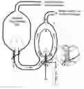
FIG. 1 Illustrates the carrier gas storage and heating system elements which deliver engine induction carrier gas to the heat converting mechanical work engine.
FIG. 2 shows a compact, high volume W9 piston type implementation of a RAKH Cycle Engine.
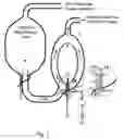
FIG. 3 illustrates the exhaust recovery system that returns dry carrier gas back to the carrier gas storage and heating system of FIG. 1.
FIGS. 4-6 show the thermodynamic sequence of Pressure, Temperature, and Volume at initial conditions, compression, and superheated liquid injection for a piston. FIG. 4 shows mass, and initial P, V, and T, at the beginning of compression. FIG. 5 shows P, V, and T, at TDC after maximum compression and; FIG. 6 at Top Dead Center (TDC) after liquid injection, at the start of the power stroke using the 4-stroke RAKH cycle engine described in FIGS. 1-3 and the set of initial conditions selected in the last computer printout listing, listing 6.
Listings 1-6 are computer program listings which show power and efficiency variations and the thermodynamic conditions of the RAKH Cycle Engine Run at uniform incremental points of the cycle under variations of compression ratio, initial carrier gas induction temperatures, and liquid injection quantities for water injected near the critical temperature at 704 degrees F.
| COMPUTER LISTINGS |
| Listing 1 is a computer printout for 8:1 compression at 1200 deg. F. starting gas temperature. |
| Argon @ STP = 39.948 grams for 22.4 liters |
| Cp = .133; Cv = .075165; gamma = 1.769441 |
| T2 = 7760.784 deg. F. & P2 = 2813.341 psia; Head Vol. = 62.5 cc; |
| CR = 8:1; free Ambient = 300 deg. F. |
| Argon Pres/Temp compensated mass in grams = 1.37449 |
| Thermal energy per power cycle to heat Argon = .2049907 BTUs |
| Assumed free feed Water heat = 268 BTUs per pound |
| Thermal energy per power cycle to heat Water = 7.598673E−02 BTUs |
| Mechanical work done to compress the Argon is −928.0307 ft-lbs |
| ************************* Event 2 ********************************** |
| At TDC, inject .06 grams of superheated Water at 704 deg. F. |
| % Mole mass Argon = 95.81733% % Mole mass H2O = 4.18267% |
| ******************************************************************** |
| Since the injected Water is superheated, some flashes to vapor; |
| Volume .06 grams of Saturated vapor at 2784.7 psia = .390925 cc |
| So, Argon is further compressed and now occupies only 62.10907 cc |
| The cylinder pressure however, decreases to 2784.7 psia |
| as a result of all the Water converting to saturated vapor |
| and the carrier gas temperature changes to 7638.407 |
| Equalizing temperatures, the vapor's temperature goes up to meet |
| Argon's decreasing temperature at 5692.219 deg. F. |
| 8:1 Compression of Argon starting @ 1200 deg. F. & 71 psia |
| Calculating partial volumes of .06 grains Water vapor & 1.37449 grams Argon |
| yields 4.551353 & 57.94865 cc respectively after equalizing temperatures. |
| Sums of the partial volumes must equal the cylinder volume of 62.5 at TDC. |
| Angle | Temp. F. | PSIA | Cyl Vol | Steam | Argon | |
| 90 | 5692.219 | 2983.976 | 62.5 | 4.5513 | SUP | 57.94865 |
| 80 | 5415.021 | 2657.699 | 66.60092 | 4.9205 | SUP | 61.68034 |
| 70 | 4747.316 | 1959.702 | 78.80437 | 5.9693 | SUP | 72.83501 |
| 60 | 3973.675 | 1307.761 | 98.53674 | 7.6205 | SUP | 90.91614 |
| 50 | 3265.964 | 851.2669 | 124.8817 | 9.8463 | SUP | 115.0354 |
| 40 | 2691.061 | 564.1493 | 156.6411 | 12.607 | SUP | 144.0338 |
| 30 | 2241.762 | 387.6474 | 192.4153 | 15.710 | SUP | 176.7049 |
| 20 | 1897.452 | 278.4525 | 230.6973 | 19.435 | SUP | 211.2621 |
| 10 | 1624.841 | 208.0506 | 269.9732 | 22.626 | SUP | 247.347 |
| 0 | 1416.888 | 163.8102 | 308.8161 | 28.522 | SUP | 280.2934 |
| −10 | 1254.789 | 132.4055 | 345.9635 | 32.056 | SUP | 313.9067 |
| −20 | 1131.672 | 110.5387 | 380.3672 | 33.588 | SUP | 346.7791 |
| −30 | 1035.548 | 93.85143 | 411.2137 | 31.029 | SUP | 380.1843 |
| −40 | 963.3055 | 82.05675 | 437.9155 | 25.810 | SUP | 412.1045 |
| −50 | 908.7077 | 74.63467 | 460.0805 | 22.649 | SUP | 437.4312 |
| −60 | 868.5814 | 69.51414 | 477.4703 | 20.515 | SUP | 456.955 |
| −70 | 841.2895 | 66.18478 | 489.955 | 19.153 | SUP | 470.801 |
| −80 | 827.2404 | 64.29819 | 497.4729 | 18.418 | SUP | 479.0547 |
| −90 | 820.8011 | 63.6814 | 499.9999 | 18.153 | SUP | 481.8467 |
Exhaust pressure of the binary mixture is 63.6814 psia at 820.8011 degrees F. |
||||||
Work done is 947.6757 ft-lbs; |
||||||
Estimated W-9 Horsepower @ 3600 RPM = 9.644 hp |
||||||
Estimated heat for Argon = 55.3475 BTU/sec and for liquid = 20.51642 BTU/sec |
||||||
Theoretical Efficiency = 8.983552% |
| COMPUTER LISTINGS |
| Listing 2 is a computer printout for 8:1 compression at 1400 deg. F. starting gas temperature. |
| Argon @ STP = 39.948 grams for 22.4 liters |
| Cp = .133; Cv = .075165; gamma = 1.769441 |
| T2 = 8751.396 deg. F. & P2 = 2813.341 psia; Head Vol. = 62.5 cc; CR = 8:1; |
| free Ambient = 300 deg. F. |
| Argon Pres/Temp compensated mass in grams = 1.22667 |
| Thermal energy per power cycle to heat Argon = .2235992 BTUs |
| Free feed Water heat = 268 BTUs per pound |
| Thermal energy per power cycle to heat Water = 7.598673E−02 BTUs |
| Mechanical work done to compress the Argon is −928.0307 ft-lbs |
| ************************* Event 2 ********************************** |
| At TDC, inject .06 grams of superheated Water at 704 deg. F. |
| % Mole mass Argon = 95.3368% % Mole mass H2O = 4.663202% |
| ******************************************************************** |
| Since the injected Water is superheated, some flashes to vapor; |
| Volume .06 grams of Saturated vapor at 2784.7 psia = .3909251 cc |
| So, Argon is further compressed and now occupies only 62.10907 cc |
| The cylinder pressure however, decreases to 2784.7 psia |
| as a result of all the Water converting to saturated vapor |
| and the carrier gas temperature changes to 8614.273 |
| Equalizing temperatures, the vapor's temperature goes up to meet |
| Argon's decreasing temperature at 6153.344 deg. F. |
| 8:1 Compression of Argon starting @ 1400 deg. F. & 71 psia |
| Calculating partial volumes of .06 grams Water vapor & 1.22667 grams Argon |
| yields 4.858467 & 57.64153 cc respectively after equalizing temperatures. |
| Sums of the partial volumes must equal the cylinder volume of 62.5 at TDC. |
| Crank Angle | Temp. F. | PSIA | Cyl Vol | Steam | Argon |
| 90 | 6153.344 | 2999.854 | 62.5 | 4.8584 | SUP | 57.64153 |
| 80 | 5862.012 | 2672.399 | 66.60092 | 5.2606 | SUP | 61.34026 |
| 70 | 5153.316 | 1971.232 | 78.80437 | 6.3964 | SUP | 72.40793 |
| 60 | 4326.985 | 1315.87 | 98.53674 | 8.1837 | SUP | 90.35295 |
| 50 | 3575.412 | 856.8443 | 124.8817 | 10.600 | SUP | 114.2809 |
| 40 | 2964.404 | 568.0646 | 156.6411 | 13.612 | SUP | 143.0291 |
| 30 | 2475.762 | 390.3107 | 192.4153 | 16.938 | SUP | 175.4763 |
| 20 | 2105.5 | 280.4383 | 230.6973 | 20.979 | SUP | 209.7177 |
| 10 | 1816.841 | 209.6149 | 269.9732 | 24.602 | SUP | 245.3707 |
| 0 | 1590.476 | 165.1332 | 308.8161 | 30.892 | SUP | 277.9238 |
| −10 | 1414.789 | 133.8045 | 345.9635 | 34.761 | SUP | 311.2022 |
| −20 | 1279.843 | 111.3988 | 380.3672 | 36.596 | SUP | 343.7709 |
| −30 | 1175.548 | 94.80654 | 411.2137 | 34.345 | SUP | 376.8687 |
| −40 | 1095.426 | 82.59328 | 437.9155 | 28.434 | SUP | 409.4808 |
| −50 | 1035.117 | 74.75674 | 460.0805 | 24.783 | SUP | 435.2975 |
| −60 | 992.4648 | 69.61333 | 477.4703 | 22.471 | SUP | 454.9989 |
| −70 | 962.9454 | 66.27042 | 489.955 | 20.988 | SUP | 468.9663 |
| −80 | 945.4143 | 64.37533 | 497.4729 | 20.152 | SUP | 477.3203 |
| −90 | 938.8011 | 63.75652 | 499.9999 | 19.869 | SUP | 480.1304 |
Exhaust pressure of the binary mixture is 63.75652 psia at 938.801 degrees F. |
||||||
Work done is 953.8967 ft-lbs; |
||||||
Estimated W-9 Horsepower @ 3600 RPM = 12.697 hp |
||||||
Estimated heat for Argon = 60.37178 BTU/sec and for liquid = 20.51642 BTU/sec |
||||||
Theoretical Efficiency = 11.09368% |
| COMPUTER LISTINGS |
| Listing 3 is a computer printout for 10:1 compression at 1200 deg. F. starting gas temperature. |
| Argon @ STP = 39.948 grams for 22.4 liters |
| Cp = .133 Cv = .075165 gamma= 1.769441 |
| T2 = 9300.61 deg. F. & P2 = 2764.002 psia; Head Vol. = 50 cc; CR = 10:1; |
| free Ambient = 300 deg. F. |
| Argon Pres/Temp compensated mass in grams = .9098739 |
| Thermal energy per power cycle to heat Argon = .1356981 BTUs |
| Free feed Water heat = 268 BTUs per pound |
| Thermal energy per power cycle to heat Water = 6.332228E-02 BTUs |
| Mechanical work done to compress the Argon is -758.6626 ft-lbs |
| ************************* Event 2 ********************************** |
| At TDC, inject .05 grams of superheated Water at 704 deg. F. |
| % Mole mass Argon = 94.79099% % Mole mass H2O = 5.209018% |
| ******************************************************************** |
| Since the injected Water is superheated, some flashes to vapor; |
| Volume .05 grams of Saturated vapor at 2732.787 psia = .3402922 cc |
| So, Argon is further compressed and now occupies only 49.65971 cc |
| The cylinder pressure however, decreases to 2732.787 psia |
| as a result of all the Water converting to saturated vapor |
| and the carrier gas temperature changes to 9141.189 |
| Equalizing temperatures, the vapor's temperature goes up to meet |
| Argon's decreasing temperature at 6281.403 deg. F. |
| 10:1 Compression of Argon starting @ 1200 deg. F. & 47 psia |
| Calculating partial volumes of .05 grams Water vapor & .9098739 grams Argon |
| yields 4.185383 & 45.81462 cc respectively after equalizing temperatures. |
| Sums of the partial volumes must equal the cylinder volume of 50 at TDC. |
| Angle | Temp. F. | PSIA | Cyl Vol | Steam | Argon | |
| 90 | 6281.403 | 2961.447 | 50 | 4.1853 | SUP | 45.8146 |
| 80 | 5912.367 | 2556.354 | 54.21809 | 4.6300 | SUP | 49.5880 |
| 70 | 5050.044 | 1754.167 | 66.77021 | 5.8883 | SUP | 60.8818 |
| 60 | 4106.926 | 1084.716 | 87.06635 | 7.8927 | SUP | 79.1735 |
| 50 | 3294.834 | 663.436 | 114.1641 | 10.626 | SUP | 103.5371 |
| 40 | 2663.506 | 419.4027 | 146.8309 | 13.996 | SUP | 132.8349 |
| 30 | 2186.437 | 278.9729 | 183.6271 | 18.161 | SUP | 165.4661 |
| 20 | 1825.887 | 195.0003 | 223.0029 | 22.377 | SUP | 200.6253 |
| 10 | 1545.998 | 144.5772 | 263.401 | 29.013 | SUP | 234.3875 |
| 0 | 1334.585 | 110.1319 | 303.3537 | 31.682 | SUP | 271.6711 |
| −10 | 1173.009 | 85.30632 | 341.5625 | 25.712 | SUP | 315.8498 |
| −20 | 1050.427 | 69.7062 | 376.9491 | 19.498 | SUP | 357.4505 |
| −30 | 956.1718 | 59.6932 | 408.6769 | 15.727 | SUP | 392.9495 |
| −40 | 884.814 | 52.40205 | 436.1416 | 13.106 | SUP | 423.0352 |
| −50 | 830.8615 | 47.46509 | 458.9399 | 11.402 | SUP | 447.5375 |
| −60 | 794.1226 | 44.09988 | 476.8266 | 10.295 | SUP | 466.5308 |
| −70 | 768.5775 | 41.89244 | 489.6679 | 9.5812 | SUP | 480.0866 |
| −80 | 753.5972 | 40.63806 | 497.4006 | 9.1804 | SUP | 488.2202 |
| −90 | 749.0366 | 40.22953 | 499.9999 | 9.0537 | SUP | 490.9461 |
Exhaust pressure of the binary mixture is 40.2295 psia at 749.0366 degrees F. |
||||||
Work done is 778.1189 ft-lbs, |
||||||
Estimated W-9 Horsepower @ 3600 RPM = 9.551 hp |
||||||
Estimated heat for Argon = 36.6385 BTU/sec and for liquid = 17.0970 BTU/sec |
||||||
Theoretical Efficiency = 12.5612% |
| COMPUTER LISTINGS |
| Listing 4 is a computer printout for 10:1 compression at 1400 deg. F. starting gas temperature. |
| Argon @ STP = 39.948 grams for 22.4 liters |
| Cp = .133; Cv = .075165; gamma= 1.769441 |
| T2 = 10476.78 deg. F. & P2 = 2764.002 psia; Head Vol. = 50 cc; CR = 10:1; |
| free Ambient = 300 deg. F. |
| Argon Pres/Temp compensated mass in grams = .8120207 |
| Thermal energy per power cycle to heat Argon = .1480163 BTUs |
| Free feed Water heat = 268 BTUs per pound |
| Thermal energy per power cycle to heat Water = 6.332228E−02 BTUs |
| Mechanical work done to compress the Argon is −758.6626 ft-lbs |
| ************************* Event 2 ********************************** |
| At TDC, inject .05 grams of superheated Water at 704 deg. F. |
| % Mole mass Argon = 94.19968% % Mole mass H2O = 5.800325% |
| ******************************************************************** |
| Since the injected Water is superheated, some flashes to vapor; |
| Volume .05 grams of Saturated vapor at 2732.787 psia = .3402922 cc |
| So, Argon is further compressed and now occupies only 49.65971 cc |
| The cylinder pressure however, decreases to 2732.787 psia |
| as a result of all the Water converting to saturated vapor |
| and the carrier gas temperature changes to 10298.16 |
| Equalizing temperatures, the vapor's temperature goes up to meet |
| Argon's decreasing temperature at 6727.823 deg. F. |
| 10:1 Compression of Argon starting @ 1400 deg. F. & 47 psia |
| Calculating partial volumes of .05 grams Water vapor & .8120207 grams Argon |
| yields 4.432171 & 45.56783 cc respectively after equalizing temperatures. |
| Sums of the partial volumes must equal the cylinder volume of 50 at TDC. |
| Angle | Temp. F. | PSIA | Cyl Vol | Steam | Argon | |
| 90 | 6727.823 | 2977.473 | 50 | 4.4321 | SUP | 45.5678 |
| 80 | 6338.564 | 2570.751 | 54.21809 | 4.9082 | SUP | 49.3098 |
| 70 | 5432.52 | 1764.889 | 66.77021 | 6.2589 | SUP | 60.5112 |
| 60 | 4438.989 | 1092.14 | 87.06635 | 8.4068 | SUP | 78.6595 |
| 50 | 3582.834 | 668.1401 | 114.1641 | 11.363 | SUP | 102.8006 |
| 40 | 2915.923 | 422.6461 | 146.8309 | 15.036 | SUP | 131.794 |
| 30 | 2400.371 | 281.1099 | 183.6271 | 19.452 | SUP | 164.1748 |
| 20 | 2020.208 | 196.4961 | 223.0029 | 23.954 | SUP | 199.0484 |
| 10 | 1719.998 | 145.9168 | 263.401 | 31.284 | SUP | 232.1168 |
| 0 | 1492.543 | 111.1008 | 303.3537 | 34.328 | SUP | 269.025 |
| −10 | 1317.009 | 85.7609 | 341.5625 | 28.119 | SUP | 313.4429 |
| −20 | 1182.627 | 69.81921 | 376.9491 | 21.228 | SUP | 355.7203 |
| −30 | 1080.743 | 59.76393 | 408.6769 | 17.135 | SUP | 391.5417 |
| −40 | 1002.673 | 52.79094 | 436.1416 | 14.416 | SUP | 421.7255 |
| −50 | 944.4111 | 47.52547 | 458.9399 | 12.440 | SUP | 446.4995 |
| −60 | 902.3192 | 44.14756 | 476.8266 | 11.216 | SUP | 465.6096 |
| −70 | 873.3138 | 41.93295 | 489.6679 | 10.429 | SUP | 479.238 |
| −80 | 857.5972 | 40.67531 | 497.4006 | 9.9988 | SUP | 487.4018 |
| −90 | 851.0366 | 40.26515 | 499.9999 | 9.8487 | SUP | 490.1512 |
Exhaust pressure of the binary mixture is 40.2651 psia at 851.0366 degrees F. |
||||||
Work done is 783.384 ft-lbs; |
||||||
Estimated W-9 Horsepower @ 3600 RPM = 12.1361 hp |
||||||
Estimated heat for Argon = 39.96441 BTU/sec and for liquid = 17.0970 BTU/sec |
||||||
Theoretical Efficiency = 15.03015% |
| COMPUTER LISTINGS |
| Listing 5 is a computer printout for 12:1 compression at 1200 deg. F. starting gas temperature. |
| Argon @ STP = 39.948 grams for 22.4 liters |
| Cp = .133 Cv = .075165 gamma= 1.769441 |
| T2 = 10770.53 deg. F. & P2 = 2760.743 psia; Head Vol. = 41.6667 cc; CR = 12:1; |
| free Ambient = 300 deg. F. |
| Argon Pres/Temp compensated mass in grams = .6582066 |
| Thermal energy per power cycle to heat Argon = 9.816456E−02 BTUs |
| Free feed Water heat = 268 BTUs per pound |
| Thermal energy per power cycle to heat Water = 4.432559E−02 BTUs |
| Mechanical work done to compress the Argon is −648.5344 ft-lbs |
| ************************* Event 2 ********************************** |
| At TDC, inject .035 grams of superheated Water at 704 deg. F. |
| % Mole mass Argon = 94.951% % Mole mass H2O = 5.048999% |
| ******************************************************************** |
| Since the injected Water is superheated, some flashes to vapor; |
| Volume .035 grams of Saturated vapor at 2734.399 psia = .2378876 cc |
| So, Argon is further compressed and now occupies only 41.42878 cc |
| The cylinder pressure however, decreases to 2734.399 psia |
| as a result of all the Water converting to saturated vapor |
| and the carrier gas temperature changes to 10615.93 |
| Equalizing temperatures, the vapor's temperature goes up to meet |
| Argon's decreasing temperature at 7199.492 deg. F. |
| 12:1 Compression of Argon starting @ 1200 deg. F. & 34 psia |
| Calculating partial volumes of .035 grams Water vapor & .6582066 grams Argon |
| yields 3.331799 & 38.33487 cc respectively after equalizing temperatures. |
| Sums of the partial volumes must equal the cylinder volume of 41.6667 at TDC. |
| Angle | Temp. F. | PSIA | Cyl Vol | Steam | Argon | |
| 90 | 7199.492 | 2954.399 | 41.66667 | 3.3317 | SUP | 38.33487 |
| 80 | 6693.274 | 2474.644 | 45.96288 | 3.7609 | SUP | 42.20195 |
| 70 | 5581.69 | 1590.765 | 58.74744 | 4.9866 | SUP | 53.76077 |
| 60 | 4434.087 | 923.742 | 79.41944 | 6.9565 | SUP | 72.46288 |
| 50 | 3495.073 | 539.0018 | 107.019 | 9.6969 | SUP | 97.32202 |
| 40 | 2790.533 | 329.7793 | 140.2907 | 13.082 | SUP | 127.2083 |
| 30 | 2267.495 | 214.0209 | 177.7684 | 16.943 | SUP | 160.8246 |
| 20 | 1881.981 | 148.6708 | 217.8733 | 23.112 | SUP | 194.7608 |
| 10 | 1588.337 | 106.9171 | 259.0196 | 25.766 | SUP | 233.2534 |
| 0 | 1365.485 | 78.10737 | 299.7121 | 18.435 | SUP | 281.2764 |
| −10 | 1198.119 | 61.58424 | 338.6284 | 13.282 | SUP | 325.3464 |
| −20 | 1069.991 | 50.85831 | 374.6704 | 10.164 | SUP | 364.5055 |
| −30 | 972.6651 | 43.53189 | 406.9858 | 8.1669 | SUP | 398.8188 |
| −40 | 899.26 | 38.05911 | 434.9591 | 6.7535 | SUP | 428.2055 |
| −50 | 843.4289 | 34.49232 | 458.1796 | 5.8702 | SUP | 452.3094 |
| −60 | 805.2305 | 32.01327 | 476.3975 | 5.2878 | SUP | 471.1096 |
| −70 | 778.4795 | 30.39824 | 489.4766 | 4.9135 | SUP | 484.5631 |
| −80 | 764.2328 | 29.48538 | 497.3525 | 4.7102 | SUP | 492.6423 |
| −90 | 758.4092 | 29.18753 | 499.9999 | 4.6399 | SUP | 495.36 |
Exhaust pressure of the binary mixture is 29.1875 psia at 758.4092 degrees F. |
||||||
Work done is 666.9431 ft-lbs; |
||||||
Estimated W-9 Horsepower @ 3600 RPM = 9.0370 hp |
||||||
Estimated heat for Argon = 26.50443 BTU/sec |
||||||
Estimated heat for injected liquid = 11.96791 BTU/sec |
||||||
Theoretical Efficiency = 16.59994% |
| COMPUTER LISTINGS |
| Listing 6 is a computer printout for 12:1 compression at 1400 deg. F. starting gas temperature. |
| Argon @ STP = 39.948 grams for 22.4 liters |
| Cp = .133 Cv = .075165 gamma= 1.769441 |
| T2 = 12123.84 deg. F. & P2 = 2760.743 psia; Head Vol. = 41.6667 cc; CR = 12:1; |
| free Ambient = 300 deg. F. |
| Argon Pres/Temp compensated mass in grams = .5874192 |
| Thermal energy per power cycle to heat Argon = .1070757 BTUs |
| Free feed Water heat = 268 BTUs per pound |
| Thermal energy per power cycle to heat Water = 4.432559E−02 BTUs |
| Mechanical work done to compress the Argon is −648.5344 ft-lbs |
| ************************* Event 2 ********************************** |
| At TDC, inject .035 grams of superheated Water at 704 deg. F. |
| % Mole mass Argon = 94.37678% % Mole mass H2O = 5.62322% |
| ******************************************************************** |
| Since the injected Water is superheated, some flashes to vapor; |
| Volume .035 grams of Saturated vapor at 2734.399 psia = .2378876 cc |
| So, Argon is further compressed and now occupies only 41.42878 cc |
| The cylinder pressure however, decreases to 2734.399 psia |
| as a result of all the Water converting to saturated vapor |
| and the carrier gas temperature changes to 11950.6 |
| Equalizing temperatures, the vapor's temperature goes up to meet |
| Argon's decreasing temperature at 7714.418 deg. F. |
| 12:1 Compression of Argon starting @ 1400 deg. F. & 34 psia |
| Calculating partial volumes of .035 grams Water vapor & .5874192 grams Argon |
| yields 3.532375 & 38.13429 cc respectively after equalizing temperatures. |
| Sums of the partial volumes must equal the cylinder volume of 41.6667 at TDC. |
| Angle | Temp. F. | PSIA | Cyl Vol | Steam | Argon | |
| 90 | 7714.418 | 2969.924 | 41.66667 | 3.5323 | SUP | 38.1342 |
| 80 | 7173.274 | 2488.044 | 45.96288 | 3.9886 | SUP | 41.9742 |
| 70 | 6005.69 | 1600.18 | 58.74744 | 5.3040 | SUP | 53.4433 |
| 60 | 4794.087 | 929.7141 | 79.41944 | 7.4253 | SUP | 71.9941 |
| 50 | 3802.525 | 542.8007 | 107.019 | 10.385 | SUP | 96.6333 |
| 40 | 3053.34 | 332.2596 | 140.2907 | 14.051 | SUP | 126.2389 |
| 30 | 2489.76 | 215.678 | 177.7684 | 18.227 | SUP | 159.541 |
| 20 | 2079.981 | 149.9546 | 217.8733 | 24.869 | SUP | 193.0038 |
| 10 | 1766.371 | 107.7979 | 259.0196 | 27.897 | SUP | 231.1217 |
| 0 | 1527.485 | 78.36844 | 299.7121 | 20.123 | SUP | 279.5889 |
| −10 | 1344.46 | 61.65889 | 338.6284 | 14.465 | SUP | 324.1626 |
| −20 | 1205.932 | 50.90034 | 374.6704 | 11.079 | SUP | 363.5905 |
| −30 | 1098.773 | 43.55795 | 406.9858 | 8.8979 | SUP | 398.0878 |
| −40 | 1019.412 | 38.42031 | 434.9591 | 7.4608 | SUP | 427.4982 |
| −50 | 959.3326 | 34.51474 | 458.1796 | 6.4075 | SUP | 451.7721 |
| −60 | 915.2305 | 32.03089 | 476.3975 | 5.7622 | SUP | 470.6352 |
| −70 | 886.4795 | 30.41343 | 489.4766 | 5.3566 | SUP | 484.12 |
| −80 | 868.9189 | 29.49901 | 497.3525 | 5.1273 | SUP | 492.2252 |
| −90 | 864.4092 | 29.20099 | 499.9999 | 5.0581 | SUP | 494.9417 |
Exhaust pressure of the binary mixture is 29.2010 psia at 864.4092 degrees F. |
||||||
Work done is 671.0901 ft-lbs, |
||||||
Estimated W-9 Horsepower @ 3600 RPM = 11.073 hp |
||||||
Estimated heat for Argon = 28.9104 BTU/sec and for liquid = 11.9679 BTU/sec |
||||||
Theoretical Efficiency = 19.14237% |
The RAKH Cycle Engine utilizes a novel thermodynamic cycle, which is described here in detail. FIG. 1 shows an insulated storage tank (1) that is initially full of the selected carrier gas. Argon is used as the preferred carrier gas because of its calculation friendly nature of maintaining a nearly constant specific heat. The carrier gas is nearly free of any liquid water when it exits the storage tank because of the ceramic fuel filter (8), which passes gas through it but not water, similar to a common ceramic gasoline fuel filter that allows gasoline to pass through but not water. The carrier gas will pass through the ceramic with negligible back pressure. Excess water can be drained from the storage tank through manual operated valve (9) and may be collected or discarded on exiting through the drain tube after the valve. The carrier gas is drawn though the heater (3) by the intake stroke of the RAKH Engine (see FIG. 2). The heater is warmed by the boron burner (4), which is continuously fed oxygen from tank (6) through the thermostatically controlled regulator valve (7), controlled by thermostat (5). Thermostat (5) is also contains a high voltage spark plug, which sparks during startup only. There is no exit from the burner except through orifices in the boron feeder assembly (11), which plugs the exit automatically with slow draining boria (the glassy solid product of the combustion of boron in oxygen). The close-up particulars of the boron feeder assembly are shown the adjacent drawing detail, which shows the oxygen orifice entering at the right side below and exiting through a little tungsten tube (14), which is bent toward the boron filament at its upper end. This tungsten tube serves to help blow away the glassy boria protective coating formed on the surface of the boron. The intense heat at the tip would melt most other metal tubes that could be used but tungsten is the least likely to melt in this application. A plug of boria should be left in the upper end of the boron feeder assembly. Electrical heating coils (13) will help warm this boria plug which will begin to drain out the boria drain tube (12). Boria (15) flowing out slowly is the only thing that impedes the oxygen. Otherwise, oxygen would exit through the same tube (12). The boria also seals the boron filament entering the burner. The boron feeder assembly (11) boron entry hole diameter must be slightly larger than the largest diameter of the solid boron filament being forced into the boron feeder assembly. There will be virtually no possibility for extrusion since boron is nearly as hard as diamond. FIG. 1 is presented only to show a viable hot gas delivery system, which produces none of the so called greenhouse waste gasses of current carbon fuel based engines. Boron burns to form the solid waste boria and has no exhaust gas!
FIG. 2. shows a compact diesel type engine converted to a RAKH Cycle Engine. The RAKH Cycle Engine intakes a hot carrier gas rather than air through intake port (C) via intake valve (I). Like in a diesel, the carrier gas is then compressed adiabatically, requiring work input from a typical diesel Crankshaft Flywheel (not shown on FIG. 2). At a point very near Top Dead Center for the piston, FIG. 4 shows the thermodynamic results of injecting superheated water (water heated to a point above the saturation temperature with respect to its pressure environment after being injected into the cylinder). FIG. 4 uses the conditions assumed in the listing of FIG. 6. Water stored in pressure vessel (M) flows through high pressure delivery line (L) into injection channel (K) surrounding the inlet of electronically heated and electronically controlled plunger (B) of injector (D) which is like a diesel injector but it injects a superheated liquid, namely water in these illustrated Figures. The water cannot burn, of course, but conditions are so hot in the cylinder that it seems to explode into steam from its own excess enthalpy at the pressure of its new environment within the cylinder and a rapid heating from the adiabatically heated carrier gas. The mixture of steam and the carrier gas have more pressure than the carrier gas did alone, which cause net work output from piston (P) down connecting rod (F) forcing crankshaft connected at crank offset throw (J) to exert a rotational torque on crankshaft (G) with more average force due to pressure increased during the power stroke than that required to compress the carrier gas. Like other 4 stroke engines, the power stroke is followed by the exhaust stroke, which forces the exhaust mixture out through valve (E) and on out Exhaust port (A) to the condenser/dryer system illustrated in FIG. 3.
FIG. 3 Illustrates the Condenser System, which saves the carrier gas and removes the small volume of vapor in the mixture caused by injecting the superheated liquid. Steam in the preferred implementation presented here. Wet mixture (W) enters the Condenser tank (T) where it is immediately cooled by the spray injection (I) that is pumped into the condenser by continuous centrifugal pump (R), which pumps water from the condenser through water cooled radiator (G). Cooling water (C) comes from virtually any large source of cooling water. Engine induction continually pulls carrier gas (V) out of the condenser through two ceramic disks with high pressure water trapped between those two ceramic disks (similar to the ceramic filter described in FIG. 1). Any water vapor trying to leave the condenser with carrier gas (V) is cooled and trapped in the water between the two ceramic disks. The trapped water is continuously heated by the addition of steam and its volume continuously increases until pressure relief valve (P) releases water back into the condenser hydraulic gear pump (M) continuously pumps water from pressurized hot water tank (B) through water cooled radiator (H) or through bypass line (U) depending on the temperature controlled thermostatic valves (K) and (L). Valve (K) opens when the temperature increases and valve (L) remains open when the temperature is low. The valves are both open at a selectable preset equilibrium temperature so both valves are never closed at the same time. After exiting the throat of the condenser past the pressure relief valve (P), a sleeved (S) U-tube routes the flow back into the throat of the condenser between the two ceramic disks (D) back into tank (B) and into the base of collector dish (Q), which is normally submerged. Another ceramic disk (D) blocks the exit of water via the throat at the upper end of pressurized tank (B). Valve J is a pressure relief valve set to release at a pressure that is only half of the pressure setpoint that opens pressure relief valve (P). If any carrier gas gets transported into tank (B) then it should eventually be released with a small amount of steam back into the condenser. A little steam in the dried carrier gas shouldn't affect operation of the RAKH Cycle Engine. The drawing shows release into the dry gas side rather than back into the condenser to simplify drawing the vent line.
Eventually the liquid at the bottom of the condenser would overflow so a float controller (F) sends a signal to open drain line valve (E) draining to a low pressure air vented overflow tank, not shown on the drawing. Steam trapped between the ceramic disks continually heats tank (B) and preheats the carrier gas a little bit after the spray injection (I) has cooled it for a slight added efficiency bonus in capturing and recycling the carrier gas with a closed cycle.
FIG. 4 shows the theoretical thermodynamic conditions of Pressure, Volume, and Temperature for a single cylinder after the induction stroke at Bottom Dead Center (BDC) for 1 piston given the particular RAKH Cycle Engine configuration and initial conditions selected for computer listing number 6, which follows.
FIG. 5 shows the theoretical thermodynamic conditions of Pressure, Volume, and Temperature after the compression stroke at Top Dead Center (TDC) from the initial state in FIG. 4.
FIG. 6 shows the same piston position at TDC as in FIG. 5 an instant later after the water is injected, showing the final P, V, and T for the mixture.
Listings 1 and 2 computer printouts are for an 8 to 1 compression ratio RAKH Cycle Engine with 0.06 grams of water injected at 704 degrees F.
Listings 3 and 4 computer printouts are for a 10 to 1 compression ratio RAKH Cycle Engine with 0.05 grams of water injected at 704 degrees F.
Listings 5 and 6 computer printouts are for a 12 to 1 compression ratio RAKH Cycle Engine with 0.035 grams of water injected at 704 degrees F.
Listing 1 has 1200 degree F. initial Argon carrier gas temperature and 71 psia intake pressure.
Listing 2 has 1400 degree F. initial Argon carrier gas temperature and 71 psia intake pressure.
Listing 3 has 1200 degree F. initial Argon carrier gas temperature and 47 psia intake pressure.
Listing 4 has 1400 degree F. initial Argon carrier gas temperature and 47 psia intake pressure.
Listing 5 has 1200 degree F. initial Argon carrier gas temperature and 34 psia intake pressure.
Listing 6 has 1400 degree F. initial Argon carrier gas temperature and 34 psia intake pressure.
At TDC for each of these listings, the maximum pressure is close to 3000 psia
Claims
1. A thermodynamic engine using a heated carrier gas, compressed adiabatically to further increase temperature and induce rapid heat transfer into a nearly boiling liquid injected into the lower pressure, hot carrier gas, forcing vaporization due to a combination of the heat received from the high temperature carrier gas and its own excess enthalpy over its saturation enthalpy after injection into the lower than saturation pressure environment of the compressed carrier gas, yielding an overall pressure increase from the combined partial pressures at the point of maximum compression, which will then generate an excess of mechanical work via expansion over the work expended to compress the gas.
2. An engine using a gas or combination of gasses, unburned, and compressed adiabatically to increase temperature for the purpose of accelerating transfer of additional heat to a previously heated injected liquid, or other substance above its critical temperature and pressure, which when injected to form a mixture, thereby produces a sum of partial pressures, without combustion after the induction of the carrier gas, greater than the carrier gas pressure at its most compressed volume, which produces a net work output.
3. A thermodynamic refrigeration cycle, which uses any said real carrier gas in an adiabatic compression to concentrate thermal energy during the compression event to increase the temperature of the carrier gas and achieves rapid cooling upon injection of a liquid substance that takes up part of the heat of the carrier gas.
4. An engine having any arbitrary selection of a first cycle event selected from the present RAKH Cycle with the remaining events in the same relative cyclical sequence described in the present invention, where the essence the cycle relies on a transfer of concentrated thermal energy in the form of increased temperature due to compression of a carrier gas and subsequent transfer of a portion of that thermal energy to an injected substance without resort to internal combustion, which increases overall mixture pressure after equalization of their temperatures to produce a net positive work output.
5. An engine, independent of the number of strokes required to implement the thermodynamic cycle, not excluding a turbine or any other mechanical compression type engine, which implements the said thermodynamic cycle in the sequence specified or continuously at various locations in the engine simultaneously, as in a turbine.
Images & Drawings included:


Sources:
- United States Patent and Trademark Office - verify current appl. status at the USPTO↗
Similar patent applications:
Recent applications in this class:
- » 20220082048 2022-03-17
Camshaft for internal-combustion engine - » 20210164389 2021-06-03
Method for operating an internal combustion engine - » 20210054780 2021-02-25
Internal-combustion engine and drive system - » 20180038275 2018-02-08
Six-stroke and eight-stroke internal combustion engines - » 20160032821 2016-02-04
Six Stroke Internal-Combustion Engine - » 20150136083 2015-05-21
Inverted V-8 I-C engine and method of operating same in a vehicle - » 20140366819 2014-12-18
Six-stroke cycle engine having scavenging stroke - » 20140326202 2014-11-06
Six Stroke Internal Combustion Engine and a Method of Operation - » 20140224195 2014-08-14
Six-stroke engine - » 20140158085 2014-06-12
Six-Stroke Combustion Cycle Engine and Process