Flat cable arrangement for a scanner
US20050173535A1
2005-08-11
11/043,498
2005-01-26
✅ Patent granted
US 7,040,537 B2
2006-05-09
-
-
Uyen-Chau N. Le
2025-01-26
Abstract:
A scanner. The scanner comprises a flat cable and a cable holder. The flat cable comprises a first end and a second end. The second end moves to or away from the first end along a first path. The cable holder is disposed at a restricting point between the first end and the second end, whereby, when the second end moves to the first end, the cable holder contains and folds the flat cable.
Assignee:
- BENQ CORPORATION 442 🇹🇼 TAOYUAN, Taiwan
Interested in similar patents?
Get notified when new applications in this technology area are published.
Classification:
G06K7/00 IPC
Methods or arrangements for sensing record carriers, e.g. for reading patterns
H04N1/0083 » CPC main
Scanning, transmission or reproduction of documents or the like, e.g. facsimile transmission; Details thereof Arrangements for transferring signals between different components of the apparatus, e.g. arrangements of signal lines or cables
H04N1/1013 » CPC further
Scanning, transmission or reproduction of documents or the like, e.g. facsimile transmission; Details thereof; Scanning arrangements, i.e. arrangements for the displacement of active reading or reproducing elements relative to the original or reproducing medium, or using flat picture-bearing surfaces with sub-scanning by translatory movement of at least a part of the main-scanning components
Description
BACKGROUND OF THE PRESENT INVENTION1. Field of the Present Invention
The present invention relates to a scanner and in particular to a scanner with increased element clearance.
2. Description of the Related Art
FIG. 1a shows a conventional scanner 10, in which a flat cable 12 is disposed in the center of a housing 13. When scanner module 11 moves, flat cable 12 is stretched or bent with movement thereof. When flat cable 12 is bent, it can contact and possibly damage a transparent plate (not shown) above scanner module 11.
FIG. 1b shows another conventional scanner 20, in which a flat cable 22 is disposed on a structure 24 of the housing 23. When scanner module 21 moves, flat cable 22 is stretched or bent, and, when bent, may lodge between scanner module 21 and housing 23, restricting motion of scanner module 21.
SUMMARY OF THE PRESENT INVENTIONThe scanner of the present invention comprises a flat cable, a shaft, a scan module and a cable holder. The shaft is disposed in the scanner. The scan module is movably disposed on the shaft. The flat cable has a first end, and a second end connected to the scan module. The cable holder is disposed at a restricting point between the first end and the second end. The cable holder has an opening, moving on the shaft with the opening.
The present invention prevents the flat cable from contacting the transparent plate or restricting movement of the scan module, thereby reducing scan errors and increasing lifetime of the scanner.
BRIEF DESCRIPTION OF THE DRAWINGSThe present invention can be more fully understood by reading the subsequent detailed description and examples with references made to the accompanying drawings, wherein:
FIG. 1a shows a conventional scanner;
FIG. 1b shows another conventional scanner;
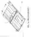
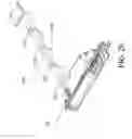
FIG. 2a is an exploded view of the main elements of the present invention;
FIG. 2b is a combined view of the main elements of the present invention;
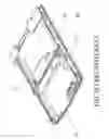
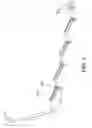
FIG. 3 shows a detailed structure of the flat cable;
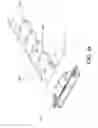
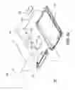
FIG. 4a is an exploded view of the present invention;
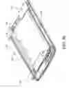
FIG. 4b is a combined view of the present invention.
DETAILED DESCRIPTION OF THE PRESENT INVENTIONAs shown in FIG. 2a, the scanner of the present invention comprises a flat cable 120, a shaft 130, a scan module 110 and cable holders 125. The shaft 130 is disposed in the scanner. The scan module 110 is movably disposed on the shaft 130. The flat cable 120 has a first end 121 and a second end 122. The second end 122 is connected to the scan module 110 by a connector 123. The cable holders 125 are disposed of restricting points between the first end 121 and the second end 122. Each cable holder 125 has an opening 126, moving on the shaft 130 with the opening 126. FIG. 2 is a combined figure of the flat cable 120, the shaft 130, the scan module 110 and the cable holders 125.
The flat cable 120 is pleated in, for example, a triangular or sine wave profile, and comprises extendable and compressible metal lines, collapsing into pleats by folding. As shown in FIG. 3, cable holders 125 are attached on the flat cable 120 by attachment portions 127. Cable holders 125 can also be directly formed on the flat cable 120, of non-abrasive plastic material which is light and highly flexible.
Back to FIG. 2b, when the scan module 110 moves along the shaft 130 (first path), the second end of the flat cable 120 is moved away from the first end, the cable holders 125 move along the shaft 130, such that distance between the cable holders 125 increases, and the flat cable 120 is extended. When the scan module 110 returns along the shaft 130, the second end 122 of the flat cable 120 approaches the first end 121, the cable holders 125 move along the shaft 130, and the distance therebetween decreases, and the flat cable 120 collapses. The cable holders 125 control bending angle of the flat cable 120 to maintain a constant distance between the restricting points and the first path; thus, the cable holders 125 prevent the flat cable 120 from contacting a transparent plate (not shown) above the scanner module 110 or lodging between the scanner module 110 and the housing (not shown).
In the embodiment mentioned above, the cable holders 125 and the first and the second ends of the flat cable 120 move along the shaft 130 (first path). However, the cable holders 125 can also move along a second path (not shown) parallel to the first path.
Additionally, if the flat cable 120 comprises elastic metal lines, the cable holders 125 can be eliminated, with the flat cable 120 collapsing by elasticity.
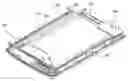
As shown in FIG. 4a, the flat cable 120 is connected to a circuit board 160 by conductive line 124. The circuit board 160 controls the movement of the scan module 110. The flat cable 120, the shaft 130, the scan module 110, the cable holders 125 and the circuit board 160 are disposed in the housing 150. A transparent plate 140 is disposed on the housing 150. FIG. 4b is a combination figure of the elements mentioned. The shaft 130 is disposed in a side portion of the housing 150.
The present invention prevents the flat cable from rubbing the transparent plate and restricting movement of the scan module, thereby reducing scan errors and increasing lifetime of the scanner.
While the present invention has been described by way of example and in terms of the preferred embodiments, it is to be understood that the present invention is not limited to the disclosed embodiments. To the contrary, it is intended to cover various modifications and similar arrangements (as would be apparent to those skilled in the art) . Therefore, the scope of the appended claims should be accorded the broadest interpretation so as to encompass all such modifications and similar arrangements.
Claims
1. A scanner, comprising:
a flat cable, comprising a first end and a second end, the second end moving to or away from the first end along a first path; and
a cable holder, disposed at a restricting point between the first end and the second end, whereby, when the second end moves to the first end, the cable holder contains and folds the flat cable.
2. The scanner as claimed in claim 1, wherein the flat cable has pleats.
3. The scanner as claimed in claim 2, wherein the flat cable pleats are triangular.
4. The scanner as claimed in claim 2, wherein the flat cable pleats follow a sine wave profile.
5. The scanner as claimed in claim 2, wherein the cable holder moves along a second path and contains the flat cable to keep a constant distance between the restricting point and the first path when the second end is moved along the first path.
6. The scanner as claimed in claim 5, wherein the first path is parallel to the second path.
7. The scanner as claimed in claim 1, wherein the cable holder is fixed on the restricting point.
8. The scanner as claimed in claim 1, further comprising:
a housing;
a shaft, disposed in the housing on the first path;
and
a scan module, movably disposed on the shaft and connected to the second end of the flat cable.
9. The scanner as claimed in claim 8, wherein the scan module is oriented lengthwise and comprises an end portion on the shaft.
10. The scanner as claimed in claim 9, wherein the cable holder comprises an opening through which the shaft passes, and the cable holder slides along the shaft with the opening.
11. The scanner as claimed in claim 1, wherein the cable holder comprises non-abrasive material.
12. The scanner as claimed in claim 1, wherein the cable holder comprises plastic.
Images & Drawings included:
Sources:
- United States Patent and Trademark Office - verify current appl. status at the USPTO↗
Recent applications in this class:
- » 20250267225 2025-08-21
Methods and Systems for Communicating Data on an Electronic Device - » 20240106951 2024-03-28
Image forming apparatus having a cable and a reinforcing member along the cable - » 20220279078 2022-09-01
Image forming apparatus having a cable protected by a reinforcing member - » 20220038583 2022-02-03
Image reading apparatus and image forming apparatus - » 20210409552 2021-12-30
Original reading apparatus - » 20210281687 2021-09-09
Multifunction peripheral capable of executing image processings in parallel, method of controlling same, and storage medium - » 20210014361 2021-01-14
Image reading apparatus and image forming apparatus - » 20200344363 2020-10-29
Information processing system - » 20200322488 2020-10-08
Original reading apparatus - » 20200236226 2020-07-23
Image reading apparatus
Recent applications for this Assignee:
- » 20090231371 2009-09-17
APPARATUS AND METHOD FOR SUPPLYING VOLTAGE TO NOZZLE IN INKJET PRINTER - » 20080310295 2008-12-18
METHODS FOR EXTRA APPENDING DATA IN A MULTIPLE LAYER DISC - » 20080239254 2008-10-02
Projector with enhanced grounding effect - » 20080150961 2008-06-26
DISPLAYS WITH EMBEDDED COLOR TRACKING ALGORITHM BASED ON PANEL OPTICAL CHARACTERISTICS - » 20080142664 2008-06-19
SUPPORTS FOR ELECTRONIC DEVICES - » 20080132258 2008-06-05
METHOD AND APPARATUS FOR BARRING SHORT MESSAGES - » 20080113546 2008-05-15
Portable electronic device - » 20080106529 2008-05-08
PROCESSING METHODS AND SYSTEMS FOR DRIVERS - » 20080104598 2008-05-01
SYSTEMS AND METHODS FOR OPERATION SCHEDULING - » 20080098381 2008-04-24
SYSTEMS AND METHODS FOR FIRMWARE UPDATE IN A DATA PROCESSING DEVICE