Wrench with display device
US20050178248A1
2005-08-18
10/779,675
2004-02-18
✅ Patent granted
US 7,013,763 B2
2006-03-21
-
-
Lee D. Wilson | Alvin J Grant
2024-06-26
Abstract:
A display device is connected to a head of a wrench including a fixed jaw and a movable jaw. A variable electric resistor is connected to a side of the head and electrically connected to the display device. The movable jaw has a contact member which is movably in contact with the variable electric resistor. The changes of the value of electric resistance of the variable electric resistor is transformed into digitals to show the distance between the fixed jaw and the movable jaw, that is, the size of an object clamped between the fixed jaw and the movable jaw.
Interested in similar patents?
Get notified when new applications in this technology area are published.
Classification:
G01B3/38 » CPC main
Instruments as specified in the subgroups and characterised by the use of mechanical measuring means Gauges with an open yoke and opposed faces, i.e. calipers, in which the internal distance between the faces is fixed, although it may be preadjustable
B25B13/12 » CPC further
Spanners; Wrenches with adjustable jaws the jaws being slidable
B25B13/14 » CPC further
Spanners; Wrenches with adjustable jaws the jaws being slidable by rack and pinion, worm or gear
B25B13/16 IPC
Spanners; Wrenches with adjustable jaws the jaws being slidable by screw or nut
Description
FIELD OF THE INVENTIONThe present invention relates to a wrench having a movable jaw and a fixed jaw. A display device is connected to the wrench and displays the size of the object to be clamped.
BACKGROUND OF THE INVENTIONA conventional adjustable wrench generally includes a handle with a fixed jaw integrally connected to an end thereof and a movable jaw which is movable relative to the fixed jaw so as to clamp an object by the fixed jaw and the movable jaw. Generally, the size of the object clamped by the wrench cannot be told, the user has to use another measurement tool to measure the object before it is rotated by the wrench. A wrench that is developed to have scale marks pressed in a side of the wrench so that the user may check the marks to know the size of the object. Nevertheless, it requires a certain experience to tell the correct of the scale marks. In other words, there is a potential error could happened when reading the scale marks if the user views the scale marks at an angle. Besides, the scales are pressed in the surface of the wrench and will be worn out after the wrench is used for a period of time.
The present invention intends to provide a wrench that has a display device which transfers changes of resistance of a variable electric resistor when clamping the object to display the correct size in the screen of the display device.
SUMMARY OF THE INVENTIONThe present invention relates to wrench which comprises a fixed jaw integrally connected to an end of the handle and a movable jaw which is movable in a slot defined in the head of the wrench. A through hole is defined through the head and a thumb screw is rotatably engaged with the through hole. The thumb screw is engaged with a rack portion of the movable jaw so that the movable jaw is movable toward the fixed jaw by rotating the thumb screw. A display device is connected to a side of the head of the wrench and includes a screen. A variable electric resistor is connected to the head and electrically connected to the display device. The movable jaw has a contact member which is movably in contact with the variable electric resistor. By the change of the value of the electric resistance, the display device displays the sizes between the fixed jaw and the movable jaw.
The present invention will become more obvious from the following description when taken in connection with the accompanying drawings which show, for purposes of illustration only, a preferred embodiment in accordance with the present invention.
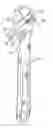
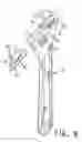
BRIEF DESCRIPTION OF THE DRAWINGSFIG. 1 is a perspective view to show the first embodiment of the wrench of the present invention;
FIG. 2 is an end cross sectional view to show that the contact member on the movable jaw is in contact with the variable electric resistor;
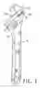
FIG. 3 is a side view of the first embodiment of the wrench of the present invention;
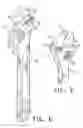
FIG. 4 is a side view to show that an object is clamped between the fixed jaw and the movable jaw of the first embodiment of the wrench of the present invention;
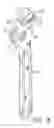
FIG. 5 shows a second embodiment of the present invention wherein two display devices are connected on two sides of the wrench of the present invention;
FIG. 6 shows one side of the wrench of the second embodiment of the present invention;
FIG. 7 shows the other side of the wrench of the second embodiment of the present invention;
FIG. 8 shows a third embodiment of the wrench of the present invention, and
FIG. 9 is an exploded view to show a fourth embodiment of the wrench of the present invention.
DETAILED DESCRIPTION OF THE PREFERRED EMBODIMENTSReferring to FIGS. 1 to 3, the wrench 10 of the present invention comprises a handle and a head, a fixed jaw 11 integrally connected to an end of the handle. A through hole is defined through the head and a thumb screw 13 is rotatably engaged with the through hole. A slot 12 is defined in an end of the end of the head.
A movable jaw 30 has an insertion 31 which is movably engaged with the slot 12 and a rack portion 32 is defined in the insertion of the movable jaw 30 and engaged with the thumb screw 13 so that the movable jaw 30 is movable toward the fixed jaw 11 and along the slot 12 by rotating the thumb screw 13.
A display device 21 is connected to a side of the head of the wrench and includes a screen 211 and an adjustment button 212 which is used to adjust the molds displayed in the screen 211. A variable electric resistor 20 is connected to the head and electrically connected to the display device 21. The movable jaw 30 has a contact member 22 which is movably in contact with the variable electric resistor 20.
Referring to FIG. 4, when clamping an object such as a nut 40 by the wrench, the user (not shown) rotates the thumb screw 13 to move the movable jaw 30 toward the fixed jaw 11 till the nut 40 is clamped between the fixed jaw 11 and the movable jaw 30. During movement of the movable jaw 30, the contact member 22 is slid on the variable electric resistor 20 and the value of the resistance is changed. The display device 21 transfers the change of the resistance into digits to show the size of the nut 40. The user can see the digits displayed in the screen 211 and acknowledges the size of the nut 40 immediately.
FIGS. 5 to 7 show that two display devices 21 are respectively connected to two opposite sides of the head of the wrench. The two display devices 21 provide more convenience to the user to check the information of the object that is clamped by the wrench.
FIG. 8 shows that the display device 21 including a screen 211 and an adjustment button 212 further has a light-activation electric resistor 50 connected to one of two insides of the slot 12 and a light source 52 connected to the other inside of the slot 12. The light-activation electric resistor 50 is electrically connected to the display device 21 and the light source 52 emits a light beam toward the light-activation electric resistor 50. The movable jaw 30 moves along the slot 12 to clamp an object which is not shown and blocks the light beam emitted from the light source 52. The movement of the movable jaw 30 blocks a part of the path of the light beam depending the size of the object. The change of the light beam that is received by the light-activation electric resistor 50 is transferred into digits displayed in the screen 211.
FIG. 9 shows yet another embodiment wherein the display device 21 includes a screen 211 and an adjustment button 212. A light source 61 is connected to one of the insides of the slot 12 and a photoelectric member 60 is connected to the other inside of the slot 12 so as to receive a light beam emitted from the light source 61. A fringe 62 is connected to the insertion 31 of the movable jaw 30 such that when clamping an object between the fixed jaw 11 and the movable jaw 30, the light beam emitted from the light source 61 is partially blocked by the fringe 62 so that the light beam to be received by the photoelectric member 60 is changed when different size of objects are clamped. The change of the light beam received by the photoelectric member 60 is transferred into digits displayed in the screen 211.
While we have shown and described the embodiment in accordance with the present invention, it should be clear to those skilled in the art that further embodiments may be made without departing from the scope of the present invention.
Claims
1. A wrench comprising:
a handle and a head, a fixed jaw integrally connected to an end of the handle, a through hole defined through the head and a thumb screw rotatably engaged with the through hole, a slot defined in an end of the end of the head;
a movable jaw having an insertion which is movably engaged with the slot, a rack portion defined in the insertion of the movable jaw and engaged with the thumb screw so that the movable jaw is movable toward the fixed jaw by rotating the thumb screw, and
a display device connected to a side of the head of the wrench and including a screen, a variable electric resistor connected to the head and electrically connected to the display device, the movable jaw having a contact member which is movably in contact with the variable electric resistor.
2. The wrench as claimed in claim 1, wherein the display device includes an adjustment button.
3. A wrench comprising:
a handle and a head, a fixed jaw integrally connected to an end of the handle, a through hole defined through the head and a thumb screw rotatably engaged with the through hole, a slot defined in an end of the end of the head;
a movable jaw having an insertion which is movably engaged with the slot, a rack portion defined in the insertion of the movable jaw and engaged with the thumb screw so that the movable jaw is movable toward the fixed jaw by rotating the thumb screw, and
a display device connected to a side of the head of the wrench and including a screen, a light-activation electric resistor connected to one of two insides of the slot and electrically connected to the display device, a light source connected to the other inside of the slot and emitting a light beam toward the light-activation electric resistor, the movable jaw moving along the slot and blocking the light beam emitted from the light source.
4. The wrench as claimed in claim 3, wherein the display device includes an adjustment button.
5. A wrench comprising:
a handle and a head, a fixed jaw integrally connected to an end of the handle, a through hole defined through the head and a thumb screw rotatably engaged with the through hole, a slot defined in an end of the end of the head;
a movable jaw having an insertion which is movably engaged with the slot, a rack portion defined in the insertion of the movable jaw and engaged with the thumb screw so that the movable jaw is movable toward the fixed jaw by rotating the thumb screw, and
a display device connected to a side of the head of the wrench and including a screen, light source connected to one of the insides of the slot and a photoelectric member connected to the other inside of the slot so as to receive a light beam emitted from the light source, a fringe connected to the insertion of the movable jaw.
6. The wrench as claimed in claim 5, wherein the display device includes an adjustment button.
Images & Drawings included:


Sources:
- United States Patent and Trademark Office - verify current appl. status at the USPTO↗
Similar patent applications:
- » 20070169568
Digital torque display device for wrench and method for detecting the torque - » 20070051186
Electronic torque wrench with a rotatable indexable display device - » 20080168871
Electronic torque wrench with a rotatable indexable display device - » 20070119269
Display device for an electronic torque wrench - » 20050155469
Device for numerically displaying torque of torque wrench having a preset maximum torque - » 20120132043
RATCHETING MECHANICAL TORQUE WRENCH WITH AN ELECTRONIC SENSOR AND DISPLAY DEVICE - » 20070119268
Mechanical torque wrench with an electronic sensor and display device - » 20080134800
Mechanical torque wrench with an electronic sensor and display device - » 20120132042
MECHANICAL TORQUE WRENCH WITH AN ELECTRONIC SENSOR AND DISPLAY DEVICE
Recent applications in this class:
- » 20240068792 2024-02-29
Head-measuring device - » 20240053131 2024-02-15
Electromechanical Measuring Instrument - » 20230296365 2023-09-21
SYSTEM OF MEASURING OBJECTS IN AN ENVIRONMENT - » 20180292194 2018-10-11
KIT AND METHOD FOR MEASURING A PIPE COUPLING GROOVE - » 20170176161 2017-06-22
Multi-function measuring instrument - » 20160202034 2016-07-14
Inspection apparatuses, systems, and methods - » 20150226534 2015-08-13
Measuring apparatus - » 20140259720 2014-09-18
Controllable caliper - » 20130036618 2013-02-14
Combination gauge for measuring the thickness of roofing shingles, metal roofing panels, and vinyl siding - » 20090223074 2009-09-10
GAGE FOR MEASURING DISC BRAKE THICKNESS