Target jumper
US20050183707A1
2005-08-25
10/782,883
2004-02-23
✅ Patent granted
US 6,955,166 B2
2005-10-18
-
-
John A. Ricci
2024-02-23
Abstract:
This invention can throw a variable of target objects in the air in different directions and distances. This invention is activated by an initial shot into the target cup to throw the second target into the air.
Assignee:
- Byron James Rock 1 🇺🇸 Vernal, UT, United States
Interested in similar patents?
Get notified when new applications in this technology area are published.
Classification:
F41J7/04 » CPC main
Movable targets which are stationary when fired at disappearing when hit
F41J5/18 » CPC further
Target indicating systems; Target-hit or score detecting systems Targets having hit-indicating means actuated or moved mechanically when the target has been hit, e.g. discs or flags
F41J5/22 » CPC further
Target indicating systems; Target-hit or score detecting systems; Targets having hit-indicating means actuated or moved mechanically when the target has been hit, e.g. discs or flags the indicating means being a dispensing device
F41J9/20 » CPC further
Moving targets, i.e. moving when fired at; Clay-pigeon targets; Clay-disc targets; Traps or throwing-apparatus therefor with spring-operated throwing arm
Description
BACKGROUND OF INVENTIONThis invention was initially made up to enhance recreational shooting or planning in the field. It saves on a useless slaughter of varmints in the field, the invention is compact, easy to assemble and use. I have kept this simple as possible with as many options as possible. This idea and first prototype was made in March of 2003.
BRIEF SUMMARY OF THE INVENTIONThis invention relates in general to a mechanism for testing and honing shooting skills For the professional and recreational shooter.
The principal objection is to provide a new way for a shooter to engage a stationary primary target which releases a moving secondary target, or targets.
This device is portable and versatile in construction and usage.
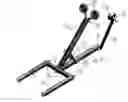
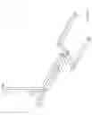
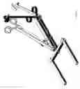
BRIEF DESCRIPTION OF THE SEVERAL VIEWS OF THE DRAWINGRefer to FIG. 1
BASE: The base houses the spring, anchor points, for lifting arms and lever and has the sliding slot milled in the side.
HINGE: The hinge is the anchor point for the throwing lever.
STABILIZER BAR SLEEVES: The Stabilizer bar sleeves attach the stabilizer bar to the base and the extensions.
STABILIZER BAR: The stabilizer bar hold the extensions and keeps the thrower upright.
STABILIZER BAR EXTENSIONS: The stabilizer bar extensions keeps the thrower from jumping over.
PIVOT PIN: The pivot pin or “L” blot is the anchor point for the release lever.
END CAP: The end cap retains the spring in the base and attaching point for the pivot pin.
SLIDING LIFTING PIN: The sliding lifting pin connects the lifting arms together and pushes them upward.
LIFTING ARMS: The lifting arms pushes the throwing lever up.
THE RELEASE LEVER: The release lever locks the throwing lever to the base with the notch and tab.
IMPACT TARGET CUP MOUNTING SLEEVE: This holds the interchangeable primary target.
150 lb. COMPRESSION SPRING: Provides the energy for the mechanism to work.
THROWING LEVER: This holds the throwing cup or cups, and lifts to two different adjustments.
LOCKING LEVER TAB: This stores the energy until the lever is activated.
TARGET CUP HOLDER: This is interchangeable in size or in number of cups.
IMPACT TARGET CUP: This is interchangeable in size and in materials.
DETAILED DESCRIPTION OF THE INVENTIONThe building process will involve cutting, drilling, milling, and welding to manufacture this item.
The materials list includes the following:
| Quantity | Size | Material |
| 2 | 1.5″ × 19.5″ | Square tubing .125″ wall |
| 3 | 1.5″ × 1.5″ × 1.5″ | Square tubing .125″ wall |
| 3 | 1″ × 1″ × 14″ | Square tubing .125″ wall |
| 1 | 3″ × 1″ | Round tubing .125″ wall |
| 1 | 3″ × 1″ | Round tubing .1875″ wall |
| 2 | .75″ × 1.5″ | Round tubing .1875″ wall |
| 1 | 1″ × 18.5″ × .250″ | Flat strap |
| 2 | .75″ × 7″ × .1875″ | Flat strap |
| 3 | 1.75″ × 2.250″ × .3125″ | Flat strap |
| 1 | 1″ × 7″ × .250″ | Flat strap |
| 1 | .375″ × .5″ × .250″ | Flat strap |
| 4 | .375″ × 2.5″ | Solid Rod |
| 3 | .375″ × 1″ | Bolt with nut |
| 1 | .125″ × 3″ | Disc |
| 1 | .1875″ × 3″ | Disc |
| 2 | .375″ × 3″ | Clevis pin |
| 3 | 1″ | Retainer Pin |
| 1 | 1″ × 12″ | 150 lb. Compression spring |
The base #1 is made from 1.5″×1.5″×19.5″ square tubing. One end is notched. 2.250 across the width of one side. The notch is for the hinge to be welded in. The hinge #2 is made with 1.250×0.750″ round tube with a 0.1875″ wall and 1.250″×0.250″ flat strap. The round tube is welded along the top edge of the strap.
Once the hinge is welded in, the stabilizer can be welded on. The sleeve will have a 0.375″ hole in front on center with a nut welded over it. A 0.375″×1″ bolt can be screwed on. This will lock the stabilizer bar #4 on. The stabilizer bar extensions #5 are 1″×1″×14″ square tubing. 125″ wall. On one end a 1.5″×1.5″×1.5″ square tubing is welded perpendicular to the 14″ shaft. This is a sleeve #3 for the stabilizer bar extension to attach the stabilizer bat. These two sleeves need a 0.375″ hole with a nut welded over the hole. A 1″ bolt can be screwed on each one.
The slot for the sliding pin is milled 0.375″ wide, and 5″ long centered on the side of the base. The slot begins 4.750″ from the hinge end. The opposite end of the hinge end is the locking lever pivot point.
The pivot pin #6 is a 0.375:×2.5″ rod bent into a “L” shape, and welded to a 2.250″×1.250″×0.250″ flat strap. The flat strap #7 needs a 0.375″ hole drilled 0.3125″ from the end on center for the pivot pin to be aligned and welded into position.
A 0.375″×2.5″ rod #8 is installed into the milled slot of the base, and the lifting arms #9 are welded onto the rods ends. The rod and arms are welded into a “U” shape.
The release lever #10 is 1″×18.5″×0.250″ flat strip with a 0.375″ hold drilled 0.50″ from the end. The corners are rounded to allow the lever to fall freely on the “L” rod. A 0.250″×0.250″ notch is cut 1″ above the hole. On the other end of the lever a 0.750″×1.5″ tube 0.1875″ wall is welded along the top edge. This will be the impact target cup mounting point.
The 150 lb. compression spring #12 is installed through the pivot point end, and the “L” rod and release lever and end cap strap are installed and welded on.
The throwing lever #13 is 1.5″×1.5″×19.5″ square tubing. 125″ wall. A hole is drilled on one end for the hinge pin. This hole will be 0.375″ and in a corner 0.5″ from the end, and 0.5″ from the bottom. Another 0.375″ hoe is drilled 3.750″ from the hinge pin hole on center. From the hole (light tension setting) another 0.375″ hole is drilled 1.5″ center to center (heavy tension setting).
The locking lever end is opposite of the hinge end and it needs the locking lever tab #14 welded on. The locking lever is 0.375″×0.5″×0.250″ flat strap. This is welded on the same side of the locking lever is located on. The tab is flat with the bottom 0.250″ from the end. From this end, 2″ on center a 0.375″ hole is drilled. This is to hold the target holder cup in place.
The target holder cup #15 is 3″×1″ round tubing 0.125″ wall and a 0.125″×3″ disc with a 1″×7″×0.250″ flat strap. One end of the strap has a 3″ disc 0.135″ thick welded perpendicular to the strap. This strap ends in the enter of the disc. On top of the disc, the 3″ round tube is welded.
The impact target cup #16 is made up of a 0.1875″×3″ disc, and a 3″ diameter 1″ long 0.1875″ wall pipe, and a 0.375″×2.5″ solid rod. The disc and pipe are welded together to form a cup, and the rod is welded perpendicular on the back on center. The rod has a 0.0625″ hole 0.250″ from the end to receive a retainer pin. This pin locks the target cup to the release lever.
The throwing lever is capable of holding two target hold cups. Th is enables two targets in the air to shoot.
Install the stabilizer bar with the stabilizer bar extensions. Be sure to tighten the bolts.
Install the thrower cup onto the throwing lever and use a 0.375″×2.5″ clevis pin to lock it on the lifting arms need to be aligned on the light or heavy tension setting, and clevis pin install with a retainer pin.
While holding the locking lever, press down on the throwing lever, and lock it in place, the locking lever and locking tab should be secure.
Place a target object on the throwing cup.
The target jumper is ready to engage with a weapon or weapons.
The impact target cup can be replaced with a different size, or different materials to the needs of the shooter. For instance, and archery type disc with a pin on the back can be used to catch the arrows and release the locking lever.
Claims
1. I make the claim that this is the first and only device that is triggered be an initial shot to activate the thrower.
I claim this to be solely my idea and design.
I claim all manufactured rights to this product.
Images & Drawings included:
Sources:
- United States Patent and Trademark Office - verify current appl. status at the USPTO↗
Recent applications in this class:
- » 20240219155 2024-07-04
POPPER TARGET SYSTEM - » 20240191977 2024-06-13
REMOTE RESETTING SPORTS TARGET - » 20240035783 2024-02-01
REACTIVE FIREARM TARGET - » 20230417518 2023-12-28
Knockdown-Field-Target Resetting System - » 20230408229 2023-12-21
Self Leveling Target Holder - » 20230392907 2023-12-07
SHOOTING TARGET - » 20230324151 2023-10-12
Axial reset target - » 20220290950 2022-09-15
REACTIVE TARGET SYSTEM, METHOD AND KIT INCLUDING REACTIVE TARGET FOR SIMULATED AMMUNITION - » 20220236039 2022-07-28
TARGET MOUNTING SYSTEM AND METHOD OF USE - » 20210404776 2021-12-30
Modular target structure