Tire ply forming apparatus and process
US20050183815A1
2005-08-25
10/786,805
2004-02-25
Abstract:
A tire ply forming apparatus includes: a roller mechanism for unwinding a narrow ribbon-shaped ply cord from a roll of the ply cord as conveying the unwound ply cord; a cutter for cutting the unwound ply cord into the strip of a length conforming to a tire width; a bonding drum on which the strips are sequentially bonded to each other along a predetermined direction and at a predetermined pitch; transfer device for transporting the strip from a cutting position to the bonding drum; controller for driving-wise controlling the bonding drum to permit the strips to be bonded to each other in a manner that the strips are overlapped with each other to form a predetermined amount of overlap at their longitudinal edges; and a pressure roller for pressing down on the overlap portion of the strips.
Interested in similar patents?
Get notified when new applications in this technology area are published.
Classification:
B29D30/42 » CPC main
Producing pneumatic or solid tyres or parts thereof; Pneumatic tyres or parts thereof (e.g. produced by casting, moulding, compression moulding, injection moulding, centrifugal casting); Textile inserts, e.g. cord or canvas layers, for tyres ; Treatment of inserts prior to building the tyre Endless textile bands without bead-rings
B29C65/00 » CPC further
Joining of preformed parts ; Apparatus therefor
B29C66/1284 » CPC further
General aspects of processes or apparatus for joining preformed parts; General aspects dealing with the joint area or with the area to be joined; Particular design of joint configurations particular design of the joint cross-sections; Joint cross-sections combining only two joint-segments; Tongue and groove joints; Tenon and mortise joints; Stepped joint cross-sections; Stepped joint cross-sections comprising at least one butt joint-segment
B29C66/435 » CPC further
General aspects of processes or apparatus for joining preformed parts; General aspects of joining substantially flat articles, e.g. plates, sheets or web-like materials; Making flat seams in tubular or hollow articles; Joining single elements to substantially flat surfaces; Joining substantially flat articles ; Making flat seams in tubular or hollow articles; Joining a relatively small portion of the surface of said articles Making large sheets by joining smaller ones or strips together
B29C66/72141 » CPC further
General aspects of processes or apparatus for joining preformed parts characterised by the composition, physical properties or the structure of the material of the parts to be joined; Joining with non-plastics material characterised by the structure of the material of the parts to be joined; Fibre-reinforced materials characterised by the length of the fibres Fibres of continuous length
B29C66/73752 » CPC further
General aspects of processes or apparatus for joining preformed parts characterised by the composition, physical properties or the structure of the material of the parts to be joined; Joining with non-plastics material characterised by the intensive physical properties of the material of the parts to be joined, by the optical properties of the material of the parts to be joined, by the extensive physical properties of the parts to be joined, by the state of the material of the parts to be joined or by the material of the parts to be joined being a thermoplastic or a thermoset characterised by the state of the material of the parts to be joined uncured, partially cured or fully cured the to-be-joined area of at least one of the parts to be joined being uncured, i.e. non cross-linked, non vulcanized the to-be-joined areas of both parts to be joined being uncured
B29C66/81465 » CPC further
General aspects of processes or apparatus for joining preformed parts; General aspects of machine operations or constructions and parts thereof; General aspects of the pressing elements, i.e. the elements applying pressure on the parts to be joined in the area to be joined, e.g. the welding jaws or clamps characterised by the design of the pressing elements, e.g. of the welding jaws or clamps characterised by the constructional aspects of the pressing elements, e.g. of the welding jaws or clamps comprising a plurality of single pressing elements, e.g. a plurality of sonotrodes, or comprising a plurality of single counter-pressing elements, e.g. a plurality of anvils, said plurality of said single elements being suitable for making a single joint one placed behind the other in a single row in the feed direction
B29C66/8242 » CPC further
General aspects of processes or apparatus for joining preformed parts; General aspects of machine operations or constructions and parts thereof; Pressure application arrangements, e.g. transmission or actuating mechanisms for joining tools or clamps; Actuating mechanisms Pneumatic or hydraulic drives
B29C66/8362 » CPC further
General aspects of processes or apparatus for joining preformed parts; General aspects of machine operations or constructions and parts thereof characterised by the movement of the joining or pressing tools; Moving relative to and tangentially to the parts to be joined, e.g. transversely to the displacement of the parts to be joined, e.g. using a X-Y table Rollers, cylinders or drums moving relative to and tangentially to the parts to be joined
B29D2030/241 » CPC further
Producing pneumatic or solid tyres or parts thereof; Pneumatic tyres or parts thereof (e.g. produced by casting, moulding, compression moulding, injection moulding, centrifugal casting); Building tyres by the flat-tyre method, i.e. building on cylindrical drums; Drums Auxiliary drums used for temporary storage of the layers before application to the building drums
B29L2030/003 » CPC further
Pneumatic or solid tyres or parts thereof Plies; Breakers
Y10T156/1075 » CPC further
Adhesive bonding and miscellaneous chemical manufacture; Methods of surface bonding and/or assembly therefor with cutting, punching, tearing or severing; Prior to assembly of plural laminae from single stock and assembling to each other or to additional lamina
Y10T156/12 » CPC further
Adhesive bonding and miscellaneous chemical manufacture Surface bonding means and/or assembly means with cutting, punching, piercing, severing or tearing
B29C66/71 » CPC further
General aspects of processes or apparatus for joining preformed parts characterised by the composition, physical properties or the structure of the material of the parts to be joined; Joining with non-plastics material characterised by the composition of the plastics material of the parts to be joined
B29K2021/00 » CPC further
Use of unspecified rubbers as moulding material
Description
BACKGROUND OF THE INVENTION1. Field of the Invention
The present invention relates to a tire ply forming apparatus for forming a tire ply for vehicle from a narrow ribbon-shaped ply cord, and to a tire ply forming process.
2. Background Art
A tire ply for use in a green tire, such as a carcass ply, is conventionally manufactured as follows, in general. First, a plurality of fiber cords is subjected to a dipping machine to produce dipped cords. Then, the dipped cords are processed with a rubber mixture by a topping calendar machine to produce a sheet of rubber-topped cord in a large width dimension of about 1 m.
The sheet of rubber-topped cord is cut into wide ply cord sheets or ply cord, of a width conforming to a tire width. The wide ply cords thus cut are bonded to each other at their ends in a circumferential direction of a tire in a form of ribbon. The resultant band-shaped ply cord is wound into a roll which is temporarily stored. In a ply forming step, the wide ribbon-shaped ply cord is unwound from the roll so as to be conveyed. The ply cord is cut into pieces of a length required for forming individual tires (the length equivalent to a circumference of the tire). Subsequently, the resultant cord piece is stuck to a tire building drum thereby to form a ply.
However, the tire ply varies in length or width depending upon the size of a tire to be built. This dictates the need for preparing plural kinds of rolls of wide ribbon-shaped ply cords in correspondence to the different sizes or specifications of tires. For the purpose of keeping a huge stock of many kinds of rolls, a manufacturing facility is expanded in scale so as to provide a space to store the rolls. In addition, a huge number of management steps are required. That is, it is difficult to manufacture small batches of different types of tires.
As an improvement of the prior art for overcoming the above problem, there is known a process for forming a ply member as disclosed in JP-4(1992)-226742A. According to the process, plural ribbon-shaped members of a constant length are sequentially stuck to the overall peripheral surface of the tire building drum. Specifically, the ribbon-shaped members are sequentially stuck to the tire building drum as positioned to direct their opposite edges parallel to an axis of the tire building drum. On the periphery of the tire building drum, a respective pair of adjoining ribbon-shaped members are forcibly pulled to each other along a circumferential direction of the tire building drum, so as to be bonded to each other at their edge faces or in end-to-end relation. This negates the need for preparing plural kinds of ribbon-shaped members of different widths, offering a solution to the problem associated with the storage space.
However, even the above improved prior-art has the following problem. The ribbon-shaped members are bonded to each other with their ends connected in end-to-end relation. This leads to a problem that a sufficient bonding strength at the bonded portion is not ensured. In particular, a tire building procedure includes a step of inflating the ply stuck to the tire building drum. The step involves a fear that a tire having desired performances may not be built if the bonded portion is poor in the bonding strength.
In view of the foregoing, it is intended to provide a ply forming apparatus and process ensuring the sufficient bonding strength in a tire ply at joints between narrow strips (ribbon-shaped members) bonded to each other at their longitudinal edges.
SUMMARY OF THE INVENTIONAccording to the invention for solving the above problem, a ply forming apparatus comprises: a feeder for unwinding a narrow ribbon-shaped ply cord from a roll of the ply cord as conveying the unwound ply cord; cutting means for cutting the unwound ply cord into a strip having a length conforming to a tire width; a bonding base on which the strips are sequentially bonded to each other along a predetermined direction and at a predetermined pitch; transfer device for transporting the strip from a cutting position to the bonding base; controller for driving-wise controlling the bonding base to permit the strips to be bonded to each other in a manner that the strips are overlapped with each other to form a predetermined amount of overlap along their longitudinal edges; and pressing device for pressing down on the overlap portion of the strips.
The ply forming apparatus has the following operating effects. First, the apparatus unwinds the narrow ribbon-shaped ply cord from the roll of the ribbon-shaped ply cord so as to convey the unwound ply cord. Subsequently, the apparatus cuts the ply cord into the strip having the length conforming to the tire width. The apparatus can cope with tires having different sizes or the like by varying the length of the strip. Thus, the apparatus is adapted for the production of small batches of tires of different types.
The strips thus cut are sequentially bonded to each other on the bonding base. The strips are sequentially bonded to each other at a predetermined pitch in a manner that the strips are overlapped with each other to form a predetermined amount of overlap at their longitudinal edges. The apparatus is provided with the pressing device for pressing down on the above overlap portion. The pressing device ensures that the overlap portion attains a sufficient bonding strength. Specifically, when the strips are sequentially bonded to each other, the strips are overlapped with each other at their longitudinal edges rather than simply connected to each other in end-to-end relation. In consequence, there is provided the ply forming apparatus which is capable of achieving the sufficient bonding strength of the ply formed by bonding the narrow strips or ribbon-shaped members to each other at their longitudinal edges.
According to a preferred embodiment of the invention, the pressing device comprises a plurality of pressure rollers arranged along the overlap portion.
The pressing operation can be quickly and effectively accomplished by virtue of the provision of the plural pressure rollers.
According to another preferred embodiment of the invention, the apparatus further comprises roller moving device for moving the plural pressure rollers along the longitudinal direction.
A more effective pressing operation can be accomplished by moving the plural pressure rollers along the longitudinal direction of the strip.
According to the invention for solving the above problem, a tire ply forming process comprises the steps of: unwinding a narrow ribbon-shaped ply cord from a roll of the ply cord as conveying the unwound ply cord; cutting the unwound ply cord into a strip having a length conforming to a tire width; transporting the strip from a cutting position to a bonding base; sequentially bonding the strips to each other along a predetermined direction and at a predetermined pitch, the strips bonded to each other as overlapped with each other to form a predetermined amount of overlap at their longitudinal edges; and pressing down on such overlap portion of the strips.
The working effects provided by the process are those mentioned supra.
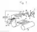
BRIEF DESCRIPTION OF THE DRAWINGSFIG. 1 is a conceptual diagram illustrating an arrangement of a ply forming apparatus;
FIG. 2 is a diagram showing details of pressing device; and
FIG. 3 is a flow chart representing steps of forming a ply.
DETAILED DESCRIPTION OF THE INVENTIONA tire ply forming apparatus according to a preferred embodiment of the invention will be described with reference to the accompanying drawings. FIG. 1 is a conceptual diagram illustrating an arrangement of the tire ply forming apparatus.
<Ply Forming Apparatus>
As shown in FIG. 1, the apparatus includes: a strip roll 1 comprising a narrow ribbon-shaped ply cord 10 wound into a roll; a cutter 2 for cutting the ply cord 10 unwound from the roll 1 into a strip 11 having a predetermined dimension; a bonding drum 4; and transfer device 3 that suction-wise attaches the strip 11 cut off by the cutter 2 and then transfers the strip onto an outer periphery surface of the bonding drum 4 (a kind of bonding base), where the bonding is to be taken place.
The narrow ribbon-shaped ply cord 10 may be produced by the known method, as in a same manner with the method for producing a wide ribbon-shaped ply cord. That is, the ply cord 10 is produced by applying rubber coating on a plurality of fiber cords. The ribbon-shaped ply cord 10 is small in width such as to provide for the production of small batches of various types of tires. The ribbon-shaped ply cord 10 produced in the aforementioned manner is temporarily wound into the roll 1 before committed to storage. The ribbon-shaped ply cord 10 is unwound from the roll 1 when a ply forming process is carried out. The apparatus is further provided with a feeder for unwindingly conveying the ply cord.
The a feeder may have the known arrangement which includes a plurality of roller mechanisms 5 disposed along a conveyance passage of the ribbon-shaped ply cord 10. The a feeder further includes a festoon 6 for speed control. The festoon is free to move up or down. The roll 1 is connected with an unillustrated electric motor at its center of rotation 1a. The cutter 2 operates to cut the ribbon-shaped ply cord 10 into the strip 11. The cutter is adapted to vary the longitudinal length of the strip 11 to be cut. That is, the ribbon-shaped ply cord 10 is cut into a length conforming to a tire width. It is noted that “the length conforming to the tire width” does not mean a length equal to the tire width.
The transfer device 3 includes a vacuum chuck mechanism (not shown) formed with a chuck face on a side facing the strip 11. The vacuum chuck mechanism employs a known mechanism for suction-wise attaching the strip 11 to a predetermined place of the chuck face.
Although not shown in the figure, the transfer device 3 is provided with a mechanism for moving up or down the transfer device 3 so as to attach the strip 11, and a mechanism for transeversely moving the transfer device 3 as to transport the attached strip 11 from a cutting position to the bonding drum 4. The bonding drum 4 is driven into rotation about a center of rotation thereof 4a by means of an unillustrated electric motor.
Controller 7 essentially comprises a computer and a computer program. The controller 7 controls the operations of the transfer device 3 and the bonding drum 4.
On the bonding drum 4, the strips 11 supplied by the transfer device 3 are sequentially bonded to each other in a manner that the strips are overlapped with each other to form a predetermined amount of overlap at their longitudinal edges. The bonding drum 4 is provided with pressing device 20 for pressing down on the overlap portion. A ply sheet 12 is formed by sequentially bonding the strips 11 to each other. The ply sheet 12 is conveyed by a conveyance mechanism so as to be fed to a tire building drum 8. Similarly to the conveyance of the ply cord 10, the conveyance mechanism may adopt a known structure.
When a length of ply sheet 12 constituting a tire body is stuck onto the tire building drum 8, the ply sheet 12 is cut off. The operation of sticking the ply sheet 12 onto the tire building drum 8 may be carried out the same way as in the conventional method. Subsequently, a predetermined procedure (the explanation thereof is omitted) is taken to manufacture a green tire.
<Construction of Pressing Device>
FIG. 2 is a diagram showing details of the pressing device. The pressing device 20 includes a plurality of pressure rollers 21 arranged along the longitudinal overlap portion of the edges of the strips. The pressing device further includes a guide 22 that also has a function to support the pressure rollers 21. The guide 22 has an inverse U-shape in cross section such as to provide a widthwise support for the pressure rollers 21. Furthermore, the guide is adapted to move along the longitudinal direction (the direction of Arrow A). As associated with the guide, the plural pressure rollers 21 are also allowed to move along the direction of Arrow A. Thus, the pressure rollers can uniformly press down on the whole area of the overlap portion, thereby making the bond between the strips 11 stronger. After pressed, the bonded strips form a flat ply sheet free from surface irregularities.
A first actuator cylinder 23 and a second actuator cylinder 24 are provided for driving the pressing device 20. The second actuator cylinder 24 and the guide 22 may be moved along the direction of Arrow “A” by driving the first actuator cylinder 23 (as indicated by Arrow “B”). The second actuator cylinder 24 may be driven to push down the guide 22 (the direction of Arrow “C”) thereby effectively applying the pressing force via the pressure rollers 21.
<Ply Forming Process>
Next, a procedure for forming the ply will be described with reference to a flow chart of FIG. 3.
First, the ribbon-shaped ply cord is sequentially unwound from the strip roll 1 (#1). Determination is made as to whether a predetermined length of ply cord 10 from the cutting position of the cutter 2 is fed out or not (#2). The control may be performed based on a pulse signal outputted from an encoder directly or indirectly coupled or connected with a roller mechanism 5. The predetermined length of the ply cord is decided based on a tire size or specifications of the tire. When the predetermined length of ply cord is fed out, the conveyance of the ply cord is temporarily suspended (#3) Then, the cutter 2 is actuated to cut the ribbon-shaped ply cord 10 into the strip 11 (#4).
Next, the transfer device 3 is actuated for suction-wise attaching the strip 11 to the chuck face thereof (#5). The transfer device 3 is driven to transport the strip 11 from the cutting position to the bonding drum 4 (#6). Subsequently, the strip 11 is released from the attached state so as to be placed on the bonding drum 4 (#7). The strip 11 is placed on the bonding drum in a manner that a longitudinal edge of the newly placed strip 11 is overlapped with that of the preceding strip 11. Meantime, the transfer device 3 is returned to its initial position as to suction-wise attach the succeeding strip 11.
Next, the pressing device 20 is actuated to press down on the overlap portion (#8). First, the second actuator cylinder 24 is driven to apply the pressing force to the pressure rollers 21. In this state, the first actuator cylinder 23 is driven. This brings the guide 22 into movement along the longitudinal direction. Accompanying with the movement, the pressure rollers 21 are moved as to roll along the longitudinal direction. As a result, the pressure is uniformly applied to the overlap portion so as to strengthen the bonded joint.
At completion of the pressing operation, the bonding drum 4 is rotated by a predetermined amount (angle) (#9). This permits the drum to receive the next strip 11 to be bonded. Subsequently, the same procedure may be repeated.
Other Preferred EmbodimentsAccording to the embodiment of the invention, various modifications may be made to the elements constituting the tire ply forming apparatus. For instance, the bonding base is exemplified by the bonding drum but is not limited to this. Alternatively, a belt conveyor may be employed for bonding purpose. In this case, the strips are bonded to each other on a flat surface. Furthermore, the pressing device may employ a member having a flat pressing face in place of the roller. The amount of overlap of the strips may be defined properly in accordance with specific condition or requirement.
- CONTROLLER
- #1 UNWIND PLY CORD FROM A ROLL
- #2 UNWOUND TO A PREDETERMINED LENGTH?
- #3 SUSPEND TRANSPORTATION OF PLY CORD
- #4 CUT PLY CORD
- #5 SUCK PLY CORD
- #6 TRANSPORT PLY CORD
- #7 PLACE PLY CORD ON BONDING DRUM
- #8 OPERATE PRESSING DEVICE
- #9 ROTATE BONDING DRUM BY A PREDETERMINED AMOUNT
Claims
1. A ply forming apparatus comprising:
a feeder for unwinding a narrow ribbon-shaped ply cord from a roll of the ply cord as conveying the unwound ply cord;
cutter for cutting said unwound ply cord into a strip of a length substantially conforming to a tire width;
a bonding base on which said strips are sequentially bonded to each other along a predetermined direction and at a predetermined pitch;
transfer device for transporting said strip from a cutting position to the bonding base;
controller for driving-wise controlling said bonding base to permit said strips to be bonded to each other in a manner that the strips are overlapped with each other to form a predetermined amount of overlap along their longitudinal edges; and
pressing device for pressing down on such overlap portion of said strips.
2. A ply forming apparatus as claimed in claim 1, wherein said pressing device comprises a plurality of pressure rollers arranged along said overlap portion.
3. A ply forming apparatus as claimed in claim 2, further comprising roller moving device for moving said plural pressure rollers along the longitudinal direction.
4. A ply forming process comprising the steps of:
unwinding a narrow ribbon-shaped ply cord from a roll of the ply cord as conveying the unwound ply cord;
cutting said unwound ply cord into a strip having a length substantially conforming to a tire width;
transporting said strip from a cutting position to a bonding base;
sequentially bonding said strips along a predetermined direction and at a predetermined pitch, said strips bonded to each other as overlapped with each other to form a predetermined amount of overlap along their longitudinal edges; and
pressing down on such overlap portion of said strips.
Images & Drawings included:


Sources:
- United States Patent and Trademark Office - verify current appl. status at the USPTO↗
Recent applications in this class:
- » 20210162695 2021-06-03
Tire carcass ply joining apparatus and method - » 20190270265 2019-09-05
Joining device and method for joining strips to form a tire component - » 20170239901 2017-08-24
Device and method for butt-splicing strip members - » 20170072652 2017-03-16
Tire carcass ply joining apparatus and method - » 20130160687 2013-06-27
Stitcher and method for stitching together strips of rubber material - » 20120132347 2012-05-31
MACHINES AND METHODS FOR MANUFACTURING OF AN OBJECT CLOSED ONTO ITSELF - » 20120080139 2012-04-05
Rubber sheet jointing apparatus and method - » 20120067516 2012-03-22
Device for transferring and aligning strips intended to be assembled to form a ply - » 20110192538 2011-08-11
Device and method for manufacturing sheet with cords - » 20110146887 2011-06-23
TIRE PLY AND METHOD OF MANUFACTURE