Oxygen-enriched feedgas for reformer in emissions control system
US20050193724A1
2005-09-08
11/067,815
2005-02-28
Abstract:
A method and systems for supplying oxygen-enriched feedgas to a reformer. The reformer is placed on an exhaust bypass line, which has a valve upstream the reformer, for opening and closing the flow of exhaust gas into the bypass line. The bypass line receives atmospheric air at a venturi, and this air is mixed with the exhaust gas to supply feedgas to the reformer. The output of the reformer is directed via the bypass line to a point on a main exhaust line upstream an emissions control device, such as a NAC.
Inventors:
- Cynthia C. Webb 10 🇺🇸 San Antonio, TX, United States
- Joseph W. Anthony 6 🇺🇸 Lytle, TX, United States
Assignee:
- SOUTHWEST RESEARCH INSTITUTE 594 🇺🇸 San Antonio, TX, United States
Interested in similar patents?
Get notified when new applications in this technology area are published.
Classification:
F01N3/0842 » CPC main
Exhaust or silencing apparatus having means for purifying, rendering innocuous, or otherwise treating exhaust for rendering innocuous by using absorbents or adsorbents characterised by the absorbed or adsorbed substances Nitrogen oxides
F01N3/0878 » CPC further
Exhaust or silencing apparatus having means for purifying, rendering innocuous, or otherwise treating exhaust for rendering innocuous by using absorbents or adsorbents; Regulation of absorbents or adsorbents, e.g. purging Bypassing absorbents or adsorbents
F01N3/22 » CPC further
Exhaust or silencing apparatus having means for purifying, rendering innocuous, or otherwise treating exhaust for rendering innocuous by thermal or catalytic conversion of noxious components of exhaust characterised by methods of operation; Control Control of additional air supply only, e.g. using by-passes or variable air pump drives
F01N3/30 » CPC further
Exhaust or silencing apparatus having means for purifying, rendering innocuous, or otherwise treating exhaust for rendering innocuous by thermal or catalytic conversion of noxious components of exhaust characterised by constructional aspects of converting apparatus Arrangements for supply of additional air
F01N9/00 » CPC further
Electrical control of exhaust gas treating apparatus
F02B37/00 » CPC further
Engines characterised by provision of pumps driven at least for part of the time by exhaust
F01N3/021 » CPC further
Exhaust or silencing apparatus having means for purifying, rendering innocuous, or otherwise treating exhaust for cooling, or for removing solid constituents of, exhaust by means of filters
F01N13/107 » CPC further
Exhaust or silencing apparatus characterised by constructional features ; Exhaust or silencing apparatus, or parts thereof, having pertinent characteristics not provided for in, or of interest apart from, groups - , ,; Other arrangements or adaptations of exhaust conduits of exhaust manifolds More than one exhaust manifold or exhaust collector
F01N2240/30 » CPC further
Combination or association of two or more different exhaust treating devices, or of at least one such device with an auxiliary device, not covered by indexing codes or , one of the devices being a fuel reformer
F01N2560/025 » CPC further
Exhaust systems with means for detecting or measuring exhaust gas components or characteristics the means being an exhaust gas sensor for measuring or detecting O, e.g. lambda sensors
Y02T10/12 » CPC further
Road transport of goods or passengers; Internal combustion engine [ICE] based vehicles Improving ICE efficiencies
Y02T10/12 » CPC further
Road transport of goods or passengers; Internal combustion engine [ICE] based vehicles Improving ICE efficiencies
Y02T10/40 » CPC further
Road transport of goods or passengers; Internal combustion engine [ICE] based vehicles Engine management systems
Y02T10/40 » CPC further
Road transport of goods or passengers; Internal combustion engine [ICE] based vehicles Engine management systems
Description
RELATED PATENT APPLICATIONThis application claims the benefit of U.S. Provisional Application No. 60/548,354, filed Feb. 27, 2004 and entitled “Oxygen-Enriched Feedgas for Reformer in NOx Adsorber Emissions System”.
TECHNICAL FIELD OF THE INVENTIONThis invention relates to reducing exhaust emissions from internal combustion engines, and more particularly to providing oxygen-enriched feedgas for an exhaust gas reformer used upstream of an emissions control device, such as a lean NOx catalyst.
BACKGROUND OF THE INVENTIONInternal combustion engines are a major contributor to harmful emissions. Internal combustion engines dominate land transportation propulsion—cars, trucks, off-highway vehicles, railroad, marine, motorcycles—as well as provide mechanical and electrical power for a wide range of large and small applications. The two dominant types of internal combustion engines are spark-ignition and diesel. The amount and composition of the emissions exhausted from these engines depend on the details of the processes that occur within the engine during operation, the characteristics of the fuel used, and the type of emissions control system used.
For diesel engines, the main pollutants of concern are nitrogen oxides (NOx) and particulate matter (PM). The latter is composed of black smoke (soot), sulfates generated by the sulfur in fuel, and organic components of unburned fuel and lubricating oil.
In-cylinder design changes have had some success in reducing emissions, but have fallen short of allowing diesel engines to meet today's emissions limits. Post-combustion treatment systems often include catalysts and particulate filters for reducing NOx and PM respectively. Technology advances in the catalyst field have made it possible for integrated systems of engine and exhaust treatment to achieve extremely low emissions. Yet, more emission reduction efficiencies are sought from existing systems and new catalytic reduction solutions are needed to achieve even lower emissions.
Indications are that diesel oxidation catalyst performance improves with increased engine speed, airflow, and hence oxygen content. For particulate filters, both oxygen content and exhaust gas temperature their regeneration.
On the other hand, for regeneration of modern NOx reduction catalysts such as the lean NOx trap (NOx adsorber catalyst), reduced oxygen content in the exhaust is desirable. Normally in diesel exhaust, attempts are made to reduce oxygen to regenerate the system from its stored nitrogen compounds. Attempts to reduce exhaust oxygen content are usually combined with increasing exhaust hydrocarbon to obtain the rich mixture needed for the NOx regeneration process.
It is customary in diesel NOx adsorber technology to place a diesel oxidation catalyst upstream from the lean NOx trap. Its purpose is to condition the exhaust hydrocarbon or reform it to obtain the ideal reductant for the lean NOx trap regeneration.
Having established the need for controlling the composition of the reductant, some companies have announced plans for using onboard fuel reformers to accomplish their needs. Onboard fuel reformers involve some kind of catalyst that is provided with a supply of fuel and a supply of air. Providing a continuous but controllable supply of fuel has not been a significant obstacle. However, providing a suitable supply of air to the reformer has been challenging.
BRIEF DESCRIPTION OF THE DRAWINGSA more complete understanding of the present embodiments and advantages thereof may be acquired by referring to the following description taken in conjunction with the accompanying drawings, in which like reference numbers indicate like features, and wherein:
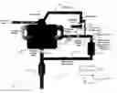
FIG. 1 illustrates a first embodiment of the invention; and
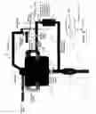
FIG. 2 illustrates a second embodiment of the invention.
DETAILED DESCRIPTION OF THE INVENTIONThe following description is directed to an engine-based means and method, used in conjunction with a diesel emissions control system, for supplying an exhaust reformer with a source of air. The air enriches the feedgas to the reformer, which generates a reformate. In the example of this description, the enriched feedgas is used by the reformer to provide a reductant during regeneration of a NOx adsorbtion catalyst (NAC).
FIG. 1 illustrates a method and system for supplying air to a reformer 101 in accordance with the invention. Reformer 101 is part of an emissions control system 100, which also has at least one emissions control device 102 that has cause to use feedgas from reformer 101. In the example of this description, the emissions control device 102 is a NAC (NOx adsorber catalyst) sometimes also referred to as an LNT (lean NOx trap).
Engine 103 is a diesel engine, and in the example of this description, is a dual bank engine. It is equipped with an air-charging device 104, such as a turbocharger. In the example of this description, turbocharger 104 is a VNT (variable nozzle turbocharger).
The method is particularly useful for supplying oxygen-enriched feedgas to reformer 101 under low flow and/or low load engine operating conditions. Under such conditions, fresh air from a boosted source (such as turbocharger 104) is low or unavailable.
As illustrated, NAC 102 is mounted along the engine exhaust pipe. NAC 102 is essentially a storage device for NOx contained in the exhaust gas. It has two principal elements: a NOx adsorbent and a three-way conversion catalyst. NAC 102 has three primary functions: conversion of NO to NO2, adsorption of NO2, and release and reduction of NO2 during regeneration of the NAC 102.
As stated in the Background, regeneration of NAC 102 is performed under rich exhaust gas conditions. Under such conditions, the stored NOx is released from the adsorbent and simultaneously reduced to N2 (and/or N2O or NH3) over precious metal sites.
Reformer 101 is placed on an exhaust bypass 105. As explained below, the purpose of reformer 101 is to supply reductant for regeneration of the NAC 102. Reformer 101 typically has a catalyst, and is provided with a supply of fuel and a supply of air. A supply line (not shown) may be used to supply fuel or any other liquid or gas consumed by the reformer.
In the example of this description, where engine 103 is a dual-bank engine, exhaust bypass 105 is routed off one side of the exhaust manifold, prior to turbocharger 104. For an in-line engine, the bypass would be installed upstream of the turbocharger. Bypass 105 joins the main exhaust pipe upstream the NAC 102
Exhaust bypass 105 is normally closed, using valve 107. When flow through reformer 101 is desired, and exhaust flow conditions are low, valve 107 blocking the exhaust bypass 105 is opened.
At the same time, the turbocharger 104 is operated to as to obstruct exhaust flow from the turbocharger. For example, the turbine vanes may be closed. Essentially, while exhaust gas is flowing through bypass 105, turbocharger 104 is used to put backpressure on the exhaust flow. If the turbocharger 104 does not sufficiently obstruct exhaust flow, an optional exhaust valve 106 may be closed to increase the flow through the exhaust bypass 105.
Flow through exhaust bypass 105 may be metered by using a metering valve for valve 107. An example of a suitable valve is an EGR (exhaust gas recirculation) metering valve. A venturi 108 is placed downstream valve 107.
A fresh air line 109 is plumbed to the center of venturi 108, which pulls air in. During low flow conditions, the air into venturi 108 is not necessarily charged; charged air is not required for operation of the invention. However, in various embodiments of the invention, charged air may be available and used.
In the example of FIG. 1, fresh air line 109 is routed through the compressor side of turbocharger 104. This permits fresh air line 109 to receive charged air from turbocharger 104 if available and desired. As explained below in connection with FIG. 2, in other embodiments, fresh air line 109 may be routed directly from atmosphere.
The fresh air entering exhaust bypass 105 at venturi 108 provides oxygen-enrichment of the exhaust, which already has a high oxygen content at low load and idle. Under these conditions, the exhaust prior to enrichment already typically has more than 15% oxygen.
The oxygen-enriched gas mixture is then supplied to reformer 101. An example of a suitable reformer 101, is a fuel-based reformer, which burns diesel fuel, and makes the exhaust gas fuel-rich, to be used for regeneration of NAC 102.
Optionally, a small diesel particulate filter 110 can be placed at the entrance to exhaust bypass 105, to clean the exhaust gas. The filter 110 may be placed anywhere upstream reformer 101.
Various sensors, such as mass airflow (MAF) sensor 111 and/or an oxygen sensor 112 can be used to determine an oxygen mass flow rate. This measurement is especially useful for closed-loop control of fuel to the reformer 101. A metering valve 113 may be used to control the amount of oxygen received at venturi 108.
A controller 120 can be used to receive measurements from various sensors, such as sensors 111 and 112. Controller 120 would deliver control signals to various valves, such as valves 107, 106, and 113. Controller 120 would be programmed to perform the method described above, and wherein the emissions control device 102 is a NAC, would be programmed to provide oxygen-enriched feedgas via the bypass line 105 during regeneration of NAC.
FIG. 2 illustrates a second embodiment of the invention, in which fresh air line 209 is routed directly to atmosphere, rather than being routed through the compressor side of turbocharger 204. The embodiment of FIG. 2 operates in the same manner as the embodiment of FIG. 1, being particularly designed for use during low-flow/low-load conditions. It is conceivable that engine 203 may lack a turbocharger or other air-charging device, in which case the above-described method is operable independently of such devices.
Claims
1. A method, for use in a diesel engine having an air-charging device, of providing a reformate to an emissions control device on an exhaust line, comprising:
using a bypass line to carry exhaust gas from the engine to a point on the exhaust line upstream the emissions control device;
opening a valve on the bypass line upstream the reformer;
directing atmospheric air to a venturi in the bypass line, upstream the reformer;
receiving the air and exhaust into the reformer;
using the reformer to generate the reductant; and
routing the reductant, via the bypass line, to the point on the exhaust line upstream the emissions control device.
2. The method of claim 1, further comprising the step of closing the exhaust flow from the air-charging device.
3. The method of claim 1, further comprising the step of using a valve to decrease or stop the flow of exhaust through the exhaust line.
4. The method of claim 1, further comprising the step of using backpressure of the air-charging device to boost flow to the reformer.
5. The method of claim 1, wherein the emissions control device is a NOx adsorption catalyst (NAC), and wherein the method operates during regeneration of the NAC.
6. The method of claim 1, further providing the step of using a sensor to detect the oxygen provided to the reformer.
7. The method of claim 1, wherein the method is used with closed loop control hardware for control of oxygen to the reformer.
8. The method of claim 1, wherein the bypass line begins at a point between the exhaust manifold and the air-charging device.
9. The method of claim 1, wherein the atmospheric air is routed from the air output side of the air-charging device.
10. The method of claim 1, wherein the atmospheric air is routed directed directly from atmosphere.
11. An exhaust system for a diesel engine having an air-charging device, comprising:
an exhaust line for carrying exhaust gas from the engine to atmosphere;
at least one emissions control device on the exhaust line;
a bypass line to carry exhaust gas from the engine to a point on the exhaust line upstream the emissions control device;
a reformer on the bypass line;
a valve on the bypass line upstream the reformer, for opening and closing the flow of exhaust gas from the engine into the bypass line;
a venturi in the bypass line, upstream the reformer; and
an air inlet for receiving air into the bypass line at the venturi;
wherein the air inlet receives air from the air-charging device.
12. The system of claim 11, further comprising a valve for closing the flow of exhaust into the exhaust line.
13. A method, for use in a diesel engine, of providing a reformate to an emissions control device on an exhaust line, comprising:
using a bypass line to carry exhaust gas from the exhaust manifold of the engine to a point on the exhaust line upstream the emissions control device;
opening a valve on the bypass line upstream the reformer;
directing atmospheric air to a venturi in the bypass line, upstream the reformer;
receiving the air and exhaust into the reformer;
using the reformer to generate the reformate; and
routing the reformate, via the bypass line, to the point on the exhaust line upstream the emissions control device.
14. The method of claim 13, further comprising the step of using a valve to decrease or stop the flow of exhaust through the exhaust line.
15. The method of claim 13, wherein the emissions control device is a NOx adsorption catalyst (NAC), and wherein the method operates during regeneration of the NAC.
16. The method of claim 13, further providing the step of using a sensor to detect the oxygen provided to the reformer.
17. The method of claim 13, wherein the method is used with closed loop control hardware for control of oxygen to the reformer.
18. An exhaust system for a diesel engine, comprising:
an exhaust line for carrying exhaust gas from the engine to atmosphere;
at least one emissions control device on the exhaust line;
a bypass line to carry exhaust gas from the engine to a point on the exhaust line upstream the emissions control device;
a reformer on the bypass line;
a valve on the bypass line upstream the reformer for opening and closing the flow of exhaust gas from the engine into the bypass line;
a venturi in the bypass line, upstream the reformer; and
an air inlet for receiving air into the bypass line at the venturi.
19. The system of claim 18, wherein the emissions control device is a NOx adsorber catalyst (NAC).
20. The system of claim 18, further comprising a valve for closing the flow of exhaust into the exhaust line.
Images & Drawings included:

Sources:
- United States Patent and Trademark Office - verify current appl. status at the USPTO↗
Recent applications in this class:
- » 20250163838 2025-05-22
EXHAUST PURIFICATION APPARATUS - » 20240175382 2024-05-30
Reduction of tailpipe emissions from gasoline internal combustion engines with a combination of sorbents - » 20230003150 2023-01-05
Lean NOtrap plus low temperature NOadsorber system for low temperature NOtrapping - » 20220268190 2022-08-25
Systems and methods for controlling exhaust gas aftertreatment sensor systems - » 20220268189 2022-08-25
Systems and methods for controlling exhaust gas aftertreatment sensor systems - » 20220162970 2022-05-26
Low-temperature de-NOx catalyst for treatment of exhaust gas from stationary source and method of manufacturing same - » 20220056829 2022-02-24
Gas engine heat pump - » 20210239019 2021-08-05
Method and systems for engine control - » 20210172357 2021-06-10
Device for screening NOsensor - » 20210062698 2021-03-04
Systems and methods for controlling exhaust gas aftertreatment sensor systems
Recent applications for this Assignee:
- » 20240272068 2024-08-15
Seamless integrating cavity of monolithic fumed silica - » 20240240587 2024-07-18
Power production plant including liquid oxygen storage and method of operation of the power production plant - » 20240141607 2024-05-02
Modular closed loop pumped storage hydropower plant - » 20240103516 2024-03-28
System and method for comparing simulated environments for unmanned ground vehicle development and testing - » 20240079714 2024-03-07
Thermal Runaway Prevention System - » 20240078914 2024-03-07
Navigation system for unmanned aircraft in unknown environments - » 20240011852 2024-01-11
Frictional torque determination technique - » 20240004087 2024-01-04
Center path estimator for agricultural windrows - » 20230390932 2023-12-07
Collaborative Robotic System - » 20230358157 2023-11-09
System and method for reduced nitrous oxide emissions using predictive urea dosing control