Fence tool
US20050194056A1
2005-09-08
10/794,827
2004-03-08
Abstract:
A two piece tool for joining the ends of two wires together includes first tool member which has two openings into which the ends of two wires are inserted. A second tool member has an opening in one end into which both ends of the two wires are inserted. The two parts are rotated, or at least one part is rotated, to twist the ends of the two wires together. If both parts are rotated, they are rotated in opposite directions to twist the ends of the two wires together.
Interested in similar patents?
Get notified when new applications in this technology area are published.
Classification:
B21F15/04 » CPC main
Connecting wire to wire or other metallic material or objects; Connecting parts by means of wire wire with wire without additional connecting elements or material, e.g. by twisting
Description
FIELD OF THE INVENTIONThe invention relates to fence tools, and more particularly to a tool for splicing and repairing fence wires.
BACKGROUND OF THE INVENTIONThe background of the invention is shown in the following patents. These patents are distinct from the invention and are described to show the prior art and the distinctness of the invention from this prior art.
U.S. Pat. No. 4,393,905 defines a wire splicing tool. The tool comprises an elongated, rigid frame, including a pair of outwardly diverging handle ends. A rigid, integral, tubular frame center receives the shank of a rotatable member for controlling wire splicing. The control member includes an external, wire contacting head which forcibly coils wire ends in response to tool rotation. The control shank includes an elongated, wire receptive groove. When the groove is aligned with a slot defined in frame center, capture (or release) of a first wire segment is facilitated. With the first wire captured, the tool may be rotated to coil an end of a second wire about the first.
U.S. Pat. No. 4,057,221 is for a tool for stretching the individual wire strands of a fence from a slack into a taut condition. The tool is left attached to the tightened wire and can subsequently be employed to further tighten or loosen the wire. The tool has a plurality of slots arranged thereon which engage spaced marginal lengths of the wire. A set of spaced tabs are used to secure the tool to the wire to prevent inadvertent unwinding. A removable handle is provided by which the tool is engaged and manipulated in a manner to fold a length of wire between the slots thereof and back upon itself, and thereafter a pair of spaced tabs engage spaced marginal lengths of the wire to prevent the tool from unwinding from the bent-up wire.
U.S. Pat. No. 4,830,065 defines a wire splicing tool for splicing together the ends of single or multiple strand wires, such as the wire used for fence lines, includes a pair of tool members adapted to be set in an interlocked position capturing a straight portion at the end of a first wire extending along a fence line and holding a turned portion at the end of a second wire extending along the fence line for winding the second wire turned portion around the first wire straight portion to effect a splicing action between the two wires
U.S. Pat. No. 5,605,181 defines a Handheld wire twisting apparatus can be readily applied to a working section of an elongated electrical harness to be twisted, operated to impart twist to the desired extent, then removed after the twist has been secured in the harness. It includes a housing with an integral handle. An internal cylindrical bearing surface defines a transverse axis and includes an inlet into a bearing cavity which is a hiatus in the bearing surface. A c-shaped cylindrical wire twisting head is journaled on the cylindrical bearing surface for rotation about the transverse axis and defines a transverse passageway for reception of a wire bundle to be twisted. The wire twisting head has a peripheral gap for reception of the wire bundle into the transverse passageway when the peripheral gap is coextensive with the inlet in the housing. A gear train is rotatably mounted between opposed plate members comprising the housing for rotating the head, selectively, in first and second directions about the transverse axis and a ratchet mechanism selectively preventing rotation of the head in the first and second directions. The wire twisting head includes a c-shaped cylindrical drive wheel, a c-shaped cylindrical socket member having a peripheral opening and adapted for releasable attachment to the drive wheel, and a diametrically extending wire engagement member fixed to the socket member and projecting toward the peripheral opening. Mutually engageable key means on the socket member and on the drive wheel releasably attaches the socket member to the drive wheel.
U.S. Pat. No. 5,752,551 is a single part hand-held tool wire twister including an upper portion having a handle engageable by an operator for imparting a twisting action to the wire twister. A lower portion has a wire strand engaging head that is coupled to the handle by an extension shaft. The wire strand engaging head flares outward from the extension shaft so that a perimeter of the head is greater that a perimeter of the shaft so that the head establishes a wire engaging portion of the wire twister. The wire engaging portion has at least two wire receiving channels cut thereinto for engaging at least two wire strands to be connectively intertwined by rotational motion of the wire twister; each channel engaging one or more wires. Each of the channels extends from an opening at the perimeter of the head toward a center of the head.
SUMMARY OF THE INVENTIONThe fence tool of the present invention is used for installing new fences and repairing existing fences. The tool is a two part tool. A first part has two openings into which the ends of two wires are inserted. A second part has an opening in one end into which both ends of the two wires are inserted. The two parts are rotated, or at least one part is rotated, to twist the ends of the two wires together. If both parts are rotated, they are rotated in opposite directions to twist the ends of the two wires together.
The openings in the ends of the parts are first may be tapered to allow the wires to move into an elongated slot which holds the wires and prevent them from moving or slipping during the twisting of the two wires together.
The technical advance represented by the invention as well as the objects thereof will become apparent from the following description of a preferred embodiment of the invention when considered in conjunction with the accompanying drawings, and the novel features set forth in the appended claims.
BRIEF DESCRIPTION OF THE DRAWINGSFIG. 1 shows an isometric view of one of the fence tool part;
FIG. 2 shows an isometric view another of the fence tool part;
FIG. 3 shows a front view of the fence tool part of FIG. 1;
FIG. 4 is an end view of FIG. 3;
FIG. 5 is a front view of the tool part of FIG. 2;
FIG. 6 is an side view of the tool part of FIG. 5;
FIG. 7 shows the tool of the invention with two wire ends inserted in the openings in the tools;
FIG. 8 shows two tool splicing tow wire ends with a third piece of wire; and
FIG. 9 is an isometric view shown another embodiment of the invention.
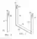
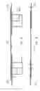
DESCRIPTION OF A PREFERRED EMBODIMENTFIG. 1 shows an isometric view of one part of the fence tool. Tool 10 includes two wire holders 12 and 13. Wire holders 12 and 13 are joined together and separated by a base or handle 11. Wire holders 12 and 13 each have an opening 14 and 16, respectively, in an end that extends to slots 15 and 17, respectively, which hold wire ends during the splicing process. When two pieces of wire are to be spliced together, the two wires are inserted into slots 15 and 17 through the tapered openings 14 and 16.
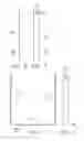
Side view of tool 10 is shown in FIG. 3, and an end view is shown in FIG. 4. The configuration of tool 10 shown in FIGS. 1, 3 and 4 are give by way of example. The exact shape is not critical as long as the wires to be joined are held at spaced apart positions.
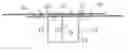
FIG. 2 shows the second part of the fence tool. Tool 20 is similar to a side of tool 10. Tool 20 has a handle 21 that has a tapered opening 22 in one end that extends to slot 23. FIGS. 5 and 6 show side and end views of part 20. In splicing wires, tool 20 is placed between the parts 12 and 13 of tool 10, and the two wires to be joined are place in slot 23. To splice the wires, tool 20 is rotated with respect to tool 10, twisting the two ends of the wires together
FIG. 7 shows the tool of the invention with two wire ends inserted in the openings in the tools. Tool 10 has two wires 31 and 32, each of which is placed in the slots 15 and 17. Tool 20 is placed between the two parts 12 and 13 of tool 10 and placed so that the two wires to be spliced together are in slot 23. Tool 20 is then rotated to twist wires 31 and 32 together.
FIG. 7 shows the basic placement when two ends of two wire are to be fastened together. However, if there is, for example, a break in a fence wire, the two ends of the broken wire may not be extendable to lap over each other as illustrated in FIG. 7. In this situation, a third piece of wire is need to repair the broken wire. FIG. 8 shows the splicing of two wires with a third piece of wire. Only one repair tool is need. First the end of wire 31 and splice wire 33 are placed in tools 10a and 20a, and twisted to join wires 31 and 33 together. Next, the end of wire 32, and the opposite end (opposite from that jointed to wire 31) of wire 33 are placed in tools 10b and 20b. The ends are twisted together to join them together. FIG. 9 shows the resulting splice joining wires 31 and 32 together.
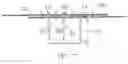
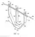
FIG. 10 shows another embodiment of the fence tool. This embodiment is to illustrate that the exact shape of the tool is not relevant as long as the two tools can interact to twist the ends of wire together. In FIG. 10, tool 40 includes a bottom portion 45 that to part 41 which has the tapered opening 48 and wire slot 49. Part 44 extends upward to part 42 that has tapered opening 50 and wire slot 51.
Tool 60 has a bottom portion 61 that is connected to a vertical part 62 that has tapered slot 63 and wire slot 64. Wires 54 and 55 are placed in wire slots 49, 64 and 51, and tool 60 is rotated around the wi shows the tool of the invention with two wire ends inserted in the openings in the tools re 54 and 55, as shown by arrow 70.
The shape of part 40 can be U-shaped or some other configuration s long as the wire slots 49 and 51 are spaced apart and generally parallel so that the wires can extend through the slots 49 and 51.
Claims
1. A two piece wire joining tool, comprising:
a first tool member comprising a pair of members attached together in a spaced-apart relation;
a pair of wire slots, one each in the pair of members; and
a second tool member, said second tool member having a wire slot in one end.
2. The wire joining tool according to claim 1, including tapered sides extending to the slots in each of said first and second tool members.
3. The wire joining tool according to claim 1, wherein said first tool member is generally U-shaped.
4. The wire joining tool according to claim 1, wherein said wire slots in said first and second tool members are of a length to accept at least two wires, one positioned above the other.
5. The wire joining tool according to claim 1, wherein said first tool member is U-shaped.
6. A two piece wire joining tool, comprising:
a first U-shaped tool member comprising a pair of members attached together in a spaced-apart relation;
a pair of wire slots, one each in the pair of members; and
a second tool member, said second tool member having a wire slot in one end.
7. The wire joining tool according to claim 6, including tapered sides extending to the slots in each of said first and second tool members.
8. The wire joining tool according to claim 6, wherein said first tool member is generally U-shaped.
9. The wire joining tool according to claim 6, wherein said wire slots in said first and second tool members are of a length to accept at least two wires, one positioned above the other.
10. The wire joining tool according to claim 6, wherein said U-shaped first tool member is of a length to allow the second tool member to rotate within the first tool member.
Images & Drawings included:
Sources:
- United States Patent and Trademark Office - verify current appl. status at the USPTO↗
Similar patent applications:
- » 20230226668
Fencing Tool - » 20130227793
Fencing tool - » 20190003204
Fencing tool - » 20250065530
CUTTING TOOL FENCE APPARATUS WITH MEASURING RULER AND MOVEABLE MATERIAL STOP COMPONENT - » 20120073060
Fencing tool - » 20130299619
Fencing tool - » 20090028649
Silt fence removal tool - » 20220220769
Fence Repair Tool and Method - » 20120247060
INSTALLATION TOOL FOR FENCE POSTS - » 20150197960
Fence Installation Tool
Recent applications in this class:
- » 20250144699 2025-05-08
STRAPPING TOOL WITH DRAG TORQUE LOCK - » 20250041931 2025-02-06
BINDING TOOL - » 20240416409 2024-12-19
MOTOR AND BINDING MACHINE - » 20240416408 2024-12-19
BINDING MACHINE - » 20240390970 2024-11-28
STENT FOR USE IN INTESTINAL TRACT, AND WEAVING METHOD THEREFOR - » 20240300003 2024-09-12
BINDING MACHINE - » 20240216983 2024-07-04
Binding Machine - » 20240198411 2024-06-20
Article Bender Apparatus - » 20240075515 2024-03-07
REBAR TYING ROBOT - » 20240066586 2024-02-29
REBAR TYING ROBOT