Lattice structure forming a surface of gemstones
US20050199006A1
2005-09-15
11/127,649
2005-05-12
Abstract:
A lattice structure including a module forming a first seat at a first end portion of the module and a second seat at a second end portion of the module. A first gemstone is positionable within the first seat and a second gemstone is positionable within the second seat. A second module is positionable with respect to the first module and includes an additional first gemstone and an opposing additional second gemstone. A shared prong connects the first module to the second module, and forms a plurality of first bezels to retain an edge portion of each first gemstone and a plurality of second bezels to retain an edge portion of each second gemstone.
Interested in similar patents?
Get notified when new applications in this technology area are published.
Classification:
A44C17/02 » CPC main
Gems or the like Settings for holding gems or the like, e.g. for ornaments or decorations
Description
CROSS REFERENCE TO RELATED APPLICATIONThis patent application is a continuation-in-part patent application of U.S. patent application Ser. No. 10/811,205, filed on 26 Mar. 2004, and related U.S. Provisional Patent Application No. 60/502,927, filed on 15 Sep. 2003, each of which is incorporated by reference herein and made a part hereof, including but not limited to those portions which specifically appear in this patent application.
BACKGROUND OF THE INVENTION1. Field of the Invention
This invention relates to a structural device for mounting gemstones to form an article of jewelry or similar object.
2. Description of Related Art
Traditional jewelry includes one or more gemstones that are individually mounted in a setting that securely retains each gemstone. Traditional jewelry containing multiple gemstones often appears as a series or arrangement of discrete gemstones within individual settings rather than a uniform array of gemstones forming a unitary appearance.
SUMMARY OF THE INVENTIONA lattice structure according to this invention provides multiple sides and/or surfaces for mounting a plurality of gemstones to form or make an article of jewelry, such as a ring, a pendant, a bracelet, a pin, a necklace, a collar, earrings, a broach, any combination thereof and/or any other article of jewelry including gemstones known to those having ordinary skill in the art. The gemstones may include a marquis, round, square, pear and/or any other shaped or styled cut of gemstone known to those having ordinary skill in the art.
The lattice structure according to one preferred embodiment of this invention includes at least one module forming a first seat at a first end portion of the module and a second seat at an opposing second end portion of the module. The module may be formed of any suitable metal, alloy and/or composite material, or any suitable material known to those skilled in the art. Further, the module may have a generally solid cross-section or may have a cylindrical or tubular cross-section.
A first gemstone is positionable and/or mountable within or on the first seat and a second gemstone is positionable and/or mountable within or on the second seat. Preferably, a surface of the first seat forms a conical taper or converging inward section that engages a portion of the first gemstone and a surface of the second seat forms a conical taper or converging inward section that engages a portion of the second gemstone. For example, at least a portion of a pavilion of the first gemstone is positionable within the first seat and supported by the surface of the first seat. Similarly, at least a portion of a pavilion of the second gemstone is positionable within the second seat and supported by the surface of the second seat. With the first gemstone mounted within the first seat and the second gemstone mounted within the second seat, a crown of the first gemstone is in an opposing relationship with a crown of the second gemstone.
The first seat and/or the second seat may be integrated with the module or may be formed independently. In one preferred embodiment of this invention, the second seat is positioned with respect to the first seat in an opposing relationship. The first seat is connected or attached to the second seat such that a back surface of the first seat contacts a back surface of the second seat to form the module. With the back surfaces contacting each other, the first gemstone is configured in an opposing relationship with the second gemstone.
In one preferred embodiment of this invention, at least one prong is connected with respect to the module. Each prong forms a first bezel positioned with respect to the first end portion. A portion of the first gemstone, such as an edge portion, is retainable within the first bezel. Each prong also forms a second bezel positioned with respect to the second end portion, within which a portion of the second gemstone, such as an edge portion, is retainable.
The lattice structure may include a second module preferably, but not necessarily, the same or similar to the first module. The second module is positioned with respect to the first module, and forms a first seat at a first end portion of the second module and a second seat at a second end portion of the second module. An additional first gemstone is positionable within the first seat of the second module and an additional second gemstone is positionable within the second seat of the second module. At least one shared prong connects the first module to the second module. Each shared prong forms a plurality of first bezels, for example a pair of first bezels positioned with respect to the first end portions of the first module and the second module. An edge portion of the first gemstone is retainable within a corresponding first bezel and an edge portion of the additional first gemstone is retainable within a corresponding first bezel.
Similarly, each shared prong also forms a plurality of second bezels, for example a pair of second bezels positioned with respect to the second end portions of the first module and the second module. An edge portion of the second gemstone is retainable within a corresponding second bezel and an edge portion of the additional second gemstone is retainable within a corresponding second bezel. In one preferred embodiment of this invention, a frame is positioned about an outer edge of the lattice structure and preferably connected or attached to the modules forming the lattice structure.
The lattice structure of the present invention may include an array of first seats and an array of corresponding second seats. An array of first gemstones are positioned within the respective first seats and an array of second gemstones are positioned within the respective second seats to form an article of jewelry having two opposing surfaces of gemstones. Preferably, at least one shared prong is positioned between adjacent first gemstones and positioned between adjacent second gemstones so that each first gemstone along an outer edge of the lattice structure includes an exposed edge portion and each second gemstone along an outer edge of the lattice structure includes an exposed edge portion.
BRIEF DESCRIPTION OF THE DRAWINGSThe above and other features of this invention can be understood when the specification is read in view of the drawings, wherein:
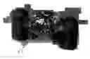
FIG. 1 shows a partial cutaway view of a module having a seat secured between two prongs, according to one preferred embodiment of this invention;
FIG. 2 shows the module shown in FIG. 1, but with a gemstone mounted on the seat of the module;
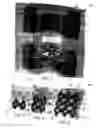
FIG. 3 shows a top view of a building block for a lattice structure, according to one preferred embodiment of this invention;
FIG. 4 shows a top view of a 2×2 lattice structure, according to one preferred embodiment of this invention;
FIG. 5 shows a top view of a 3×3 lattice structure, according to one preferred embodiment of this invention;
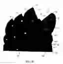
FIG. 6 shows a top view of a 4×4 lattice structure, according to one preferred embodiment of this invention;
FIG. 7 shows a top view of a building block similar to FIG. 3 with mounted gemstones, according to one preferred embodiment of this invention;
FIG. 8 shows a top view of a lattice structure similar to FIG. 4 with mounted gemstones, according to one preferred embodiment of this invention;
FIG. 9 shows a top view of a lattice structure similar to FIG. 5 with mounted gemstones, according to one preferred embodiment of this invention;
FIG. 10 shows a top view of a lattice structure similar to FIG. 6 with mounted gemstones, according to one preferred embodiment of this invention;
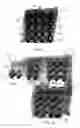
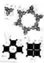
FIG. 11 shows a top view of one configuration of a building block for a lattice structure, according to one preferred embodiment of this invention;
FIG. 12 shows a top view of six of the lattice structure configurations of FIG. 11, connected with respect to each other;
FIG. 13 shows a top view of one configuration of a lattice structure having square or rectangular gemstones, according to one preferred embodiment of this invention;
FIG. 14 shows a top view of one configuration of a lattice structure having square or rectangular gemstones, according to one preferred embodiment of this invention;
FIG. 15 shows a top view of one configuration of a lattice structure, according to another preferred embodiment of this invention;
FIG. 16 shows a top view of the configuration shown in FIG. 15 having mounted gemstones;
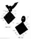
FIG. 17 shows a top view of a lattice structure attached with respect to a ring, according to one preferred embodiment of this invention;
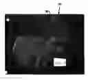
FIG. 18 shows a top view of a lattice structure attached with respect to a pendant, according to one preferred embodiment of this invention;
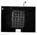
FIG. 19 shows a perspective view of a module with a first gemstone positioned within a first seat of the module and a second gemstone positioned within a second seat of the module, and a shared prong connecting adjacent modules of the lattice structure, according to one preferred embodiment of this invention;
FIG. 20 shows the lattice structure of FIG. 19 with the modules removed, and an edge portion of a first gemstone retained within a first bezel formed in each shared prong and an edge portion of a second gemstone retained within a second bezel formed in each shared prong;
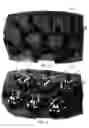
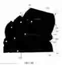
FIG. 21 shows a first side of a lattice structure including a frame, and with a first surface of gemstones mounted within the lattice structure, according to one preferred embodiment of this invention;
FIG. 22 shows an opposing second side of the lattice structure shown in FIG. 21 with a second surface of gemstones mounted within the lattice structure;
FIG. 23 shows the first side of the lattice structure shown in FIG. 21 with the frame removed, and with the first surface of gemstones mounted within the lattice structure;
FIG. 24 shows the opposing second side of the lattice structure shown in FIG. 22 with the framed removed, and with the second surface of gemstones mounted within the lattice structure;
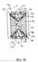
FIG. 25 shows a partial cross-sectional side view of a portion of a lattice structure, according to one preferred embodiment of this invention; and
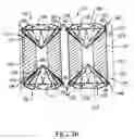
FIG. 26 shows a partial cross-sectional side view of a portion of a lattice structure, according to one preferred embodiment of this invention.
DETAILED DESCRIPTION OF THE INVENTIONFIGS. 1-18 show different perspective views of different embodiments of a mounting for a gemstone 15 particularly to form lattice structures and elements for lattice structures which comprise an article of jewelry or similar object containing multiple gemstones 15, according to this invention.
As used in the specification and claims, an article of jewelry 10 as described and claimed may include, but is not limited to, a ring, a pendant, a bracelet, a pin, a necklace, a collar, earrings, a broach, any combination thereof and/or any other article of jewelry including two or more gemstones known to those having ordinary skill in the art. In addition, the gemstone 15 may comprise a marquis, round, square, pear or any other cut of gemstone known to those having ordinary skill in the art.
As shown in FIG. 1-6, the article 10 may include a seat 21. The seat 21 may comprise a conical taper, such as shown in FIG. 1, a tapered ring, a cylinder, a wire ring or any other suitable structure that engages with the gemstone 15. The gemstone 15 is accordingly positioned on, in or with respect to the seat 21.
FIG. 1 shows a single module 20. As shown in FIG. 1, module 20 comprises two prongs 25 spaced apart from each other. Each prong 25 preferably has bezel 26 within an upper portion of prong 25. The two prongs 25 are preferably positioned one on each side of the gemstone 15. The prongs 25 preferably each include a bezel 26 formed therein so that the gemstone 15 is retained within the bezel 26. Seat 21 and/or bezel 26 can have any suitable shape that accommodates the shape and/or size of gemstone 15. FIG. 1 shows module 20 without a mounted gemstone. FIG. 2 shows module 20 of FIG. 1 but with gemstone 15 mounted within seat 21 and within bezels 26. Each gemstone 15 preferably has at least two prongs 25 for securely mounting or attaching gemstone 15 with respect to module 20. Although not shown in FIGS. 1 and 2, each module 20 may comprise three or more prongs 25, depending upon the particular size and shape of gemstone 15.
As described, the seat 21 and prongs 25 preferably form a single unit within an array or lattice of gemstones 15. As such, additional seats 21, prongs 25 and/or gemstones 15 are added to form a row and/or array of gemstones 15. To facilitate such an arrangement, a shared prong 35 is used between adjacent gemstones 15 to form a “building block” for an array of gemstones 15. The basic element or building block as described is best shown FIG. 3. As shown in FIGS. 3-6, each seat 21 preferably corresponds with two prongs 25 and a shared prong 35. FIGS. 7-10 correspond to lattice structures 10 as shown in FIGS. 3-6, respectively, but FIGS. 7-10 show mounted gemstones 15. With two or more gemstones 15 in the array, such as shown in FIGS. 7-10, the outermost gemstones 15 of each array has an unattached outer edge 18 which aesthetically appears as a floating edge.
Accordingly, an additional gemstone 15 is positioned on an additional seat 21 and two additional prongs 25 are positioned one on each side of the additional gemstone 15, each prong 25 of the two additional prongs 25 having a bezel 26 formed therein so that the additional gemstone 15 is retained within the bezel 26. In addition, the shared prong 35 is positioned between the gemstone 15 and the additional gemstone 15. The shared prong 35 preferably includes a bezel 26 formed on each side of the shared prong 35 to partially engage with a respective inner edge 17 of the gemstone 15 and inner edge 17 of the additional gemstone 15. The article of jewelry 10 thus may include gemstones 15 around a periphery of the article of jewelry 10 have an exposed and unbound outer edge 18. Each exposed and unbound outer edge 18 is thus opposite the shared prong 35 and the respective inner edge 17.
The arrangement may be repeated with further additional seats 21, gemstones 15 and/or shared prongs 35 to create a row of gemstones 15. Multiple rows of gemstones 15 may be connected with respect to each other to form an array or lattice of gemstones that is integrated with the article of jewelry 10.
Such an array of gemstones 15 preferably includes a shared prong 35 positioned between each additional gemstone 15 that is shared between adjacent gemstones 15. Preferably, the article of jewelry is thereby created wherein each gemstone 15 includes an inner edge 17 that is positioned against a common shared prong 35 and along an outer edge or periphery of the article of jewelry 10, each gemstone 15 includes an exposed and/or unbound outer edge 18, i.e., an outer edge 18 not bound or restrained with a prong 25 or shared prong 35. The shared prong 35 preferably includes a pair of bezels 26 formed along each of two opposite sides of the shared prong 35 so that the pair of bezels 26 accommodate inner edges 17 of adjacent gemstones 15.
Such arrays of gemstones 15 may be formed into a ring shape, a lattice, a star or any other suitable shape, configuration or arrangement that facilitates placement on, or creation of, an article of jewelry 10. FIG. 10 shows how lattice structure 10 of this invention can be used to form an overall structure that appears as a surface of gemstones.
FIGS. 3-6 each shows a different configuration of lattice structure 40, according to this invention. FIG. 3 shows module 20 having two prongs 25 and the shared prong 35. FIG. 4 shows a configuration wherein two modules 20 share the common shared prong 35. The outer edges of each seat 21, as shown in FIG. 5, preferably have no corresponding or attached prong 25. Thus, as shown in FIG. 10 for example, the corresponding outer edge portion 18 of gemstone 15 is free, having no corresponding prong 25, and thus aesthetically appears to float with no attached mounting. FIGS. 8-10 show a 2×2 array, a 3×3 array and a 4×4 array, respectively.
According to one preferred embodiment of this invention, seat 21 is mounted between and connects prongs 25 and shared prong 35. Seat 21 can alternatively be integrated with prongs 25. FIG. 15 shows one preferred embodiment where prong 25 is integrated with seat 21 of module 20. FIG. 16 shows modules 20 as shown in FIG. 15, but with gemstones 15 mounted within corresponding modules 20. Outer and/or inner prongs 25, as shown in FIGS. 15 and 16, can be eliminated to provide a free outer edge 18, as discussed in other embodiments of this invention. Seat 21 can also be an individual component secured to prongs 25 in any suitable manner known to those skilled in the art of jewelry design and manufacture.
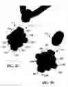
FIG. 11 shows another embodiment of a configuration having an array of three gemstones 15. As shown in FIG. 11, each gemstone 15 is supported by a prong 25 and two shared prongs 35. FIG. 12 shows a configuration having six of the arrays of FIG. 11 attached with respect to each other.
FIGS. 13 and 14 each shows a different configuration of an array of four gemstones 15. As shown in FIG. 13, each gemstone 15 is supported or mounted at two prongs 25 and two shared prongs 35. The array of four gemstones 15 as shown in FIG. 14 provides a relatively small space between adjacent gemstones 15. The configuration shown in FIG. 13 provides negative space 30 between the four gemstones 15.
FIGS. 3-16 are intended to show examples of different configurations of arrays of gemstones 15, formed by lattice structure 10 according to this invention. This invention also contemplates other arrangements that include an array of two or more gemstones 15.
Each array of this invention may include all similarly shaped gemstones 15, or can include differently shaped gemstones 15. Each gemstone 15 can have a shape which is round, square, triangular, baguette, marquis, oval, or any other shape that is a standard or even non-standard shape for a gemstone, such as a diamond. As such, prongs 25, shared prongs 35, bezels 26 and/or seats 21 can be configured in different sizes and shapes to accommodate differently sized and shaped gemstones 15.
Lattice structure 10 of this invention can be used to mount gemstones 15 to form a piece of jewelry that appears to have a flat, concave and/or convex surface of gemstones. FIG. 17 shows a lattice structure 10, having a generally concave surface, attached with respect to a ring mounting. With certain edges unattached to prong 25 or another similar structure, the overall surface formed by gemstones can also appear to be somewhat floating, particularly when viewed from above, such as shown in FIG. 10. Further, FIG. 18 shows a lattice structure as applied to a pendant having a plurality of gemstones 15 arranged in an array.
Prongs 25, bezels 26, seats 21 and/or gemstones 15 can be made of any metal or non-metal material which is suitable for structurally mounting gemstone 15 with respect to module 20.
In one preferred embodiment of this invention, a lattice structure provides multiple sides and/or surfaces for mounting a plurality of gemstones to form an article of jewelry, such as a ring, a pendant, a bracelet, a pin, a necklace, a collar, earrings, a broach, any combination thereof and/or any other article of jewelry including gemstones known to those having ordinary skill in the art. In addition, the gemstones may comprise a marquis, round, square, pear or any other shaped or styled cut of gemstone known to those having ordinary skill in the art. Referring to FIGS. 19-26, a lattice structure 112 provides a first surface of gemstones arranged and mounted to a first side 114 of lattice structure 112 and a second surface of gemstones arranged and mounted to a second, preferably opposing, side 116 of lattice structure 112.
Referring further to FIGS. 25 and 26, lattice structure 112 includes at least one module 120 forming or including a first seat 122 at a first end portion 123 of module 120. A second seat 124 is formed at an opposite second end portion 125 of module 120. Module 120 may have a generally solid cross-section or module 120 may have a generally cylindrical or tubular cross-section, or another structurally suitable non-solid cross-section. Suitable materials for making module 120 include metals, alloys, and/or composite materials, and/or any suitable material known to those skilled in the art. Preferably, but not necessarily, module 120 has a generally cylindrical or tubular outer surface. A first gemstone 130 is positionable within or on first seat 122. In one preferred embodiment of this invention, first gemstone 130 contacts or is seated against a surface 126 formed in or by first seat 122. Preferably, surface 126 forms a tapered or generally conical section that engages a portion of first gemstone 130. For example, at least a portion of a pavilion 131 of first gemstone 130 is positionable and mountable within first seat 122.
A second gemstone 135 is positionable within or on second seat 124. Second gemstone 135 preferably, but not necessarily, has a same or similar shape, size and/or weight to a shape, size and/or weight of first gemstone 130. Second gemstone 135 may have the same or similar color or a different color than first gemstone 130. In one preferred embodiment of this invention, second gemstone 135 contacts or is seated against a surface 128 formed in or by second seat 124. Preferably, surface 128 forms a tapered or generally conical section that engages a portion of second gemstone 135, such as at least a portion of a pavilion 136 of second gemstone 135. With first gemstone 130 mounted within first seat 122 and second gemstone 135 mounted within second seat 124, a crown 132 of first gemstone 130 is positioned generally opposite or in a generally opposing relationship with a crown 137 of second gemstone 135. The term opposing relationship refers to an arrangement wherein crown 132 extends outwardly from first side 114 of lattice structure 112 and crown 137 extends outwardly from second side 116 of lattice structure 112 such that crown 132 and crown 137 face generally opposite directions, such as shown in FIGS. 19-26. In such an arrangement, a plurality of first gemstones 130 each positioned within a corresponding first seat 122 forms a first surface or array of gemstones and a plurality of second gemstones 135 each positioned within a corresponding second seat 124 forms an opposing second surface or array of gemstones.
First seat 122 and/or second seat 124 may be integrated with module 120 or may be formed independently. In one preferred embodiment of this invention, second seat 122 is positioned with respect to first seat 124 in an opposing relationship, such as shown in FIG. 25. With first seat 122 connected or attached to second seat 124 a back surface 127 of first seat 122 contacts a back surface 129 of second seat 124 to form module 120. With back surface 127 contacting back surface 129, first gemstone 130 is configured in an opposing relationship with second gemstone 135.
In one preferred embodiment of this invention, at least one prong 140 is connected with respect to module 120, such as shown in FIG. 25. Each prong 140 forms a first bezel 142 that is positionable with respect to first end portion 123 of module 120. First bezel 142 at least partially engages an edge portion 133 of first gemstone 130 such that edge portion 133 is retainable within first bezel 142. Each prong 140 preferably forms a second bezel 144 positioned with respect to second end portion 125 of module 120. Second bezel 144 at least partially engages an edge portion 138 of second gemstone 135 such that edge portion 138 is retainable within second bezel 144.
In one preferred embodiment of this invention, lattice structure 112 includes a second module 150 positioned with respect to first module 120, as shown for example in FIG. 26. Preferably, but not necessarily, second module 150 is the same or similar to first module 120, having the same dimensions and/or size as first module 120. Alternatively, second module 150 can have different shapes, dimensions and/or sizes than first module 120, such as a different diameter size. Second module 150 forms or includes a first seat 152 at a first end portion 153 of second module 150. An additional first gemstone 130 is positionable within or on first seat 152. In one preferred embodiment of this invention, first gemstone 130 contacts or is seated against a surface 156 formed in or by first seat 152. Preferably, surface 156 forms a tapered or generally conical section that engages a portion of first gemstone 130, such as at least a portion of pavilion 131 of first gemstone 130.
Additionally, second module 150 includes or forms a second seat 154 at a second end portion 155 of second module 150. A second gemstone 135 is positionable within or on second seat 154. In one preferred embodiment of this invention, second gemstone 135 contacts or is seated against a surface 158 formed in or by second seat 152. Preferably, surface 158 forms a tapered or generally conical section that engages a portion of second gemstone 135, such as at least a portion of pavilion 136 of second gemstone 135.
As shown in FIGS. 19, 20 and 26, at least one shared prong 160 connects or attaches first module 120 to second module 150. Each shared prong 160 forms or includes a pair of first bezels 162. Preferably, one first bezel 162 is positioned with respect to each of first end portions 123 and 153 of modules 120 and 150, respectively. An edge portion 133 of first gemstone 130 is retainable within first bezel 162 positioned with respect to first end portion 123 and an edge portion 133 of additional first gemstone 130 is retainable within first bezel 162 positioned with respect to first end portion 153. Each shared prong 160 also forms or includes a pair of second bezels 164 positioned with respect to second end portions 125 and 155 of modules 120 and 150, respectively. An edge portion 138 of second gemstone 135 is retainable within second bezel 164 positioned with respect to second end portion 153 and an edge portion 138 of additional second gemstone 135 is retainable within second bezel 164 positioned with respect to second end portion 155.
In certain preferred embodiments of this invention, shared prong 160 may have any suitable number of first bezels 162 and/or second bezels 164. For example, shared prong 160 may include a plurality of first bezels 162 each accommodating an edge portion of one first gemstone 130 of adjacent first gemstones 130 and a plurality of second bezels 164 each accommodating an edge portion of one second gemstone 135 of adjacent second gemstones 135. Further, any suitable combination of prongs 140 and/or shared prongs 160 can be used to make lattice structure 112 in any suitable size and/or shape.
An article of jewelry 110, such as a pendent, preferably includes lattice structure 112 having any suitable number of modules 120 and/or 150 connected together using any suitable combination of prongs 140 and/or shared prongs 160. As shown in FIGS. 21-24, with a first gemstone 130 mounted within or on each first seat 122 and a second gemstone 135 mounted within or on each second seat 124, lattice structure 112 forms article of jewelry 110 having two opposing surfaces of gemstones. In one preferred embodiment of this invention, a frame 170 is positionable about an outer edge or boundary 118 of lattice structure 112, such as shown in FIGS. 21 and 22.
For example, lattice structure 112 may include an array of first seats 122 and an array of corresponding second seats 124. An array of first gemstones 130 are positioned within respective first seats 122 and an array of second gemstones 135 are positioned within respective second seats 124. A shared prong 160 is positioned between adjacent first gemstones 130 and positioned between adjacent second gemstones 135 so that each first gemstone 130 along outer edge 118 of lattice structure 112 includes an exposed edge portion 134 and each second gemstone 135 along outer edge 118 includes an exposed edge portion 139, as shown in FIGS. 23 and 24 for example.
The invention illustratively disclosed herein suitably may be practiced in the absence of any element, part, step, component, or ingredient which is not specifically disclosed herein.
While in the foregoing detailed description this invention has been described in relation to certain preferred embodiments thereof, and many details have been set forth for purposes of illustration, it will be apparent to those skilled in the art that the invention is susceptible to additional embodiments and that certain of the details described herein can be varied considerably without departing from the basic principles of the invention.
Claims
1. A lattice structure comprising:
a module forming a first seat at a first end portion of the module and forming a second seat at an opposite second end portion of the module, a first gemstone positionable within the first seat and a second gemstone positionable within the second seat; and
at least one prong connected with respect to the module, each said prong forming a first bezel positioned at the first end portion, an edge portion of the first gemstone retainable within the first bezel, each said prong forming a second bezel positioned at the second end portion, and an edge portion of the second gemstone retainable within the second bezel.
2. The lattice structure of claim 1 further comprising:
a second module forming a first seat at a first end portion of the second module and forming a second seat at a second end portion of the second module, an additional first gemstone positionable within the first seat and an additional second gemstone positionable within the second seat; and
a shared prong connecting the first module to the second module, the shared prong forming a first bezel positioned at the first end portion of the first module, an edge portion of the first gemstone retainable within the first bezel, the shared prong forming a second bezel positioned at the second end portion of the first module, and an edge portion of the second gemstone is retainable within the second bezel.
3. The lattice structure of claim 2 wherein the shared prong forms an additional first bezel positioned at the first end portion of the second module, an edge portion of the additional first gemstone retainable within the additional first bezel, the shared prong forms an additional second bezel positioned at the second end portion of the second module, and an edge portion of the additional second gemstone is retainable within the additional second bezel.
4. The lattice structure of claim 2 wherein the shared prong includes a plurality of first bezels, one first bezel of the first bezels accommodating an edge portion of the first gemstone and another first bezel of the first bezels accommodating an edge portion of the additional first gemstone.
5. The lattice structure of claim 4 wherein the shared prong includes a plurality of second bezels, one second bezel of the second bezels accommodating an edge portion of the second gemstone and another second bezel of the second bezels accommodating an edge portion of the additional second gemstone.
6. The lattice structure of claim 1 further comprising a frame positioned about an outer edge of the lattice structure.
7. The lattice structure of claim 1 wherein a crown of the first gemstone is in an opposing relationship with a crown of the second gemstone.
8. The lattice structure of claim 1 wherein at least a portion of a pavilion of the first gemstone is seated within the first seat and at least a portion of a pavilion of the second gemstone is seated within the second seat.
9. The lattice structure of claim 1 wherein a surface of the first seat forms a first generally conical section that engages a portion of the first gemstone and a surface of the second seat forms a second generally conical section that engages a portion of the second gemstone.
10. The lattice structure of claim 1 further comprising:
an array of additional first seats and an array of corresponding additional second seats;
an array of additional first gemstones positioned within the respective first seats and an array of additional second gemstones positioned within the respective second seats; and
a shared prong positioned between adjacent additional first gemstones of the array of additional first gemstones and positioned between adjacent additional second gemstones of the array of additional second gemstones so that each first gemstone along an outer edge of the lattice structure includes an exposed edge portion and each second gemstone along an outer edge of the lattice structure includes an exposed edge portion.
11. A lattice structure comprising:
a first module forming a first seat at a first end portion of the first module and a second seat at a second end portion of the first module, a first gemstone positionable within the first seat and a second gemstone positionable within the second seat;
a second module forming a first seat at a first end portion of the second module and a second seat at a second end portion of the second module, an additional first gemstone positionable within the first seat of the second module and an additional second gemstone positionable within the second seat of the second module; and
at least one shared prong connecting the first module to the second module, each shared prong of the at least one shared prong forming a pair of first bezels positioned at a distance from the first end portions of the first module and the second module, an edge portion of the first gemstone retained within one first bezel of the pair of first bezels and an edge portion of the additional first gemstone retained within another first bezel of the pair of first bezels, each shared prong of the at least one shared prong forming a pair of second bezels positioned with respect to the second end portions of the first module and the second module, and an edge portion of the second gemstone retained within one second bezel of the pair of second bezels and an edge portion of the additional second gemstone retained within another second bezel of the pair of second bezels.
12. The lattice structure of claim 11 further comprising:
at least one prong connected with respect to the first module, each said prong forming a first bezel positioned at the first end portion of the first module, an edge portion of the first gemstone retained within the first bezel, each said prong forming a second bezel positioned at the second end portion of the first module, and an edge portion of the second gemstone retained within the second bezel.
13. The lattice structure of claim 11 further comprising a frame positioned about an outer edge of the lattice structure.
14. The lattice structure of claim 11 wherein a crown of each first gemstone of a plurality of first gemstones is in an opposing relationship with a crown of a corresponding second gemstone of a plurality of second gemstones.
15. The lattice structure of claim 11 wherein at least a portion of a pavilion of each first gemstone is seated within each corresponding first seat and at least a portion of a pavilion of each second gemstone is seated within each corresponding second seat.
16. The lattice structure of claim 11 wherein each first seat forms a first generally conical section that engages a portion of the corresponding first gemstone and each second seat forms a second generally conical section that engages a portion of the corresponding second gemstone.
17. A lattice structure comprising:
a first seat having a first surface;
a first gemstone seated on the first surface;
a second seat positioned at a distance from the first seat in an opposing relationship, and forming a second surface;
a second gemstone seated on the second surface; and
at least one prong each having a first bezel, the first gemstone retained within the first bezel, each prong having a second bezel, and the second gemstone retained within the second bezel.
18. The lattice structure of claim 17 wherein a back surface of the first seat contacts a back surface of the second seat.
19. The lattice structure of claim 17 further comprising:
an additional first seat positioned at a distance from the first seat;
an additional first gemstone positioned on the additional first seat;
an additional second seat positioned at a distance from the additional first seat in an opposing relationship, and at a distance from the second seat; and
a shared prong positioned between the first gemstone and the additional first gemstone and between the second gemstone and the additional second gemstone, the shared prong including two first bezels, one first bezel of the two first bezels partially engaging with an edge portion of the first gemstone and another first bezel of the two first bezels partially engaging an edge portion of the additional first gemstone, the shared prong including two second bezels, one second bezel of the two second bezels partially engaging with an edge portion of the second gemstone and another second bezel of the two second bezels partially engaging an edge portion of the additional second gemstone.
Images & Drawings included:
Sources:
- United States Patent and Trademark Office - verify current appl. status at the USPTO↗
Similar patent applications:
- » 20050210919
Lattice structure forming a surface of gemstones
Recent applications in this class:
- » 20240335013 2024-10-10
SUPPORT FOR A TIMEPIECE OR ITEM OF JEWELLERY COMPRISING THE SUPPORT AND A DECORATIVE INSERT - » 20240225214 2024-07-11
METHOD OF GEM COMPOSITION FOR THE MANUFACTURE OF JEWELLERY (CRYSTAL IN CRYSTAL) - » 20240130490 2024-04-25
METHOD OF GEM COMPOSITION FOR THE MANUFACTURE OF JEWELLERY (CRYSTAL IN CRYSTAL) - » 20230337790 2023-10-26
JEWEL SUPPORT BASE AND ORNAMENT - » 20230083471 2023-03-16
GOLD STONE JEWELRY PRODUCTS AND METHODS - » 20220408889 2022-12-29
Basket-Type Gemstone Setting - » 20220361635 2022-11-17
Jewelry item having settings for securing a center stone and side stones - » 20210227940 2021-07-29
Accessories for which small gemstones can be utilized and method for manufacturing same - » 20210204661 2021-07-08
DECORATIVE COMPONENT AND ARTICLE INCLUDING THE SAME - » 20210169185 2021-06-10
Decorative element made by a setting technique