Rotor blade with an electrical field
US20050201865A1
2005-09-15
11/085,630
2005-03-21
✅ Patent granted
US 7,311,490 B2
2007-12-25
-
-
Edward K. Look | Dwayne J White
2026-03-02
Abstract:
The invention concerns a rotor blade, in particular a rotor blade of a wind power installation. The object of the present invention is to provide measures for still further improving the CR-value and also the level of acoustic power of rotor blades of wind power installations. A rotor blade for a wind power installation comprising a pressure side and a suction side, wherein a substantially constant, area-covering electrostatic field is provided on the suction side.
Interested in similar patents?
Get notified when new applications in this technology area are published.
Classification:
F03D1/0641 » CPC main
Wind motors with rotation axis substantially parallel to the air flow entering the rotor ; Rotors characterised by their form of the blades of the section profile of the blades
F03D9/25 » CPC further
Adaptations of wind motors for special use; Combinations of wind motors with apparatus driven thereby; Wind motors specially adapted for installation in particular locations; Wind motors characterised by the driven apparatus the apparatus being an electrical generator
F03D80/00 » CPC further
Details, components or accessories not provided for in groups -
B64C2230/12 » CPC further
Boundary layer controls by using electromagnetic tiles, fluid ionizers, static charges or plasma
F05B2220/7068 » CPC further
Application in combination with an electrical generator equipped with permanent magnets
F05B2240/30 » CPC further
Components; Rotors Characteristics of rotor blades, i.e. of any element transforming dynamic fluid energy to or from rotational energy and being attached to a rotor
Y02E10/72 » CPC further
Energy generation through renewable energy sources; Wind energy Wind turbines with rotation axis in wind direction
Y02E10/72 » CPC further
Energy generation through renewable energy sources; Wind energy Wind turbines with rotation axis in wind direction
Y02T50/10 » CPC further
Aeronautics or air transport Drag reduction
Y02T50/10 » CPC further
Aeronautics or air transport Drag reduction
F03D7/02 IPC
Controlling wind motors the wind motors having rotation axis substantially parallel to the air flow entering the rotor
Description
BACKGROUND OF THE INVENTION1. Field of the Invention
The invention concerns a rotor blade, in particular a rotor blade of a wind power installation.
2. Description of the Related Art
Rotor blades for wind turbines are known in many different forms. The goal is usually to design the rotor blades of a wind power installation in such a way that in operation they have a level of acoustic power which is as low as possible and in addition present such a low air resistance value that a very small amount of losses of wind energy is caused by the rotor blades.
Usually the approaches adopted for reducing the level of acoustic power and also for reducing the CR-value (coefficient of resistance) involve changing or improving an external design which is suitably adapted for the rotor blade.
BRIEF SUMMARY OF THE INVENTIONThe object of the present invention is to provide measures for still further improving the CR-value and also the level of acoustic power of rotor blades of wind power installations.
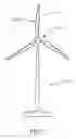
BRIEF DESCRIPTION OF THE SEVERAL VIEWS OF THE DRAWING(S)FIG. 1 shows a front view of a wind power installation including rotor blades according to the invention.
FIGS. 2A, 2B show plan views of the suction side of embodiments of a rotor blade according to the invention.
FIGS. 3A, 3B, 3C show simplified cross-sectional views of embodiments of a rotor blade according to the invention taken along line A-A of FIG. 2A.
FIG. 4 shows the characteristics of the CR-value in dependence on the voltage of the electrical field.
FIG. 5 shows the characteristics of the coefficient of power (Cp) in dependence on the voltage of the electrical field.
DETAILED DESCRIPTION OF THE INVENTIONThe invention is attained by a rotor blade having the features of claim 1. Advantageous developments are set forth in the appendant claims.
FIG. 1 shows a front view of a wind power installation 10 including rotor blades 14 according to the invention. The wind power installation 10 has a rotor 12 which carries the rotor blades 14. The present invention provides that an electrical field 16 is produced at least on the suction side of the rotor blade 14. That electrical field 16 is preferably an electrostatic field with a voltage of for example about −4 kV at the top side of the rotor blade 14.
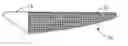
FIG. 2A is a plan view of the suction side of one embodiment of a rotor blade 14 according to the invention. The electrical field 16 is provided in the region from the leading edge of the rotor blade 14 as far as the trailing edge at at least 30% of the rotor blade 14 in the rotor blade tip region, that is to say the region which is furthest away from the rotor blade root of the rotor blade 14. FIG. 2B shows another embodiment of a rotor blade 14 in which the electrical field 16 is provided to cover lager region of the rotor blade 14.
Preferably a network-like conductor structure 18 is provided on the suction side of the rotor blade 14 to produce the electrical field 16. The network-like conductor structure 18 can comprise a conductor matrix (for example of copper), wherein a plurality of conductors are disposed in mutually juxtaposed transverse relationship with each other in a mesh configuration and the spacing parallel to each other is in the region of between about 1 and 10 mm, preferably in the region of 4 mm or less.
It was now surprisingly found that the application of an electrical field 16 of a value of between about −2 and −10 kV, preferably about −4 kV, causes the power value of the rotor blade 14 to rise, to a factor of between about 10 and 15%, preferably 12%. At the same time the level of acoustic power of the rotor blade 14 according to the invention is reduced by about 1 dB or less.
To maintain the electrical field 16 on the suction side an electrical power with rotor blades 14 of a length of about 20 m of about 5 kV per rotor blade has to be provided and with a rotor blade length of about 32 m the electrical power must be about 15 kV per rotor blade.
The graphs in FIG. 4 and FIG. 5 show the characteristics of the CR-value in dependence on the voltage of the electrical field and the characteristics of the coefficient of power (Cp) in dependence on the voltage of the electrical field.
| CR | Voltage (V) | |
| 100 | 0 | |
| 90 | 1.6 | |
| 80 | 3.9 | |
| 70 | 5.3 | |
| 60 | 6.6 | |
| 50 | 7.5 | |
| 40 | 8.2 | |
| 30 | 8.8 | |
| 20 | 9.2 | |
| 10 | 9.3 | |
| 0 | 9.4 | |
It can be seen in that respect that the coefficient of power CR reaches power values at about 4 kV and 3.9 kV respectively as a maximum and falls again at voltage values of less than 3.9 and 4 kV respectively.
FIG. 3A shows a simplified cross-sectional view of an embodiment of a rotor blade 14 according to the invention taken along line A-A of FIG. 2A. In this embodiment, the network-like conductor structure 18 is only on the suction side of the rotor blade 14. The size and shape of the electrical field will be determined by the value of the voltage placed on the conductor structure 18, as well as the shape of the blade and whether the blade has internal or external metal components, such as a front metal surface.
A layer that forms the outer layer of the blade which contacts the wind can be on top of the network conductor 18 in one embodiment. This layer can be a fiberglass, protective coating, plastic, laminate sheeting, polyvinyl sheeting that covers the network-like conductor structure 18 in order to give preferable properties to the surface of the rotor blade 14 and to protect the network-like conductor structure 18.
In another embodiment, an electrical field 16b for example with a voltage in the same direction or in opposite relationship can be applied at the pressure side of the rotor blade 14 as shown in FIG. 3B. In the embodiment in FIG. 3B, a network-like conductor structure 18b is installed on the pressure side of the rotor blade 14 as well as a network-like conductor structure 18a on the suction side of the rotor blade 14.
In yet another embodiment shown in FIG. 3C, a network-like conductor structure 18c is installed inside the rotor blade 14. According to this embodiment, the installation of the network-like conductor structure 18c does not affect the surface properties of the rotor blade 14.
The application of the electrical field 16 at the rotor blade 14 can comprise a galvanic connection between the rotor blade 14 and a voltage or charge supply device within the wind power installation 10. Preferably there are provided means for separating that galvanic connection, which means can be in the form of switches which already permit galvanic separation at the rotor blade 14, at the rotor blade root or the hub or within the wind power installation 10. It is also possible to provide more than one switch within the galvanic connection.
The galvanic separation between the voltage supply means and the rotor blade 14 is preferably interrupted when a thunderstorm is approaching. In that respect it is also possible for the interruption to take place automatically when a corresponding thunderstorm situation is detected. That can be measured by a sensor that detects, for example severe power fluctuations because severe power fluctuations of the wind power installation 10 or severe fluctuations in the wind are an indication of gusts which usually precede a thunderstorm. It is however also possible to detect an approaching thunderstorm by measurement of the electrical voltage within the air. Usually that voltage rises or falls when a thunderstorm approaches and can therefore be taken as a relatively reliable indication of such a thunderstorm.
Shutting down the field therefore by galvanic separation between the rotor blade 14 and the voltage supply means serves for protecting the entire wind power installation 10, in particular the rotor blades 14. It will be appreciated that it is also possible to control a corresponding interruption in the voltage supply means with other means which are already known and with which the approach of a thunderstorm can be detected.
From the foregoing it will be appreciated that, although specific embodiments of the invention have been described herein for purposes of illustration, various modifications may be made without deviating from the spirit and scope of the invention. Accordingly, the invention is not limited except as by the appended claims.
Claims
1. A rotor blade for a wind power installation comprising a pressure side and a suction side, wherein a substantially constant, area-covering electrostatic field is provided on the suction side.
2. The rotor blade according to claim 1, characterized in that the electrical field is produced in the region between the rotor blade leading edge and the trailing edge of the rotor blade on the suction side of the rotor blade.
3. The rotor blade according to claim 1, characterized in that a network-like conductor structure on the suction side of the rotor blade forms a matrix, wherein the spacing between adjacent conductors is in the region of between 2 and 10 mm, preferably 4 mm or less.
4. The rotor blade according to claim 1, characterized in that the voltage applied to the network-like conductor structure is in the range of between −2 and −6 kV, preferably about −4 kV or less.
5. A wind power installation comprising at least one rotor blade according to claim 1.
6. The wind power installation according to claim 6, characterized in that the desired dc voltage is applied to the network-like conductor structure of the rotor blade by means of a DC voltage supply means.
7. A rotor blade for a wind power installation comprising:
a first side having a surface shaped to be a pressure side and receive the wind on the surface thereof;
a second side having a surface shaped to be a suction side, behind the first side; and
a grid conductor structure positioned adjacent to the surface of the second side of the blade.
8. The rotor blade according to claim 7, wherein the grid conductor structure is located in the tip region of the rotor blade.
9. The rotor blade according to claim 8, wherein the grid conductor structure covers at least 30% of the rotor blade.
10. The rotor blade according to claim 8, wherein the grid conductor provides a electronic field covering at least 30% of the rotor blade.
11. The rotor blade according to claim 7, further comprising:
a grid conductor structure located on the pressure side of the rotor blade.
12. The rotor blade according to claim 7, further comprising:
a coating layer over the grid conductor structure.
13. The rotor blade according to claim 7, wherein the grid conductor structure is located inside the rotor blade, adjacent to the surface.
Images & Drawings included:


Sources:
- United States Patent and Trademark Office - verify current appl. status at the USPTO↗
Recent applications in this class:
- » 20240167450 2024-05-23
A WIND TURBINE BLADE - » 20240035436 2024-02-01
Open and closed cycle lift force turbines - » 20230366370 2023-11-16
WIND TURBINE ROTOR BLADE AND WIND TURBINE - » 20230265826 2023-08-24
ROTOR BLADE OF A WIND POWER INSTALLATION - » 20230235723 2023-07-27
Wind turbine - » 20230160363 2023-05-25
Rotor blade for a wind turbine and wind turbine - » 20220349376 2022-11-03
Wind turbine blade assembly and method for producing a wind turbine blade - » 20220325691 2022-10-13
Wind turbine blade provided with surface mounted device - » 20220307462 2022-09-29
Wind Turbine Blades and Wind Turbine Systems That Include a Co-flow Jet - » 20220235735 2022-07-28
Rotor blade and wind turbine