Hunting aid
US20050211503A1
2005-09-29
10/983,827
2004-11-08
Abstract:
A hunting aid including a removably attachable bar having a securing device and a support for use in various hunting situations. The support semi-permanently attaches to a tree thereby allowing a hunter to removably attach the bar to the support via the securing device. A hunter may use the device as a confidence booster when using a conventional tree stand. Preferred supports include baseplates having engagement regions and slots that receive straps secured about a tree. Preferred bars include a circular hoop having a securing device formed of walls defining a slot. The securing device welds to the hoop. During use, the engagement region of the baseplate fits in the slot from above or below and fills the volume thereof. A fastener may optionally tighten against the engagement region. The hunting aid also includes an optional drape for providing concealment/camouflage to the hunter hunting with or without the tree stand.
Inventors:
- Adrian Evans 1 🇺🇸 Sandy Hook, KY, United States
- Lafayette Boggs 1 🇺🇸 Sandy Hook, KY, United States
Interested in similar patents?
Get notified when new applications in this technology area are published.
Classification:
A01M31/025 » CPC main
Hunting appliances; Shooting stands Hunting blinds, i.e. camouflage
Description
This application claims the benefit of U.S. Provisional Patent Application Ser. No. 60/537,710, filed Jan. 20, 2004.
TECHNICAL FIELDThe present invention relates generally to a hunting aid and, more specifically to a device that removably attaches to a tree for providing a hunter with confidence when using a conventional tree stand. In other aspects, the device also functions to provide a hunter concealment/camouflage in various hunting situations.
BACKGROUND OF THE INVENTIONHunting has always played an important role in civilization. As a necessity for collection of food or as a recreational activity, many individuals participate in hunting. Over time, many styles of hunting have developed. For instance, some hunters utilize a bow and arrow for catching game, while others use high-powered rifles with optical scopes. Regardless of the style of hunting, some of the most popular hunted game include whitetail deer and wild turkey.
When hunting deer, hunters often find that they gain an advantage by positioning themselves in an elevated location. This position gives the hunter a better vantage point for observing the deer and it provides greater concealment from visual and scent recognition by the deer.
To meet the demands of this style of hunting, manufacturers offer portable platforms, generally known as tree stands, that the hunter may attach in an elevated position on a tree. Generally, the hunter climbs up the tree and attaches the platform via various mechanisms well known in the art. Once attached, the hunter climbs atop the tree stand to wait for deer or other game to pass by.
In addition to the platform, manufactures often supply leashes with the tree stand. The leash functions as a safety device should the hunter fall off the tree stand platform. One end of the leash attaches to the tree and the other end attaches directly or indirectly to the hunter. Therefore, the leash essentially secures the hunter to the tree.
To facilitate portability and ease of installation of the tree stand, the platform is often very small. Hunters often find movement, such as when positioning for a shot, on the tree stand difficult and somewhat awkward. Therefore, many hunters desire an additional barrier or railing that would work in conjunction with the traditional tree stand and leash system, thereby providing additional support for the hunter. To meet this demand, some manufacturers have developed a hunting aid that boosts the hunters confidence when moving around the tree stand. The hunting aid often consists of a fixedly attached device. However, these devices are prevented from easy portability from one hunting site to another. Moreover, the fixed nature of the hunting aid makes it difficult for the hunter to climb onto and off of the tree stand. Also, due to the limited space on the platform, hunters often find it difficult to position the hunting aid.
Additionally, when hunting on a tree stand or on the ground, many hunters extensively use camouflage material to help conceal their position from the hunted game. From camouflaged clothing to camouflaged rifles, the hunter desires concealment from the acute senses of their prey. To provide further camouflage coverage, some manufacturers offer portable shelters or blinds that a hunter may utilize for assisting in visual and scent containment. Unfortunately, many of these blinds require elaborate frames that are expensive to produce and cumbersome to transport. Moreover, many of these blinds are not designed to be used with conventional tree stands.
Accordingly, the need exists for a hunting aid that provides a barrier or railing for use with a conventional tree stand that enables portability of the hunting aid from one site to another. Moreover, the need exists for a hunting aid that easily installs while a hunter positions themselves on the precarious tree stand. Furthermore, the need exists for a hunting aid that provides concealment features for use in various hunting situations.
SUMMARY OF THE INVENTIONIn accordance with one aspect of the present invention as described herein, a hunting aid for use with a tree is disclosed.
In one embodiment, the hunting aid functions as a railing or barrier for providing confidence to a hunter using a conventional tree stand system. The hunting aid may comprise a bar, such as a hoop, and a support, such as a baseplate. The baseplate semi-permanently secures to a tree via fasteners or a strap. To use the hunting aid in this configuration, the hunter takes the hoop and climbs on top of a previously positioned tree stand. Next, the hunter attaches the hoop to the support via a securing device positioned on the hoop. The securing device may include at least one set screw or other fastener for removably attaching the hoop to the baseplate.
The hoop may also include a padded region for providing cushioning to a hunter leaning or resting against the hoop. The hoop or padded region may also function as a gunrest when sighting or shooting prey. Additionally, the hoop may include a cover for protecting the padded region and adding concealment to the hunting aid. To provide additional concealment to the hunter, the hoop may include a drape attached to the hunting aid.
The following drawings pertain to one possible embodiment of this invention, and are merely designed to illustrate one of the modes best suited to carry out the invention. As it will be realized, the invention is capable of other different embodiments, and its several details are capable of modification in various, obvious aspects all without departing from the invention. Accordingly, the drawings and descriptions will be regarded as illustrative in nature and not as restrictive.
BRIEF DESCRIPTION OF THE DRAWINGSThe accompanying drawings incorporated in and forming a part of the specification, illustrate several aspects of the present invention, and together with the description serve to explain the principles of the invention. In the drawings:
FIG. 1a is a representative diagram showing use of a conventional tree stand hunting system as known in the art;
FIG. 1b is a representative diagram showing a hunting aid in use with the conventional tree stand hunting system forming one possible embodiment of the present invention;
FIG. 2a is an exploded perspective view of one embodiment of attachment of a support of the present invention;
FIG. 2b is an exploded view of one embodiment of the connection of the securing device to the support including a locking device;
FIGS. 2c-2f are side views of the tree showing various embodiments of attachment of the support;
FIGS. 3a and 3b are detailed views of various embodiments of attachment of a strap to the tree;
FIGS. 4a and 4b are detailed and sectional views of various embodiments of supports;
FIG. 5a is a top view of the bar including a securing device forming one possible embodiment of the present invention;
FIGS. 5b-5d are exploded views of various embodiments of the connection of the securing device to the support;
FIG. 6 is a detailed cutaway of one embodiment of the bar of FIG. 5a showing a padded region and cover; and
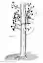
FIG. 7 is a representative diagram of the hunting aid used on the ground without the tree stand forming one possible embodiment of the present invention.
DETAILED DESCRIPTION OF THE INVENTIONReference is now made to FIG. 1a showing a conventional tree stand hunting system 10 as previously known in the art. As shown, the system 10 comprises a platform 12 attached to a tree T and a leash 14 attached from the tree T to a hunter H. FIG. 1b illustrates the hunting aid 16 forming one aspect of the present invention. As noted above, one of the features of the hunting aid 16 is its ability to function as a railing or barrier for providing a hunter H greater confidence when in an elevated position in a conventional tree stand. In one embodiment, this is accomplished by semi-permanently securing a support 18 to a tree T and removably attaching a bar 20 to the support 18.
In one embodiment, shown in FIG. 2a, the support 18 comprises a generally rectangular baseplate 22. The baseplate 22 includes an engagement region 24 that engages a securing device 26 of the bar 20, discussed later in further detail. As illustrated in FIG. 2a, the baseplate 22 includes a top region 22a and a bottom region 22b. In one embodiment, shown in FIG. 2a, the bottom region 22b includes the engagement region 24. Alternatively, the top region 22a may include the engagement region 24 (see FIG. 2d). Thus, the baseplate 22 and engagement region 24 may have any orientation that permits attachment of the bar 20. In one embodiment, shown in FIG. 2a, a first and second ledge 24a, 24b define the engagement region 24. As discussed later, this configuration of the engagement region 24 promotes easy attachment and removal of the bar 20.
The baseplate 22 also includes a plurality of apertures 28 and extending arms 30 for attaching the baseplate 22 to the tree T. In one embodiment, shown in FIG. 2a, the extending arms 30 each comprise a first and second member 30a, 30b outwardly projecting from the base plate, essentially forming a “v” shape. In this configuration, the extending arms 30 may function as barbs for engaging the tree T. In order to avoid interfering with the attachment of the bar 20, the extending arms 30 may have lengths running from the top region 22a to the first and second ledge 24a, 24b of the engagement region 24. As shown in FIG. 2a, the evenly spaced apertures 28 may receive fasteners, such as screws 32, for securing the baseplate 22. In use, the hunter H locates the baseplate 22 in the desired position on the tree. Next, he inserts the screws 32 through the apertures 28 of the baseplate 22 and into the tree, thereby attaching the baseplate 22 to the tree T. As previously discussed, in addition to the screws 32, the extending arms 30 engage the surface of the tree T and help prevent rotation of the attached baseplate 22. Thus, the baseplate 22 remains semi-permanently attached to the tree T.
In another embodiment, shown in FIG. 2b, in addition to the plurality of apertures 28, discussed above, the baseplate 22 may also include a first securing aperture 29a adapted to receive a locking device, such as a pin 31, discussed later in further detail. Alternatively or in addition to the configuration discussed above, the extending arms 30 of the baseplate 22 may include a plurality of pegs 33 outwardly projecting from the baseplate 22 (see FIGS. 2b and 2f). In one embodiment, the baseplate 22 includes four pegs evenly arranged. The pegs 33 assist in offsetting and securing the baseplate 22 to the tree T. The pegs 33 may comprise substantially cylindrical dowels that attach substantially perpendicular to a surface of the baseplate 22. The pegs 33 may attach to the baseplate via welding, mechanical fasteners, or otherwise. In one embodiment, the pegs 33 insert through apertures 28 of the baseplate 22, extend through the entire width of the baseplate W, and become welded in place. The pegs 33 may also include points or barbs (not shown) for assisting in attachment of the baseplate to the tree.
In addition to attachment via fasteners or pegs, the baseplate 22 may attach to the tree via a strap 34. As shown in FIGS. 2c and 2d, the strap 34 may engage a slot 36 located in the baseplate 22. The slot may be positioned and sized on the baseplate to receive the strap 34. The manufacturer may fabricate the baseplate 22 with the strap fixedly attached or the baseplate may include a removable strap such that the hunter may attach or remove the strap, as desired. The strap may attach to the tree via a hook 38 and loop 38a assembly (shown in FIG. 3a), a ratchet assembly (shown in FIG. 3b), or otherwise. In one embodiment, shown in FIG. 2f, instead of or in addition to the strap 34 engaging a slot 36 located in the baseplate 22, the hook 38 of the strap 34 may associate with an aperture 27 of the baseplate. In this configuration, the hunter H places the strap around the tree T and associates the hook 38 with one of the apertures 27 of the baseplate 22 for attachment of the baseplate to the tree T. Alternatively, the strap 34 may include a plurality of hooks 38, such that the hunter H may attach one of the hooks to an aperture 27 of the baseplate 22, place the strap around the tree T, and attach another hook to another aperture of the baseplate. In these configurations, the hunter H may make adjustments to the length of the strap 34 for use with various trees having differing dimensions. The strap 34 may comprise nylon or other material that provides secure attachment of the baseplate 22 to the tree T. Additionally, as representatively shown in FIGS. 2c-2f, a hunter may use any combination of mechanical fasteners and/or strap 34 for semi-permanently attaching the baseplate 22 to the tree T.
In addition to the generally rectangular baseplate shown, the support 18 may take the form of a plate 23 having apertures 28 and a semi-circular engagement region 24 (FIG. 4a). Similar to attachment of the base plate 22, fasteners, such as screws 32 may engage the apertures 28 for attachment of the plate 23 to the tree. As shown in cross-section in FIG. 4a, the engagement region 24 lies in an offset plane parallel to the plate 23. This arrangement facilitates easy attachment and removal of the bar 20 by minimizing interference of the bar 20 with the tree T. The support may also comprise a hook 25 (FIG. 4b) having an aperture 28 for attachment to the tree T, as previously described. As shown in cross-section, the hook 25 may essentially form a “J” shape with an offset engagement region 24. Therefore, the support 18 may take any form, shape, or configuration and attach to the tree T in any manner. The support 18 may also include a threaded region or integrated fasteners (not shown), thereby obviating the need for screws 32 or straps 34. Thus, the support 18 may be adapted to work with many types/sizes of trees and various hunting situations.
With reference to FIG. 5a, the bar 20 in the illustrated embodiment comprises a generally circular hoop 42, which functions as a rail or barrier for boosting the confidence of a hunter positioned on a conventional tree stand. The hoop 42 may comprise one piece of material or multiple pieces joined together and may be formed of any material, but would preferably be metallic tubing, such as a ½″ diameter aluminum, steel or iron tube. The hoop 42 may be formed in any shape or size, however, in one embodiment, the hoop has a diameter D of approximately 2-3 feet.
As shown in FIG. 6, the hoop 42 may include a padded region 44a and a cover 44b. The padded region 44a functions to provide cushioning for a hunter that may be leaning or resting against the hoop 42. The hoop or padded region may also function as a gunrest when the hunter is sighting or shooting prey. The padded region 44a may comprise any material, but preferably a polymer material, such as a polyvinyl chloride (PVC) foam, that fits over the hoop 42. The cover 44b may comprise a weather resistant fabric that fits over the padded region 44a. As shown, the cover 44b may comprise an elongated tube that slides over the hoop 42 and/or the padded region 44a or it may affix to the padded region 44a via hook and loop fasteners, or otherwise. The cover 44b may include a camouflage pattern for assisting in concealing the hunting aid 16. Alternatively, the padded region 44a may be printed or formed with a desired pattern, such as a camouflage pattern, thereby eliminating the need for the cover 44b.
In addition to the cover 44b for the padding 18a, the hoop 42 may include a drape 47. As shown in FIG. 7, the drape 47 may attach to the hoop 42 to provide further concealment of the hunter. As discussed above regarding the cover 44b, the drape 47 may also comprise a camouflage pattern that helps hide the hunter from detection by the hunted game. The drape may attach to the hoop 42 via hook and loop fasteners, stitching, adhesives, or otherwise. The configuration illustrated in FIG. 7 shows the hunting aid 16 positioned in a ground hunting situation, such as used when hunting turkeys. However, the drape may also be used when hunting from the elevated tree stand, thereby providing greater scent and visual concealment of the hunter. Additionally, as shown in FIGS. 5a, 5b and 2b, the hoop 42 also includes a securing device 26 for attachment of the hoop 42 to the support 18. In one embodiment, the securing device 26 includes an elongated rectangular block 46 having a front wall 46a, a back wall 46b, and side walls 46c, 46d. The configuration of walls shown defines an aperture or slot 49 having a volume for receiving a portion of the support 18. In one embodiment, as shown in FIG. 5b, the slot 49 of the securing device 26 associates with the engagement region 24 of the support 18 such that the first ledge 24a contacts the side wall 46c, the second ledge 24b contacts the side wall 46d, and the engagement region 24 substantially fills the volume of the slot. Thus, the size and configuration of the slot 49 may correspond to the size and configuration of the engagement region 24 of the support 18. Alternatively, the engagement region 24 of the support 18 may only partially fill the volume of the slot 49 or it may extend beyond the slot 49, thereby exceeding the volume. In FIG. 2b, the engagement region 24 corresponds to the upper portion 37 of support 18 and has a size and shape slightly less in volume than the void 49. During use, the engagement region 37 fills the entirety of the void 49 and upper surface 39 contacts the surface 51 of the rectangular block.
The rectangular block 46 may act as an intervening joint disrupting the continuity of the hoop 42. In one embodiment (FIG. 5b), two terminal ends of the hoop 42a, 42b attach, via a mechanical fastener, welding, or otherwise, to the ends 71 of the rectangular block 46. Therefore, the rectangular block may reside in substantially the same plane as the hoop 42. Alternatively (FIG. 2b), the securing device 26 may attach above, below, or anywhere on the hoop 42. For instance, if the hoop 42 is configured as a continuous ring with its terminal ends welded together at weld 73, the securing device 26 may attach to a top or bottom portion 75 of the ring, thus not interrupting the continuity of the ring.
Preferably, the securing device 26 also includes at least one fastener such as a set screw 50. Additionally, as shown in FIG. 2b, the securing device 26 may include a second securing aperture 29b which corresponds to the first securing aperture 29a, discussed above. In one embodiment, the second securing aperture 29b extends through the width W′ of the securing device 26. Thus, after aligning the first and second securing apertures 29a, 29b, the hunter may insert a locking device, such as the pin 31. The pin 31 may comprise a ball-lock style pin wherein the pin includes a outwardly spring biased ball 31 a that retracts when inserted and removed. Alternatively, in addition to the ball-lock style pin, the locking device may include a cotter pin, nut and bolt, or any other fastener for temporarily locking the securing device 26 to the support 18.
In use, the hunter H takes the hoop 42, climbs up the tree, and positions himself on top of the previously positioned tree stand platform. After attaching the leash 14 to himself, he associates and aligns the aperture 49 of the of the rectangular block 46 with the engagement region 24 of the baseplate 22. Next, the hunter engages the fastener such that the hoop 42 becomes attached to the baseplate 22. If the securing device 26 (such as the rectangular block 46) and the baseplate 22 include first and second securing apertures 29a, 29b, the hunter H may insert the locking device (such as the pin 31) through the apertures 29a, 29b, thereby further locking the securing device 26 to the baseplate 22. Once installed, the hunter confidently positions himself on the tree stand and begins the hunt.
FIG. 5b shows the baseplate 22 in a generally vertical position such that the engagement region 24 is located at the bottom region 22b of the baseplate 22. In this configuration, the set screws 50 are positioned on the securing device 26 located on the hoop 42. However, one will appreciate that the hoop may attach to the baseplate in various methods. As shown in FIG. 5c the set screws 50 or fastener 48 may become positioned on the support 18. In this configuration, the securing device 26, positioned on the hoop 42, may include the engagement region 24 and the support 18 may include the slot 49. Alternatively, the support 18 and securing device 26 may become positioned horizontally as shown in FIG. 5d. Additionally, as a substitute for, or for use in conjunction with the set screw 50, the securing device 26 may include a lever or clamp (not shown) for attaching the hoop 42 to the support. Thus, any configuration of support 18, such as the baseplate 22, and securing device 26 may be used for removably attaching the bar 20, such as the hoop 42.
The invention presents a hunting aid that provides a barrier or railing for use with a conventional tree stand that enables portability and easy assembly when positioned on a tree stand. Additionally, the hunting aid provides concealment features for use in various hunting situations.
The foregoing was chosen and described to provide the best illustration of the principles of the invention and its practical application to thereby enable one of ordinary skill in the art to utilize the invention in various embodiments and with various modifications as are suited to the particular use contemplated. All such modifications and variations are within the scope of the invention as determined by the appended claims when interpreted in accordance with the breadth to which they are fairly, legally and equitably entitled.
Claims
1. A hunting aid, comprising:
a bar; and
a support, wherein the support semi-permanently secures to a tree and the bar removably attaches to the support.
2. The hunting aid of claim 1, wherein the bar is a hoop.
3. The hunting aid of claim 1, wherein the bar includes a securing device including a slot.
4. The hunting aid of claim 3, wherein the support includes an engagement region for insertion into the slot.
5. The hunting aid of claim 1, wherein the bar includes a securing device having an engagement region for removably attaching to a slot in the support.
6. The hunting aid of claim 5, wherein the securing device includes at least one fastener.
7. The hunting aid of claim 1, wherein the support semi-permanently secures to the tree via at least one fastener or at least one strap.
7. The hunting aid of claim 1, wherein the support semi-permanently secures to the tree via at least one strap and at least one fastener.
8. A hunting aid, comprising:
a hoop having a securing device; and
a support including a base plate having an engagement region, wherein the support semi-permanently secures to a tree and the hoop removably attaches to the base plate via removable insertion of the engagement region into the securing device.
9. The hunting aid of claim 8, wherein the securing device includes an aperture for receiving the engagement region.
10. The hunting aid of claim 9, wherein the securing device includes at least one fastener for tightening against the engagement region during use.
11. The hunting aid of claim 9, wherein the securing device includes a rectangular block welded to terminal ends or beneath a tube.
12. The hunting aid of claim 8, wherein the hoop includes one of a padded region, a cover and a drape.
13. The hunting aid of claim 8, wherein the support includes an aperture for receiving hooks of terminal ends of a strap positionable about the tree.
14. The hunting aid of claim 9, wherein the securing device includes a plurality of walls defining the aperture, the aperture having a volume substantially filled upon receipt of the engagement region.
15. The hunting aid of claim 14, wherein the support further includes a plurality of substantially cylindrical pegs extending from a surface thereof, the pegs for engaging a tree.
16. The hunting aid of claim 14, wherein the engagement region has a plurality of ledges that abut surfaces of one or more of the walls during use.
17. A hunting aid, comprising:
a generally circular hoop including a securing device in the form of a rectangular block fixedly attached to the hoop, the block includes a plurality of walls defining a rectangular slot having a volume;
a support adapted for semi-permanent attachment to a tree, the support having an engagement region with a second volume less than said volume of said rectangular slot; and
a fastener attached to one of the hoop and the support, wherein attachment of the hoop to the support occurs via the engagement region being inserted into the slot past at least one of said plurality of walls such that the engagement region substantially fills the volume of the slot and tightening of the fastener positions the fastener against the engagement region.
18. The hunting aid of claim 17, wherein the hoop includes one of a padded region, a cover and a drape.
19. The hunting aid of claim 18, wherein the rectangular block welds to a tube to define the hoop.
20. The hunting aid of claim 19, wherein the rectangular block welds between terminal ends or beneath the hoop.
Images & Drawings included:


Sources:
- United States Patent and Trademark Office - verify current appl. status at the USPTO↗
Similar patent applications:
- » 20240419803
TREE-BASED SECURITY ANALYSIS AND THREAT HUNTING AIDED BY LARGE LANGUAGE MODELS - » 20170229018
Computer-aided event hunting
Recent applications in this class:
- » 20250127158 2025-04-24
CAMOUFLAGE MATERIAL FOR A HUNTING BLIND - » 20250113818 2025-04-10
AIR FLOW CONTROL BLIND - » 20250040536 2025-02-06
HUNTING BLIND - » 20240407355 2024-12-12
CAMOUFLAGE APPARATUS AND METHOD OF USE THEREOF - » 20240381866 2024-11-21
Camouflage Blind Device - » 20240341298 2024-10-17
PORTABLE ONE-PERSON HANGING BLIND - » 20240276975 2024-08-22
PORTABLE OBSERVATION STAND AND BLIND - » 20240138398 2024-05-02
Hunting blind and method of use - » 20240081318 2024-03-14
Hunting Stand Concealing System and Method - » 20240016142 2024-01-18
Ladder stand and activity rail assembly