Fluid-quantity gauging
US20050217367A1
2005-10-06
11/090,212
2005-03-28
✅ Patent granted
US 7,225,671 B2
2007-06-05
-
-
Hezron Williams | Rodney Frank
2025-04-10
Abstract:
An ultrasonic fuel-gauging system has several probes each having a transducer mounted at the lower end of a still well. The transducers are connected to a processor, which measures the height of fuel above the transducers within the still wells. The processor also measures the resonant frequency of each transducer and from this calculates fuel density. The system calculates the mass of fuel in the tank from the density and the volume as calculated from the heights.
Assignee:
- SMITHS GROUP PLC 76 🇬🇧 London, United Kingdom
Interested in similar patents?
Get notified when new applications in this technology area are published.
Classification:
G01F23/00 IPC
Level indicators
G01F23/00 IPC
Indicating or measuring liquid level or level of fluent solid material, e.g. indicating in terms of volume or indicating by means of an alarm
G01F23/28 IPC
Indicating or measuring liquid level or level of fluent solid material, e.g. indicating in terms of volume or indicating by means of an alarm by measuring physical variables, other than linear dimensions, pressure or weight, dependent on the level to be measured, e.g. by difference of heat transfer of steam or water by measuring the variations of parameters of electromagnetic or acoustic waves applied directly to the liquid or fluent solid material
G01F22/00 » CPC further
Methods or apparatus for measuring volume of fluids or fluent solid material, not otherwise provided for
G01F23/2962 » CPC further
Indicating or measuring liquid level or level of fluent solid material, e.g. indicating in terms of volume or indicating by means of an alarm by measuring physical variables, other than linear dimensions, pressure or weight, dependent on the level to be measured, e.g. by difference of heat transfer of steam or water by measuring the variations of parameters of electromagnetic or acoustic waves applied directly to the liquid or fluent solid material; Acoustic waves Measuring transit time of reflected waves
G01N9/24 » CPC further
Investigating density or specific gravity of materials; Analysing materials by determining density or specific gravity by observing the transmission of wave or particle radiation through the material
G01N9/28 » CPC further
Investigating density or specific gravity of materials; Analysing materials by determining density or specific gravity by measuring pressure differences by measuring the blowing pressure of gas bubbles escaping from nozzles at different depths in a liquid
Description
BACKGROUND OF THE INVENTIONThis invention relates to fluid-quantity gauging.
In some applications, such as aircraft fuel-gauging systems, it is necessary to determine the mass of fluid present, not just its height or volume. In such applications it is usual to measure the height at several locations, calculate the volume from knowledge of the shape of the tank, and then to compute the mass of fluid present using an indication of density. In ultrasonic gauging systems the indication of density may also be used in the height computation because the velocity of ultrasonic energy in fluid varies with its density. The indication of density may be provided by a densitometer mounted within the tank. Whilst the densitometer can provide an accurate indication of density it can only provide this indication at the location of the densitometer. There can be considerable variation in density due to temperature variation within the fluid (temperature stratification) or other physical conditions, such as variations in water content or chemical composition of the fluid at different heights.
BRIEF SUMMARY OF THE INVENTIONIt is an object of the present invention to provide an alternative fluid-quantity gauging system and method.
According to the present invention there is provided a fluid-quantity gauging system including a plurality of acoustic transducer assemblies mounted for immersion in a fluid, and processing means arranged to energize the transducer assemblies and to receive outputs from the transducer assemblies, the processing means being arranged to derive from the transducer assemblies signals indicative of density at a plurality of locations within the fluid and signals indicative of height of fluid at a plurality of locations whereby the mass of fluid can be calculated.
The processing means may be arranged to determine the resonant frequency of some at least of the transducer assemblies, the processing means being arranged to derive the signals indicative of density from the resonant frequency. The signals indicative of height of fluid and the signals indicative of density may be derived from the same transducer assemblies. Alternatively, the signals indicative of height of fluid and the signals indicative of density may be derived different from different ones of the transducer assemblies. The transducer assemblies providing the signals indicative of density are preferably located adjacent those providing the signals indicative of height and may be connected in parallel with the transducer assemblies providing the signals indicative of height. The transducer assemblies providing the signals indicative of height are preferably each located at the lower end of a respective still well. The transducer assemblies providing the signals indicative of density are preferably mounted at different heights, the processing means being arranged to model the variation of density with height and to use this in the calculation of the mass of the fluid.
An aircraft fuel-gauging system according to the present invention, will now be described, by way of example, with reference to the accompanying drawings.
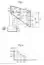
BRIEF DESCRIPTION OF THE DRAWINGSFIG. 1 shows the system schematically;
FIG. 2 is a graph illustrating variation in density with height;
FIG. 3 shows a modification of the system of FIG. 1; and
FIG. 4 illustrates interconnection of transducers in the arrangement of FIG. 3.
DETAILED DESCRIPTION OF THE PREFERRED EMBODIMENTSWith reference first to FIG. 1, there is shown an aircraft fuel tank 1 having an inclined floor 2 and containing three ultrasonic, acoustic height measurement probes 3, 4 and 5 located in different regions of the tank. Each probe 3 to 5 includes a tubular still well 30, 40 and 50 mounted to project substantially vertically upwards from the floor 2 and a piezoelectric ultrasonic transducer assembly 31, 41 and 51 mounted within the still well at its lower end. The still well 30 to 50 is open so that it is filled with fuel to the same height as fuel 6 in the tank. Each transducer 31 to 51 is mounted so that it is immersed in any fuel present and so that, when energized, it transmits a burst of ultrasonic energy upwardly along the still well 30 to 50. When the burst of energy meets the fuel/air interface at the fuel surface 7, a major part of the energy is reflected back down the still well 30 to 50 where it is incident on the transducer 31 to 51 and produces an output signal. The time between transmission of the energy and reception of its reflection is an indication of the height of fuel.
The transducers 31 to 51 in each probe 3 to 5 are connected with a processing unit 20, which is arranged to energize the probes and calculate the height h3, h4 and h5 of fuel 6 at each probe 3, 4 and 5 respectively. The processing unit 20 is also arranged to measure the resonant frequency of each transducer assembly 31 to 51. The processing unit 20 includes a store 21 containing a look-up table relating resonant frequency to density and, using this, it determines the density d3, d4 and d5 at the transducer assembly 31 to 51 in each probe 3, 4 and 5 respectively. The processing unit 20 then produces a model of the variation in density d with height S of the kind shown in FIG. 2. The processing unit 20 uses this information both in calculations of fuel height, to compensate for variations in acoustic velocity with density, and in calculating the total mass of fuel after determining its volume. In this way, the accuracy of measurement of fluid mass can be improved without the need for separate densitometers. The processing unit 20 provides an output representative of mass of fuel to a display or other utilisation means 22.
It is not essential that the same transducers used to measure fluid height be used to measure density. Instead, as shown in FIG. 3, each probe 3′, 4′ and 5′ could have a density-measuring transducer assembly 32′, 42′ and 52′ associated with it in addition to the height-measuring transducer assembly 31′, 41 ′ and 51′. The transducer assemblies 32′, 42′ and 52′ are mounted outside the still wells 30′, 40′ and 50′ and closely adjacent the lower end of the probe where the height-measuring transducer assemblies 31′ to 51′ are located, so that the density is measured as close as possible to the height-measuring transducers. However, it is not essential for the density-measuring transducer assemblies to be located adjacent the probes; they could instead be spaced from the probes.
As shown in FIG. 4, the density-measuring transducer assemblies 32′ to 52′ are preferably connected in parallel with the height-measuring transducer assemblies 31′ to 51′ so that the supply to and from the probe assembly 3′ to 5′ including the density-measuring transducer can be provided along one cable. This arrangement enables two transducer assemblies of different kinds to be used, one being more suited to height measurement and the other having a greater variation in resonant frequency with density. The transducer assemblies in a parallel pair may operate at different frequencies, thereby enabling the processing unit to select between the two transducer assemblies.
It is not essential for the probes to have a still well since they could be used in an open, tubeless configuration, such as of the kind described in U.S. 5,670,710. In such arrangements, the height-measuring transducer assembly could be used to measure the density, or a separate transducer assembly could be used.
Claims
1. A fluid-quantity gauging system comprising: a plurality of acoustic transducer assemblies mounted for immersion in a fluid, and a processor arranged to energize the transducer assemblies and to receive outputs from the transducer assemblies, wherein the processor is arranged to derive from the transducer assemblies signals indicative of density at a plurality of locations within the fluid and signals indicative of height of fluid at a plurality of locations whereby the mass of fluid can be calculated.
2. A fluid-quantity gauging system according to claim 1, wherein the processor is arranged to determine the resonant frequency of some at least of the transducer assemblies, and wherein the processor is arranged to derive the signals indicative of density from the resonant frequency.
3. A fluid-quantity gauging system according to claim 1, wherein the signals indicative of height of fluid and the signals indicative of density are derived from the same transducer assemblies.
4. A fluid-quantity gauging system according to claim 1, wherein the signals indicative of height of fluid and the signals indicative of density are derived from different ones of the transducer assemblies.
5. A fluid-quantity gauging system according to claim 4, wherein the transducer assemblies providing the signals indicative of density are located adjacent those providing the signals indicative of height.
6. A fluid-quantity gauging system according to claim 4, wherein the transducer assemblies providing the signals indicative of density are connected in parallel with the transducer assemblies providing the signals indicative of height.
7. A fluid-quantity gauging system according to claim 1, wherein the transducer assemblies providing the signals indicative of height are each located at a lower end of a respective still well.
8. A fluid-quantity gauging system according to claim 1, wherein the transducer assemblies providing the signals indicative of density are mounted at different heights, and wherein the processor is arranged to model the variation of density with height and to use this in the calculation of the mass of the fluid.
9. A fluid-quantity gauging system comprising: a plurality of acoustic probes, each probe including a still well mounted to project substantially vertically in fluid and an acoustic transducer at a lower end of the still well; a processor; and a connection between the processor and each transducer such that the processor can energize the transducers and receive outputs therefrom, wherein the processor is arranged to derive signals from the transducers indicative of height of fluid at a plurality of locations, and wherein the processor is arranged to determine the resonant frequency of at least one of said transducers and to derive therefrom an indication of the density of the fluid.
10. A fluid-quantity gauging system comprising: a plurality of acoustic probes, each probe including a still well mounted to project substantially vertically in fluid and an acoustic transducer at a lower end of the still well; at least one additional acoustic transducer mounted adjacent the lower end of one of said still wells; a processor; and a connection between the processor and each transducer at the lower end of the still wells such that the processor can energize the transducers and receive outputs therefrom, wherein the processor is arranged to derive signals from the transducers at the lower end of the still wells indicative of height of fluid at a plurality of locations, and wherein the processor is arranged to determine the resonant frequency of said additional transducer and to derive therefrom an indication of the density of the fluid.
11. A fluid-quantity gauging system according to claim 10, wherein the system includes a plurality of said additional transducers, wherein each said additional transducer is located at the lower end of a respective still well, and wherein the processor is arranged to determine the resonant frequency of each said additional transducer.
12. A fluid-quantity gauging system according to claim 11, wherein the additional transducers are connected in parallel with the transducers mounted at the lower end of the respective still wells.
Images & Drawings included:


Sources:
- United States Patent and Trademark Office - verify current appl. status at the USPTO↗
Recent applications in this class:
- » 20220003588 2022-01-06
INVISIBLE INDUSTRIAL INTERNET-OF-THINGS - » 20210140810 2021-05-13
Arrangement for detection of the amount of material in a supply container of a machine for application of material to a field - » 20210140809 2021-05-13
SYSTEM AND METHOD FOR MONITORING LEVEL OF MATERIAL STORED IN RECEPTACLES - » 20210116285 2021-04-22
Capacitive sensor device - » 20210025747 2021-01-28
System and method for liquid level monitoring - » 20210018356 2021-01-21
Systems and methods for liquid-volume measurement in immersion-cooled devices - » 20200326221 2020-10-15
Fluid volume determination enhanced by assessment of vehicle operative state - » 20200141785 2020-05-07
Permeable pavement monitoring system - » 20200103267 2020-04-02
Fuel level display filter algorithm adjust to prevent fuel run out with fuel displayed on gauge - » 20200080882 2020-03-12
SYSTEMS AND METHODS FOR AUTOMATED FLOOD RESPONSE
Recent applications for this Assignee:
- » 20160082219 2016-03-24
Gas-treatment devices - » 20150209537 2015-07-30
MEDICO-SURGICAL TUBE ASSEMBLIES - » 20130144159 2013-06-06
Medical-surgical devices - » 20130085384 2013-04-04
Medical-surgical devices - » 20130042872 2013-02-21
Cuffed medical tubes - » 20120180796 2012-07-19
Tracheostomy Tubes - » 20120152257 2012-06-21
Cuffed medical tubes - » 20110172488 2011-07-14
Medico-surgical devices - » 20100256577 2010-10-07
Needle assemblies and methods - » 20100244432 2010-09-30
Tubes and their manufacture