Tool cabinet fixing and supporting structure
US20050217543A1
2005-10-06
10/817,871
2004-04-06
Abstract:
The present invention discloses a tool cabinet fixing and supporting structure, which comprises at least one shelf, four corner bars disposed at the four corners of the shelf, and a positioning member disposed between the shelf and the corner bars; wherein the positioning member has a connecting surface being coupled to an installing surface of the corner bar and having a limit bolt for supporting a positioning hole disposed on a bottom plate of the shelf. Such an arrangement constitutes the fixing and supporting relation between the corner bars and the shelf. Further, positioning holes are disposed on the installing surface of the corner bar and a transversal board for passing the fastening member through the positioning holes to securely mount the shelf onto the corner bars, and thus constituting an easy-to install tool cabinet with a better supporting strength.
Interested in similar patents?
Get notified when new applications in this technology area are published.
Classification:
A47B47/024 » CPC main
Cabinets, racks or shelf units, characterised by features related to dismountability or building-up from elements made of metal only; Racks or shelf units with shelves between uprights without separate horizontal shelf supports
Description
FIELD OF THE INVENTIONThe present invention relates to a tool cabinet fixing and supporting structure, and more particularly to a tool cabinet providing several layers of open shelves for storing various tools.
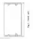
BACKGROUND OF THE INVENTIONPlease refer to FIG. 1 for the P.R.C. Patent Publication No. CN2386927Y, which discloses a traditional tool cabinet assembly structure. Since traditional tool cabinet simply passes a positioning member through a circular positioning hole disposed between a shelf and a corner bar to fix the tool cabinet, the corner bars at the four corners and the shelves cannot be fixed effectively, and it is difficult to assemble the tool cabinet. The patent specification of the aforementioned patent disclosed a tool cabinet assembly structure comprising a pair of shelves and two pairs of vertical components (corner bars). Each shelf further comprises two pairs of horizontal components; wherein each of the horizontal and vertical components has a plurality of rectangular openings, circular openings, bolts, and connecting sections of the rectangular openings; and a screw positioning member having a corner bar limit section disposed at the connecting position of a bolt and a nut for combining each shelf with each vertical component and forming a tool cabinet with stronger assembly structure. However, the assembly structure of such patent still has the following shortcomings to overcome:
-
- 1. The vertical component (corner bar) must support the total weight of the shelves and the tools placed on the shelves. Therefore, the rigidity of the corner bar becomes a key issue; however, there are openings on the vertical component according to that patented technology. The weight actually borne by the vertical component is an issue if the number of required shelves increases. Furthermore, the openings also ruin the overall artistic appearance and the rough edges of the openings if not trimmed may cut users easily.
- 2. Since the bolt is formed by bending inwards, it bears a lighter weight. In addition, there is a tolerance for the bending angle of each bolt, so that when the shelf is put onto the bolts of the vertical component, the vertical component and the horizontal component of each shelf are not fully attached, and thus it is unable to secure the screws. As for traditional tool cabinets, such a technology only provides a partial improvement, but does not achieve the effect of mounting the shelves securely into a fixed position on the tool cabinet.
- 3. There is another shortcoming related to the design of the bolt and the transportation and storage of the tool cabinet. Since the bolt is protruded to create a gap between the vertical component and the bolt, therefore the vertical components cannot be stacked on each other. Such an arrangement increases transportation costs and storage space.
The primary objective of the present invention is to overcome the foregoing shortcomings and avoid the existing deficiencies by providing a tool cabinet that makes use of a positioning member disposed between the shelf and the corner bars to fix the positioning member with its installing surface to the inner wall of the corner bars without changing the structure of the current existing corner bars. A limit bolt is extended from the positioning member to receive a positioning hole disposed at the bottom of the shelf to constitute a positioning and supporting relation with the corner bars. Since the supporting surface is located at the bottom surface of the shelf, therefore the shelf and the connecting surface of the corner bars can be attached better to position more effectively. Further, a positioning hole is disposed on the installing surface of the corner bar and the transversal board, and a positioning member is used to pass through the positioning hole to constitute a coupling relation between the shelf and the corner bars, and thus forming an easy-to install tool cabinet with better supporting strength.
BRIEF DESCRIPTION OF THE DRAWINGSFIG. 1 is a cross-sectional view of a prior-art tool cabinet assembly.
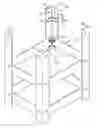
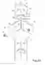
FIG. 2 is a perspective view of the present invention.
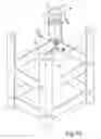
FIG. 3A is a view of the disassembled parts of the structure according to the present invention.
FIG. 3B is an enlarged view of the connected position as depicted in FIG. 3A.
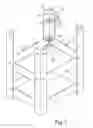
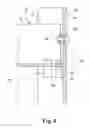
FIG. 4 is a cross-sectional view of Section 4-4 as depicted in FIG. 2.
DETAILED DESCRIPTION OF THE PREFERRED EMBODIMENTSTo make it easier for our examiner to understand the objective of the invention, its structure, innovative features, and performance, we use a preferred embodiment and the attached drawings for the detailed description of the invention.
Please refer to FIGS. 2, 3A, and 3B for the tool cabinet positioning and supporting structure according to the present invention. The tool cabinet comprises at least one shelf 10 and four corner bars 20 disposed at four corners of the shelf 10; wherein the shelf 10 comprises four transversal boards 11, 12 adjacent to the corner bars 20 and a bottom board 13 disposed under the transversal boards 11, 12. The shelf 10 has two corresponding transversal boards 11 with two installing surfaces 21, 22, and the bottom board 13 has a positioning hole 131 at the position of the installing surfaces 21, 22. A positioning member 30 is disposed between the shelf 10 and the corner bars 20, and has an installing surface 31 coupled to the installing surfaces 21, 22 of the corner bars 20. A limit bolt 32 is extended from the positioning hole 131 of the positioning member 30 to form the positioning and supporting relation of the shelf 10 and the corner bars 20. A positioning hole 211, 111 is disposed on the installing surfaces 21, 22 of the corner bars 20 and the transversal boards 11, 12. A fastening member 40 passes through the positioning hole 211, 111 to constitute the coupling relation of the shelf 10 and the corner bars 20. During assembly, it only required to place the shelf 10 between the four corner bars 20. By the limit bolt 32 being partially extended from the top of the installing surface 31 of the positioning member 30, the remaining portion at the top of the installing surface 31 is the blocking surface 33 for supporting the shelf 10. Therefore, when the bottom board 13 of the shelf 10 uses the positioning hole 131 to connect the limit bolt 32, the bottom board 13 is supported by the blocking surface 33. In FIG. 4, it obviously shows that since there is no component blocking the transversal boards 11, 12 of the shelf 10 and the installing surfaces 21, 22 of the corner bars 20, and, therefore it provides a better attaching effect. Then, the fastening member 40 is used to pass through the positioning holes 211, 111. The fastening member 40 comprises a screw, a washer, and a nut; wherein the positioning hole 211 disposed on the installing surfaces 21, 22 is a rectangular adjusting hole for providing sufficient space to secure and fine tune the fastening member 40.
Refer to FIG. 2 for a view of the assembly and compare such assembly with the prior art as shown in FIG. 1. The corner bars 20 according to the present invention does not come with a bolt design, and thus maintains a full rigidity. The positioning effect of the positioning member 30 according to the present invention is achieved by the bottom board 13 together with the limit bolt 32 and the positioning hole 131, and thus will not cause any gap. Furthermore, the design of the blocking surface 33 provides the effect of supplementing the support of the shelf 10 in addition to the coupling effect with the fastening member 40.
While the invention has been described by way of example and in terms of a preferred embodiment, it is to be understood that the invention is not limited thereto. To the contrary, it is intended to cover various modifications and similar arrangements and procedures, and scope of the appended claims therefore should be accorded the broadest interpretation so as to encompass all such modifications and similar arrangements and procedure.
Claims
1. A tool cabinet fixing and supporting structure, comprising at least one shelf and four corner bars disposed at four corners of said shelf, characterized in that:
said shelf comprises four transversal boards adjacent to said corner bars, a bottom board disposed under said transversal boards, and said shelf being coupled to two installing surfaces disposed on two corresponding transversal boards, and said bottom board having a positioning hole disposed on said installing surface and a positioning member disposed between said shelf and said corner bars, and said positioning member having a limit bolt extended from said positioning hole for being installed to said limit bolt to constitute a positioning and supporting relation between said shelf and said corner bars, and a positioning hole disposed on said installing surface of said corner bar and said transversal board for passing a fastening member through said positioning hole to constitute a coupling relation between said shelf and said corner bars.
2. The tool cabinet fixing and supporting structure of claim 1, wherein said positioning hole disposed on said installing surface is a rectangular adjusting hole.
3. The tool cabinet fixing and supporting structure of claim 1, wherein said limit bolt is extended from the top of said installing surface of said positioning member and the remaining portion of said installing surface is a blocking surface for supporting said shelf.
4. The tool cabinet fixing and supporting structure of claim 1, wherein said fastening member comprises a screw, a washer, and a nut.
Images & Drawings included:
Sources:
- United States Patent and Trademark Office - verify current appl. status at the USPTO↗
Recent applications in this class:
- » 20220110445 2022-04-14
Storage rack - » 20190223592 2019-07-25
Cabinet system and method for assembling a cabinet system - » 20120298607 2012-11-29
Sectional rack - » 20120067838 2012-03-22
Industrial frame rack support assembly - » 20110220603 2011-09-15
Easily assembled shelving system of small overall size - » 20100252520 2010-10-07
STORAGE RACK - » 20090314731 2009-12-24
Storage rack - » 20090218301 2009-09-03
Universal rack mountable shelf - » 20090152225 2009-06-18
Shelving system - » 20070131628 2007-06-14
UNIVERSAL RACK-MOUNTABLE SHELF