A dew machine or a dew making machine
US20050223733A1
2005-10-13
10/907,133
2005-03-22
Abstract:
The purpose of invention is to create the dew machine by which the humidity in the air is liquefied for consumption purposes. A dew machine following this document is used for condensing water from humidity in air for consumption. The working principle of this machine is as same as that of a general air-conditioning unit, but we take care of the water that is liquefied from the condenser unit, not the cooled air. For the main structures of this machine, there is an air filter at the top of a condensing tower unit. Inside the rounded-tube condensing tower, the rod that is wrapped by twisted stainless steel sheet is inserted in a refrigerating cylinder that is enclosed with stainless steel sheet. Both of the rod and the refrigerating cylinder are together inserted in the insulated cylinder. The bottom end of the condensing tower is welded with a water tank near an air blower. The blower is used for forcing the air pass throughout the rounded-tube condensing tower from the top to bottom end. At the bottom side of the condensing tower, a refrigerant's tube is directly connected to a compressor that compresses the refrigerant to supply the whole system, and, at the head area of the condensing tower, there is a refrigerant's discharge tube running to compressor. During this process, the relative humidity of the inlet air goes higher until it reaches the dew point. After that, the water vapor in the air saturates and becomes the water droplets dropping down into the water tank, which located at the bottom of the evaporative condenser tower. A faucet is also welded with the water tank near which the air blower is installed and sucks the dehumidified air out the system.
Assignee:
- PAKORN TAECHAKWANIDCHWAL 1 🇹🇭 BANGKOK, Thailand
Interested in similar patents?
Get notified when new applications in this technology area are published.
Classification:
F24F1/42 » CPC main
Room units for air-conditioning, e.g. separate or self-contained units or units receiving primary air from a central station; Separate outdoor units, e.g. outdoor unit to be linked to a separate room comprising a compressor and a heat exchanger characterised by the use of the condensate, e.g. for enhanced cooling
F24F13/222 » CPC further
Details common to, or for air-conditioning, air-humidification, ventilation or use of air currents for screening; Means for preventing condensation or evacuating condensate for evacuating condensate
F24F8/117 » CPC further
Treatment, e.g. purification, of air supplied to human living or working spaces otherwise than by heating, cooling, humidifying or drying by separation, e.g. by filtering using wet filtering
Y02A50/20 » CPC further
in human health protection, e.g. against extreme weather Air quality improvement or preservation, e.g. vehicle emission control or emission reduction by using catalytic converters
Description
This invention relates to the knowledge in the field of Mechanical Engineering (Refrigeration and Machine Design).
The working principle of common air-conditioners is exchanging heat between air that is sucked into the system and refrigerant that are running through tubes. After heat transfer, the conditioned air is supplied to the room and makes the room cooler. For the humidity in air, it becomes water droplets and rests on the outer surface of the refrigerant's tubes and the fins of a heat exchanger. After that, the water droplet drains. As we know well, all types of air-conditioning units must have draining water which is useless because most of refrigerant's tubes that are made from copper and the fins of the heat exchanger set that are made from aluminum are easily oxidized, so the water droplets that condense on their shell are contaminated and not safe enough for consume. From the above principle that relates to refrigeration system in the air-conditioner, we would like to propose the novel designed machine, the dew machine or the dew making machine, whose copper and aluminum components are replaced by stainless steel parts for hygiene and sanitary objectives.
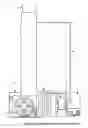
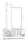
The complete drawing of the dew machine is illustrated in FIG. 1. The air filter (1) lies on the top of this machine to clean the air that is sucked by the centrifugal flow fan (5) that sits near the water tank (4) before it enters the rounded-tube condensing tower (2). This tower (2) is a round-shaped duct with two open ends. Inside it, there is the stainless steel rod (10) in FIG. 2 that is wrapped by the twisted stainless steel sheet (11) to force the air to flow swirlingly along the path between the gaps of the sheet. Moreover, this rod (10) is centered with the refrigerating cylinder (12) that is bound by the coiled stainless steel sheet to let the refrigerant flow in between the sheet. This round evaporative cylinder (12) is covered by the insulated cylinder (13). The refrigerant circulates into the cylinder from the bottom (14) to the top (15) of the side view of this unit to refrigerate the chamber of the tower (2). After the inlet air that is sucked through internal surface of the evaporative condenser tower (2) is conditioned, its relative humidity reaches the dew point and lets the humidity in it condense and drop into the water tank (4) that also has a faucet (not displayed in the figure). One end of refrigerant's tube (3) is welded with the insulated cylinder (13) at the position of (14) in FIG. 4. Another is linked with the condenser coil unit (6). The air ventilating axial flow fan (7) is installed near it to lower the temperature of the refrigerant. Before the refrigerant runs into the condenser unit (6), it is compressed by the compressor (8). The refrigerant that runs the exit of the evaporative condenser tower (2) at the position of (15) circulates to the suction side of the compressor (8).
Claims
1. An air filter (1) is on the head of an evaporative condenser tower (2). There is a water tank (4) at the bottom of the condensing tower (2) and an air blower (5) is installed near the water tank (4). A refrigerant's tube runs from the bottom end of the condensing tower (2) to a compressor (8) near which an air ventilating fan is located. The condenser unit (6) and the compressor (8) are bridged together by the refrigerant's tube (3). Suction pipe (9) line to compressor (8) is connected to the top of the condensing tower (2).
2. Characterized in that the said the condensing tower (2) consists of a set of specifically designed components. The first component is a stainless steel rod (10) that is wrapped by twisted stainless steel sheet (11) and it is inserted in a refrigerating cylinder (12). Besides, this refrigerating cylinder (12) is also enclosed in an insulated cylinder (13) to reduce heat transfer between itself and its environment. Refrigerant is pumped through the condensing tower (2) from the bottom to the top of this unit.
Images & Drawings included:


Sources:
- United States Patent and Trademark Office - verify current appl. status at the USPTO↗
Recent applications in this class:
- » 20250035324 2025-01-30
SYSTEMS AND METHODS FOR AIR CONDITIONER SUBCOOLING - » 20240219042 2024-07-04
SYSTEM FOR EVAPORATIVE COOLING OF AN AIR CONDITIONING CONDENSER OR A RADIATOR TO ENHANCE EFFICIENCIES - » 20240219041 2024-07-04
SPRAYING DEVICE AND METHOD OF CONTROLLING THE SAME FOR IMPROVING THERMAL EFFICIENCY OF AIR CONDITIONER - » 20240068678 2024-02-29
METHOD AND APPARATUS FOR IMPROVING THERMAL EFFICIENCY OF AIR CONDITIONER - » 20230332778 2023-10-19
Air conditioning system - » 20220120452 2022-04-21
BOOTH - » 20220034525 2022-02-03
SYSTEM FOR EVAPORATIVE COOLING OF AN AIR CONDITIONING CONDENSER OR A RADIATOR TO ENHANCE EFFICIENCIES - » 20200271334 2020-08-27
WATER COOLING SYSTEM FOR A/C UNIT - » 20190162427 2019-05-30
AIR CONDITIONING ECONOMIZER - » 20170159950 2017-06-08
Compressor