Plastic product dispenser body with moving bottom
US20050229945A1
2005-10-20
11/086,208
2005-03-23
Abstract:
The hollow body includes a sidewall and a supporting bottom. The body has a part, forming all or part of the bottom, free to move in the axial direction under a manual axial force applied thereon, due to a portion of the flexible wall surrounding the moving part and the thickness being chosen such that the flexible wall is resilient in bending. The flexible wall is an annular portion inscribed within a circle typically centred on the axial direction of the body. The body is formed from a plastic material that can be subjected to resilient bending. The axial manual pressure applied on the moving part enables reliable and repeated displacement thereof, and triggers a technical effect inside the hollow body, due to an auxiliary part.
Interested in similar patents?
Get notified when new applications in this technology area are published.
Classification:
A45D40/0075 » CPC main
Casings or accessories for storing or handling solid or pasty toilet or cosmetic substances, e.g. shaving soap, lipstick, make-up; Jars with dispensing means
B65D43/0231 » CPC further
Lids or covers for rigid or semi-rigid containers; Removable lids or covers without integral tamper element secured by rotation only on the outside, or a part turned to the outside, of the mouth of the container
B65D83/0005 » CPC further
Containers or packages with special means for dispensing contents Containers or packages provided with a piston or with a movable bottom or partition having approximately the same section as the container
A45D33/02 » CPC further
Containers or accessories specially adapted for handling toilet or cosmetic powder with dispensing means, e.g. sprinkling means
Description
DOMAIN OF THE INVENTIONThe invention relates to the domain of packaging for pasty cosmetic products such as creams, or products in the divided state such as makeup powders.
It is particularly applicable to plastic dispenser bodies, for example pots for cosmetic products provided with a bottom and a lid typically screwed to the bottom.
It may also relate to packaging of food products or pharmaceutical products.
STATE OF THE ARTCommercial pots usually used comprise a plastic body consisting of a bottom and a lateral skirt, for which the top opening is threaded, and a threaded cap closing off the top opening.
Problems that Arise
Firstly, plastic bodies or pots according to the state of the art typically have a rigid bottom with a depth usually varying from 3 to 6 cm or even more, such that it is difficult to access all the product contained in the pot and to achieve a high restitution rate of the product contained in the said pot.
Secondly, in many cases, the pasty product is collected from the said pot with the fingers and is then applied usually to the face or to the skin. This type of collection and this manual application make the user's fingers dirty and possibly cause pollution of the product to be applied.
Furthermore, an increasing number of dispensers include complementary means of facilitating dispensing or application of the said product. These complementary means may also form means of heating or cooling the product to be dispensed.
Traditional dispenser bodies or pots are not suitable for the addition of such complementary means.
DESCRIPTION OF THE INVENTIONAccording to the invention, the hollow body of a dispenser for a product, typically a cosmetic product, typically with a symmetry of revolution about an axial direction of the said body, comprises a sidewall and a supporting bottom, the said sidewall having an upper edge typically provided with an outer thread, forming an opening and is characterised in that:
-
- a) the said body comprises a part, forming all or part of the said bottom, free to move in the axial direction under a manual axial force applied on the said part, due to a portion of the flexible wall of the said sidewall or the said bottom surrounding the said moving part and the thickness being chosen such that the said flexible wall is resilient in bending and forms a hinge,
- b) the said flexible wall portion is an annular portion inscribed within a circle typically centred on the said axial direction of the said body,
- c) the said body is formed from a plastic material that can be subjected to the said resilient bending for the said flexible wall portion,
- such that the said stress or manual axial pressure applied on the said moving part pushes it into the said body along an axial displacement, the said moving part coming out of the said body and typically moving into its original axial position as soon as the said manual pressure is removed.
The combination of means according to the invention solves the problems that arise.
The applicant has observed that it is thus possible to have a plastic dispenser body with a bottom with an axial travel distance such that a technical effect can be implemented or triggered, this technical effect being of any nature among previously known technical effects.
This technical effect may relate to dispensing of the said product. Thus, for example, axial displacement of the said moving part may act as a propellant for the said product, displacement that can be repeated as often as required during dispensing or application of the said product, the product being expelled when the said manual pressure is applied, the said body possibly being closed by a mesh, and air entering in the said body during elastic return of the said moving part.
This technique may also relate to an operation to be carried out before the actual dispensing itself; for example, it may be to trigger mixing of two products, or to trigger heating or cooling of the said product.
Since an increasing number of dispensers include complex technical functions, it is important to have dispenser bodies that are suitable for integration of such technical functions.
DESCRIPTION OF THE FIGURESAll Figures relate to bodies (1) according to the invention forming pots.
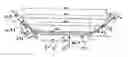
FIGS. 1a to 1e relate to a body (1) with a flared sidewall (2), while FIGS. 2a to 2c and 3a to 3b relate to another body (1) with a straight sidewall (2).
FIG. 1a is a section through the body (1) in a vertical plane including the axial direction (10) of the said body.
FIG. 1b is a side view.
FIG. 1c is a top view.
FIG. 1d is an enlarged view of the top straight part surrounded by circular dashed lines in FIG. 1a.
FIG. 1e is an enlarged view of the lower part of FIG. 1a, the part is surrounded by dashed lines in the form of a rectangle.
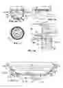
FIG. 2a shows a section corresponding to that in FIG. 1a in the left part, and a side view corresponding to that in FIG. 1b in the right part.
FIG. 2b is a top view.
FIG. 2c corresponds to FIG. 2a and represents a dispenser (6) comprising the said body (1) with a lid (4) and an auxiliary part (5) inside the said body.
FIGS. 3a and 3b are partial enlarged views of the left part in FIG. 2c.
FIG. 3a represents the top part of the dispenser (6) with its lid (4) and FIG. 3b represents the bottom (3).
DETAILED DESCRIPTION OF THE INVENTIONAccording to the invention, the said plastic material may comprise a blend of two plastic materials, a first plastic material with a said high bending modulus, with a bending modulus of more than 350 MPa, and a second plastic material with a said low bending modulus, the bending modulus being less than 350 MPa.
The content by weight of the said first plastic material may vary from 40% to 80%, and content by weight of the said second plastic material may vary from 60% to 20%. The said first plastic material may be a thermoplastic material typically chosen from among PE, PP, and the said second plastic material is an elastomer, typically SEBS.
According to one embodiment of the invention illustrated in FIGS. 1a to 1e, the said sidewall (2) of the said body (1) may be a flared wall (2′).
In this body:
-
- a) the said sidewall (2) may form a sequence of several circular wall portions, starting from the said upper edge and working towards the bottom, typically three walls P1 (21), P2 (22) and P3 (23), with outside diameters D1, D2 and D3 in decreasing order of diameter, each of the said diameters being taken at the top part of the said corresponding wall (21, 22, 23),
- b) the said sequence of several circular wall portions, typically 3 walls P1 (21), P2 (22) and P3 (23), may have decreasing average thicknesses E1, E2 and E3,
- c) the said bottom (3) may have a diameter D4<D3 and a thickness E4 equal to at least 1.5E3,
- d) the said thickness E3 may be chosen such that the said relatively thin wall portion P3 (23) forms the said flexible wall portion (11) forming the said hinge and thus the said bottom (3) forms the said moving part (12).
Similarly, in the said body (1):
-
- a) D2/D1 may be between 0.80 and 0.92,
- b) D2/D3 may be between 0.6 and 0.8,
- c) D3/D4 may be between 0.5 and 0.7,
- and the said sidewall (2) may have an outside profile typically corresponding to a segment of a parabola as shown in FIGS. 1a and 1b.
The height H of the said body (1) may typically vary from 30 mm to 60 mm and the diameter D1 that is larger varies from 40 mm to 70 mm.
Beside, in the said body (1);
-
- a) the said average thickness E1 of the wall P1 or the upper wall may be between 5 mm and 2 mm,
- b) the said average thickness E2 of the wall P2 or the median wall may be between 1 mm and 2 mm,
- c) the said average thickness E3 of the wall P3 or the lower wall may be between 0.3 mm and 1.
According to the invention, and as shown in FIG. 1e, the said walls P2 (22) and P3 (23) may have a typically constant thickness E2 and E3, the said walls P2 (22) and P3 (23) being connected through an intermediate wall P23 (24) with a variable thickness E23 over its height H23, the said height H23 being between 2 and 5 mm.
As can be seen in FIG. 1a, the said wall P1 (21) or upper wall may have a constant inside diameter over its entire height H1, the said height H1 varying from 12 mm to 30 mm, and preferably from 15 mm to 25 mm.
As can be seen in FIG. 1d, in which the said upper edge (20) or the top part of the said wall P1 (21) may have a click fit means (25) that will cooperate with an auxiliary part (5), the said auxiliary part (5) typically closing off the said opening (201) and forming means of application of the said product.
In FIG. 1d, this means is a circular groove into which an add-on part click fits to obstruct the said opening (201) and possibly form a means of application of the said product.
As illustrated in FIG. 1e, the said wall P3 (23) or the lower wall may have an average angular slope α3 with the said typically plane bottom (3) varying from 20° to 40°, the said wall P2 having an average angular slope α2 such that α3=α2+Δα where Δα varies from 10° to 30°.
According to another embodiment of the invention illustrated in FIGS. 2a to 3b, the said sidewall (2) may form a typically cylindrical straight skirt (2″) connected to the said bottom (3), the said bottom (3) comprising the said flexible wall portion (11) and the said moving part (12).
The said straight skirt (2″) may have an average thickness E1 between 5 mm and 2 mm, and the said bottom (3) may include:
-
- a) a peripheral part F1 (30) with the said average thickness E1,
- b) a median part F2 (31) with thickness E2 between 0.3 mm and 1 forming a portion of the flexible wall (11),
- c) a central part F3 (32) with thickness E3 between 1 mm and 2 mm, the said central part F3 (32) forming the said moving part (12) of the said bottom.
The said median part F2 (31) may form or include an outer re-entrant ring (310) with a slope β1 varying from 30° to 70° and a projecting inner ring (311) with a slope β2 varying from −10° to 50°.
Preferably, as illustrated in FIG. 3b, when the said stress or manual pressure (7) is not applied, the said central part F3 (31) may be offset inwards with respect to the said peripheral part F1 with a height h varying from 2 to 5 mm, so as to avoid or limit the risk of a force being accidentally applied on the said central part F3 (31).
As illustrated also in FIG. 3b, the said straight skirt (2″) and the said bottom (3) may have a radius of curvature of the fillet R varying from 5 to 15 mm, and typically from 6 mm to 10 mm.
According to the invention, the said straight skirt (2″) may have a round or oval or square or rectangular cross-section, taken perpendicular to the said axial direction. In fact, the skirt may have any shape.
Regardless of the embodiment of the invention, the said body (1) may be a moulded part, typically formed by injection of the said plastic material.
The said axial displacement when the said stress or manual pressure (7) is applied to the said moving part (12), pushes it into the said body (1), and may cover an axial distance varying from 2 mm to 10 mm, and typically from 3 to 6 mm.
This axial distance is chosen depending on the technical functions built into the said body that require the said auxiliary part (6).
Another purpose of the invention is a product dispenser containing a body (1) according to the invention, a means (4) of closing off the said opening and typically an auxiliary part (5) that depends on the said axial displacement for its operation.
EXAMPLE EMBODIMENTSFIGS. 1a to 1e show a first example embodiment of a body (1) according to the invention.
In this example, the said body (1) is a pot with a flared wall (2′) that can contain a pasty product or a solid product in the divided state, such as a makeup powder. The opening (201) of this body may be closed off by an auxiliary part (5) (not shown in FIGS. 1a and 1d) that will be used for application of the product.
In this example, part of the sidewall (2, 2′) forms the said flexible wall portion (11), while the said bottom (3) forms the said moving part (12).
This pot may be closed off by a lid provided with an inner thread that will cooperate with the thread (200) of the upper edge (20) of the sidewall (2) of the said body (1).
FIGS. 2a to 3b form a second example embodiment of a body (1) according to the invention.
In this example, the said body (1) is a pot with a straight skirt (2″) and the said bottom includes the said flexible wall portion (11) and the said moving part (12).
The figures show the said auxiliary part (5) that is a device with a metallic wall for which axial displacement will trigger a physical process, for example such as mixing of two products contained in the said body, separately until the said manual pressure is applied.
ADVANTAGES OF THE INVENTIONThe invention provides a means of making a body made of a plastic material, part of which forms a sort of sealed entry door, enabling reliable and repeated action on the content(s) of the said body, typically using an auxiliary part, and typically in order to either propel the product towards the opening of the body for application, or to mix several products.
But the invention is not limited to these two technical effects alone.
More and more packagings incorporate complex technical functions, either for traceability of products, to make tamper resistant containers, to enable guaranteed identification, protection against theft, etc., and these technical functions may be passive or may possibly be activated at a given moment of the life of the product, knowing that such activation may require a simple elementary means such as axial displacement, knowing that electromagnetic waves or signals can be stopped by metal walls of some packaging means.
| List of marks | |
| Dispenser body | 1 | |
| Axial direction | 10 | |
| Flexible wall portion | 11 | |
| Moving part | 12 | |
| Sidewall of 1 | 2 | |
| Flared wall | 2′ | |
| Straight skirt | 2″ | |
| Upper edge | 20 | |
| Outer thread | 200 | |
| Opening | 201 | |
| Portion P1 of 2 | 21 | |
| Portion P2 of 2 | 22 | |
| Portion P3 of 2 | 23 | |
| Intermediate wall P23 | 24 | |
| Click fit means | 25 | |
| Bottom of 1 | 1 | |
| Peripheral part F1 | 30 | |
| Median part F2 | 31 | |
| Outer ring | 310 | |
| Inner ring | 311 | |
| Central part F3 | 32 | |
| Lid | 4 | |
| Lower edge | 40 | |
| Inner thread | 400 | |
| Seal | 41 | |
| Auxiliary part | 5 | |
| Dispenser = 1 + 4 + 5 | 6 | |
| Manual axial pressure | 7 | |
Claims
1. Hollow body (1) of a dispenser (6) for a cosmetic product, typically a cosmetic product, typically with a symmetry of revolution about an axial direction (10) of the said body, comprising a sidewall (2) and a supporting bottom (3), the said sidewall (2) having an upper edge (20) typically provided with an outer thread (200), forming an opening (201), characterised in that:
a) the said body (1) comprises a part (12), forming all or part of the said bottom (3), free to move in the axial direction under a manual axial force applied on the said part (12), due to a portion of the flexible wall (11) of the said sidewall (2) or the said bottom (3) surrounding the said moving part (12) and the thickness being chosen such that the said flexible wall is resilient in bending and forms a hinge,
b) the said flexible wall portion (11) is an annular portion inscribed within a circle typically centred on the said axial direction (10) of the said body (1),
c) the said body (1) is formed from a plastic material that can be subjected to the said resilient bending for the said flexible wall portion (11), such that the said stress or manual axial pressure (7) applied on the said moving part (12) pushes it into the said body (1) along an axial displacement, the said moving part (12) coming out of the said body (1) and typically moving into its original axial position as soon as the said manual pressure (7) is removed,
d) the said axial displacement, when the said stress or manual pressure (7) is applied to the said moving part (12) and pushes it into the said body (1), is an axial distance varying from 2 mm to 10 mm.
2. Dispenser body according to claim 1, in which the said plastic material comprises a blend of two plastic materials, a first plastic material with a said high bending modulus, with a bending modulus of more than 350 MPa, and a second plastic material with a said low bending modulus, the bending modulus being less than 350 MPa.
3. Dispenser body according to claim 2 in which the said first plastic material has a content by weight varying from 40% to 80%, and the content by weight of the said second plastic material varying from 60% to 20% respectively.
4. Dispenser body according to claim 2, in which the said first plastic material is a thermoplastic material typically chosen from among PE, PP, and the said second plastic material is an elastomer, typically SEBS.
5. Dispenser body according to claim 1 in which the said sidewall (2) is a flared wall (2′), and in which:
a) the said sidewall (2) forms a sequence of several circular wall portions, starting from the said upper edge and working towards the bottom, typically 3 walls P1 (21), P2 (22) and P3 (23), with outside diameters D1, D2 and D3 in decreasing order of diameter, each of the said diameters being taken at the top part of the said corresponding wall (21, 22, 23),
b) the said sequence of several circular wall portions, typically 3 walls P1 (21), P2 (22) and P3 (23), may have decreasing average thicknesses E1, E2 and E3,
c) the said bottom (3) has a diameter D4<D3 and a thickness E4 equal to at least 1.5E3,
d) the said thickness E3 is chosen such that the said relatively thin wall portion P3 (23) forms the said flexible wall portion (11) forming the said hinge and thus the said bottom (3) forms the said moving part (12).
6. Dispenser body according to claim 5, in which:
a) D2/D1 is between 0.80 and 0.92,
b) D2/D3 is between 0.6 and 0.8,
c) D3/D4 is between 0.5 and 0.7,
and in which the said sidewall (2) has an outside profile typically corresponding to a segment of a parabola.
7. Dispenser body according to claim 5, in which the height H of the said body (1) typically varies from 30 mm to 60 mm and diameter D1 that is larger varies from 40 mm to 70 mm.
8. Dispenser body according to claim 5, in which:
a) the said average thickness E1 of the wall Pi or the upper wall is between 5 mm and 2 mm,
b) the said average thickness E2 of the wall P2 or the median wall is between 1 mm and 2 mm,
c) the said average thickness E3 of the wall P3 or the lower wall is between 0.3 mm and 1.
9. Dispenser body according to claim 5, in which the said walls P2 (22) and P3 (23) have a typically constant thickness E2 and E3, the said walls P2 (22) and P3 (23) being connected through an intermediate wall P23 (24) with a variable thickness E23 over its height H23, the said height H23 being between 2 and 5 mm.
10. Dispenser body according to claim 5, in which the said wall P1 (21) or upper wall has a constant inside diameter over its entire height H1, the said height H1 varying from 12 mm to 30 mm, and preferably from 15 mm to 25 mm.
11. Dispenser body according to claim 5, in which the said upper edge (20) or the top part of the said wall Pi (21) has a click fit means (25) that will cooperate with an auxiliary part (5), the said auxiliary part (5) typically closing off the said opening (201) and forming means of application of the said product.
12. Dispenser body according to claim 5, in which the said wall P3 (23) or the lower wall has an average angular slope α3 with the said typically plane bottom (3) varying from 20° to 40°, the said wall P2 having an average angular slope α2 such that α3=α2+Δα where Δα varies from 10° to 30°.
13. Dispenser body according to claim 1, in which the said sidewall (2) forms a typically cylindrical straight skirt (2″) connected to the said bottom (3), the said bottom (3) comprising the said flexible wall portion (11) and the said moving part (12).
14. Dispenser body according to claim 13, in which the said straight skirt (2″) has an average thickness E1 between 5 mm and 2 mm, and the said bottom (3) includes:
a) a peripheral part F1 (30) with the said average thickness E1,
b) a median part F2 (31) with thickness E2 between 0.3 mm and 1 forming a portion of the flexible wall (11),
c) a central part F3 (32) with thickness E3 between 1 mm and 2 mm, the said central part F3 (32) forming the said moving part (12) of the said bottom.
15. Dispenser body according to claim 14, in which the said median part F2 (31) forms or includes an outer re-entrant ring (310) with a slope β1 varying from 30° to 70° and a projecting inner ring (311) with a slope β2 varying from −100 to 500.
16. Dispenser body according to claim 14, in which, when the said stress or manual pressure (7) is not applied, the said central part F3 (31) may be offset inwards with respect to the said peripheral part F1 by a height h varying from 2 to 5 mm, so as to avoid or limit the risk of a force being accidentally applied on the said central part F3 (31).
17. Dispenser body according to claim 12, in which the said straight skirt (2″) and the said bottom (3) have a radius of curvature of the fillet R varying from 5 to 15 mm, and typically from 6 mm to 10 mm.
18. Dispenser body according to claim 12, in which the said straight skirt (2″) has a round or oval or square or rectangular cross-section, taken perpendicular to the said axial direction.
19. Dispenser body according to claim 1, in which the said body (1) is a moulded part, typically formed by injection of the said plastic material.
20. Dispenser body according to claim 1, in which the said axial displacement is an axial distance varying from 3 to 6 mm.
21. Product dispenser comprising a body (1) according to claim 1, a means (4) of closing off the said opening and typically an auxiliary part (5) that depends on the said axial displacement for its operation.
Images & Drawings included:


Sources:
- United States Patent and Trademark Office - verify current appl. status at the USPTO↗
Recent applications in this class:
- » 20240341446 2024-10-17
CLOSURE WITH A DETACHABLE APPLICATOR AND CONTAINER - » 20240065415 2024-02-29
VACUMM BOTTLE WITH A PLURALITY OF LIQUID OUTPUTS - » 20230103213 2023-03-30
Cosmetic product dispenser pot with a stacked base, refill and cover - » 20220167725 2022-06-02
Cosmetic container - » 20200205550 2020-07-02
BEAD CREAM COSMETIC STORAGE CONTAINER - » 20190191847 2019-06-27
Micro pump vessel - » 20190174898 2019-06-13
COSMETIC CONTAINER - » 20190166977 2019-06-06
COMPACT CONTAINER HAVING RING BUTTON MEMBER PROVIDED THEREON AND HAVING DISCHARGE PLATE FORMED THROUGH INSERT INJECTION MOLDING - » 20190150591 2019-05-23
PORTABLE CONTAINER FOR CONTAINING FOUNDATION CREAM - » 20190098985 2019-04-04
COSMETIC CONTAINER