Exercise apparatus
US20050245366A1
2005-11-03
10/834,831
2004-04-30
Abstract:
Exercise apparatus for exercising a part of the human body has a main frame with a base, an upright leg at the front and an inclined connecting leg extending between an upper part of the leg and the base. An exercising lever has a base, a forward portion extending upwardly and forwardly and a rear portion extending rearwardly and upwardly. At the upper end of the forward portion it is pivotally attached through a main frame. At the upper end of a rear portion is a transverse leg engaging member. Resistance means extends between the exercise lever and a main frame and provide resistance to the pivoting of the exercise lever. A support structure extends above the upper part of the main frame for support of the upper part of the body of a user.
Interested in similar patents?
Get notified when new applications in this technology area are published.
Classification:
A63B23/0482 » CPC main
Exercising apparatus specially adapted for particular parts of the body for limbs, i.e. upper or lower limbs, e.g. simultaneously for lower limbs primarily by articulating the hip joints
A63B21/4047 » CPC further
Exercising apparatus for developing or strengthening the muscles or joints of the body by working against a counterforce, with or without measuring devices; Interfaces with the user related to strength training; Details thereof characterised by the movements of the interface Pivoting movement
A63B23/0429 » CPC further
Exercising apparatus specially adapted for particular parts of the body for limbs, i.e. upper or lower limbs, e.g. simultaneously for lower limbs involving a bending of the knee and hip joints simultaneously with guided foot supports moving parallel to the body-symmetrical-plane by being cantilevered about a horizontal axis
A63B23/03508 » CPC further
Exercising apparatus specially adapted for particular parts of the body for limbs, i.e. upper or lower limbs, e.g. simultaneously For a single arm or leg,
A63B2208/0295 » CPC further
Characteristics or parameters related to the user or player posture on hands and feet
Description
FIELD OF THE INVENTIONThis invention relates to exercise apparatus and in particular, though not exclusively, to exercise apparatus for exercising the muscles at the upper part of a users legs.
BACKGROUND OF THE INVENTIONVarious machines exist for exercising legs and other body parts. Typical of such machines is that described in U.S. Pat. No. 6,206,809. In this machine a user lies on their back on a pad, grasps arms extending up from the machine bed, above the users head. The user positions legs under a movable pad mounted on a pivotable framework. Pushing up by the legs on the movable pad pivots the framework against a resistance. The machine is primarily aimed at exercising abdominal muscles.
U.S. Pat. No. 5,439,433 relates to a “step climber” apparatus for exercising legs by the sequential pushing down on pedals by the user, in a stepping motion. Resistance is applied against moving of the pedals.
SUMMARY OF THE INVENTIONThe present invention is primarily concerned with exercising the glute muscles and comprises a support frame for supporting a user in a more or less forward facing upright standing position while the user lifts one or the other of their legs upward and rearward against the resistance.
In a preferred embodiment of the present invention, an exercise apparatus has a main frame member composed of a base member, an upright leg attached to a front end of the base member and a connecting leg extending from the top end of the upright leg downwardly and rearwardly to connect at its bottom end at the base member. An exercising lever has a base, a rear upwardly extending portion extending rearwardly from a rear end of the base member and a forward portion extending upwardly and forwardly from a front end of the base member to the main frame at the other end of the upright leg. A leg engaging member extends transversely at an upper end of the rear upwardly extending portion. Resistance means for providing a resistance against pivoting of the exercising lever is positioned between the upper leg and the forward portion of the exercising lever. A support structure is provided above an upper part of the main frame, for the support of the upper body part of a user.
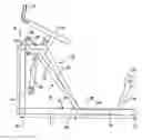
BRIEF DESCRIPTION OF THE DRAWINGSFIG. 1 is a perspective view of one embodiment of the invention;
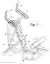
FIG. 2 is a side view of the apparatus in FIG. 1, with a side panel removed for clarity, a lower portion removed for clarity;
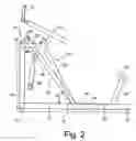
FIG. 3 is a bottom plan view of the main support frame as in FIGS. 1 and 2; and
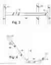
FIG. 4 is a side view of the exercising lever as in FIGS. 1 and 2.
DETAILED DESCRIPTION OF A PREFERRED EMBODIMENTConsidering first FIGS. 1 and 2, the apparatus comprises a main support frame 10 having a bottom of base member 12 a forwardly positioned upright leg 14 and a connecting leg 16 extending rearward from the top end 18 of the leg 14, at 20 and then downward and rearwardly at 22 to connect at its lower end 24 to the base member 12 at 26. Transverse members 30 and 32 are positioned at each end of the base member 12 and a further transverse member 34 extends at an intermediate position.
In the embodiment illustrated, the portions 20 and 22 comprise parallel spaced apart members while the upright leg 14 is conveniently a single member.
Positioned on the top portions 20 is a pivot 40.
Extending between the two parallel spaced apart members of portions 20 and 22 is positioned an exercise lever 42. The lever 42 has three portions; a base 44, a rear outwardly extending portion 46 and an upwardly and forwardly extending portion 48. At its upper end 50 the forwardly extending portion 48 the exercise lever is pivotally attached to the pivot 40. The base 44 of the exercise lever extends through and into a slot 52 cut in the base member 12 of the main frame.
At the upper rearward end of the portion 46 is mounted a padded leg engagement member 54.
Conveniently the two transverse members 32 and 34 are covered by platform 56, shown in FIG. 1, a slot is also formed in the platform for movement of the exercise lever 42. Side panels can also be provided connecting the upper parts of the leg 14 and leg 16 as seen at 58 in FIG. 1. These panels are not shown in FIG. 2.
Attached to an intermediate point on the leg 14 is a bracket 64 to which is connected the lower end of a pneumatic cylinder 66. At its upper end the cylinder 66 is connected to a bracket 68 on the portion 48 of exercise lever 42.
In use a person stands on the platform 56 with legs astride the exercise lever 42. Leaning forward the user supports the upper body using the two spaced support members 70 mounted at the upper end of the portion 22 of the leg 16 of the main frame. (See particularly FIG. 1). If desired two handles 72 can be provided. The user then raises one leg, rearwardly but maintaining the leg straight so that the rear of the ankle engages the padded member 54. Lifting of the member 54 causes pivoting of the exercise lever 48 about pivot 40 against resistance of the cylinder 66.
Depending upon the size of the user, dimensions, etc., can vary. However, it has been found that certain dimensions provide a generally universal apparatus. For example, the length of the main frame—dimension “A” FIG. 2—is about 50″. The height “B” is about 34″. The vertical height of the exercising lever, from base to pivot point—“C”—is about 43″.
The slot 50 is about 18″ long and is positioned about 21″ from the leg 30. The base member extends about 9″ from the rear end of the slot.
Various angles have been determined to give optimum results. Thus, the angles A and F at the junctions between base 44 and portions 46 and 48 are about 136° and 123° respectively. The angle G between the base member 12 and portion 22 of the main frame is about 56°. The support members 70 are mounted such that an axis normal to the support members extends at about 125° through the top portion 20 angle H in FIG. 2. The transverse members are conveniently made 22″ long but this is only critical from the stability concern for the apparatus.
Conveniently the various members of the frame and exercise lever, and other parts, are tubular form, and are metal, although other forms of structure can be used.
While a (pneumatic) hydraulic cylinder 60 has been shown and described, other forms of resistance member can be used. Typical operations are springs, a pulley and weight arrangement, a pneumatic cylinder, rubber or other elastic materials. Means may be provided for variably adjusting a resistance produced by the resistance member. For example, means may be provided for varying the effective overall length of the cylinder assembly 66. As an alternative one or both of the attachment positions of the cylinder to the upright leg 14 and to the exercise lever 42 can be varied.
Claims
1. An exercise apparatus comprising:
a main support frame having a base member, a forwardly positioned upright leg attached to a forward end of the base member and a connecting leg extending from a top end of said upright leg downwardly and rearwardly to connect at the bottom end through said base member;
an exercising lever including a base, a rear upwardly extending portion extending upwardly and rearwardly from a rear end of said base portion and a forward portion extending upwardly and forwardly from a front end of said base portion, said forward portion pivotally attached to said main support frame at an upper end of said upright leg of said main support frame;
a leg engaging member extending laterally at an upper end of said rear upwardly extending portion;
platform means on said main frame member for positioning of a user;
resistance means for providing a resistance against pivoting of said exercise lever by a user, said resistance means positioned between said upright leg of said main support frame and said forward portion of said exercising lever;
a support structure positioned above and attached to an upper part of said connecting leg, for support of a users upper body; and
the arrangement such that a user straddles said exercise lever, facing forward, with the upper body supported by said support structure, extending a straight leg to move a rear surface of an ankle into contact with said leg engaging member, further movement pivoting said exercise lever against said resistance means.
2. Apparatus as claimed in claim 1, said connecting leg comprising two parallel spaced apart members, said exercising lever positioned between the said spaced apart members.
3. Apparatus as claimed in claim 2, including a slot extending into said base member from the top surface, said exercising lever extending into said slot.
4. Apparatus as claimed in claim 1, including spaced laterally extending members extending transversely of said base member, to stabilize said main frame.
5. Apparatus as claimed in claim 4, including a platform supported on said laterally extending members.
6. Apparatus as claimed in claim 1, said resistance claims comprising a hydraulic cylinder.
7. Apparatus as claimed in claim 1, said support structure comprising two spaced apart parallel support members, extending in a fore and aft direction.
8. Apparatus as claimed in claim 1, including means for varying the resistance of the resistance member.
Images & Drawings included:
Sources:
- United States Patent and Trademark Office - verify current appl. status at the USPTO↗
Similar patent applications:
- » 20190009135
MOBILE EXERCISE APPARATUS CONTROLLER AND INFORMATION TRANSMISSION COLLECTION DEVICE COUPLED TO EXERCISE APPARATUS AND EXERCISE APPARATUS AND CONTROL METHOD - » 20070254778
Exercise apparatuses, components for exercise apparatuses and related methods - » 20080242520
Exercise apparatus, resistance selector for exercise apparatus and related methods - » 20090227432
Exercise apparatus, resistance selector for exercise apparatus and related methods - » 20080026922
Tension line exercise apparatus and method of exercising using a tension line exercise apparatus - » 20090280969
Tension line exercise apparatus and method of exercising using a tension line exercise apparatus - » 20140113779
Hand-held exercise apparatus and resistance mechanism for exercise apparatus - » 20080139307
Simulated Experience Apparatus, Energy Consumption Calculation Method, Squatting Motion Detection Apparatus, Exercise Assist Apparatus, Animation Method, Exercise Amount Management Apparatus, Athletic Ability Measurement Apparatus, Reflexes Ability Measurement Apparatus, And Audio-Visual System - » 20090209397
Exercise apparatus and method of use of an exercise apparatus - » 20130210576
Exercise apparatus and alphanumeric keyboard intended for such an exercise apparatus
Recent applications in this class:
- » 20240024732 2024-01-25
Hip Flexor Stretch Device - » 20230381582 2023-11-30
EXERCISE APPARATUS FOR PERFORMING A GLUTEAL BRIDGE MOVEMENT - » 20230201658 2023-06-29
GLUTE BRIDGE APPARATUS - » 20220273983 2022-09-01
Glute press exercise machine - » 20220258003 2022-08-18
Exercise apparatus for training muscles - » 20220233914 2022-07-28
PELVIS TRAINING DEVICE - » 20220080257 2022-03-17
Exercise apparatus for performing a gluteal bridge movement - » 20220001235 2022-01-06
Glute press exercise machine - » 20210322823 2021-10-21
Glute bridge apparatus - » 20210178224 2021-06-17
Exercise apparatus for strengthening the hips and associated musculature