Opening and shutting apparatus for flow control
US20050274136A1
2005-12-15
11/002,226
2004-12-03
Abstract:
An opening and shutting apparatus for a flow control to adjust a fluid flow inside a duct, especially, in which a kinematical structure is used, and so the sum of the moment acting on the knob on closing-up the inside of the duct is forced to come to zero, so that the inside of the duct can be stably closed up without special locking projection or spring, etc.
Assignee:
- HYUNDAI MOBIS CO., LTD. 67 🇰🇷 Yongin-shi, South Korea
Interested in similar patents?
Get notified when new applications in this technology area are published.
Classification:
B60H1/00857 » CPC main
Heating, cooling or ventilating [HVAC] devices; Control systems or circuits; Control members or indication devices for heating, cooling or ventilating devices; Control systems or circuits characterised by their output, for controlling particular components of the heating, cooling or ventilating installation the components being ventilating, air admitting or air distributing devices; Damper doors, e.g. position control characterised by the means connecting the initiating means, e.g. control lever, to the damper door
F24F13/1426 » CPC further
Details common to, or for air-conditioning, air-humidification, ventilation or use of air currents for screening; Air-flow control members, e.g. louvres, grilles, flaps or guide plates movable, e.g. dampers built up of tilting members, e.g. louvre characterised by actuating means
F24F2013/1473 » CPC further
Details common to, or for air-conditioning, air-humidification, ventilation or use of air currents for screening; Air-flow control members, e.g. louvres, grilles, flaps or guide plates movable, e.g. dampers built up of tilting members, e.g. louvre characterised by actuating means with cams or levers
Description
RELATED APPLICATIONSThe present disclosure relates to subject matter contained in priority Korean Application No. 10-2004-0042083, filed on Jun. 09, 2004, which is herein expressly incorporated by reference in its entirety.
BACKGROUND OF THE INVENTION1. Field of the Invention
The present invention relates to an opening and shutting apparatus for a flow control to regulate the fluid flow inside a duct, more specially to an opening and shutting apparatus for a flow control to regulate the fluid flow inside a duct, in which the sum of the moment acting on the knob comes to almost zero by applying the direction of the applied pressure force to be toward the rotary center of the knob, while the pressure applied to a damper door by fluid is transferred to a knob through a link when the duct inside is closed up.
2. Description of the Related Art
In general, an opening and shutting apparatus for a flow control is a kind of device, in which a knob is rotated and the rotary power of the knob is transferred to a damper door arranged inside duct through a link, so that the damper door can go round, and thereby opening and shutting a flow path.
If the damper door is shut by the rotation of the knob, the pressure force by the fluid is applied to the damper door. In order to withstand the pressure and to maintain the closed state, a locking notch or a spring, as shown in FIG. 1, had to be specially arranged according to Korean utility model No. 1998-038245.
If the locking notch or the spring is installed in the opening and shutting apparatus for a flow control, it has following problem that a working process comes to complicated, and disadvantageous that a smooth operation is impossible because the locking notch, etc. has an effect on the operating power of the knob, the cost is increased by the part number, and a quality problem is caused.
SUMMARY OF THE INVENTIONTo solve the above-indicated problems, it is, therefore, an object of the present invention to improve the opening and shutting apparatus for a flow control, so that the pressure of fluid can be withstood with aid of kinematical structure without locking notch or spring only when the inside of the duct is closed up, and the closed state therein be maintained.
Besides, in another aspect of the object, it is to provide a sliding groove of a bent structure, so that opening and shutting of the duct can be adjusted just by the knob rotation of a small angle.
To achieve the above object, there is provided an opening and shutting apparatus for a flow control which includes of a damper door opening and shutting the path inside the duct; a link, connected with the end of the damper door, in which a sliding groove is shaped; and a knob having a coupling projection to be connected with the sliding groove of the link; wherein a normal line of the points farthest from the rotary center of the knob among the contact points between the sliding groove and the coupling projection of the knob passes the rotary center of the knob when the duct inside is closed up, and more preferably that the sliding groove of the link has a bent shape.
BRIEF DESCRIPTION OF THE DRAWINGSThe above aspects and features of the present invention will be more apparent by describing certain embodiments of the present invention with reference to the accompanying drawings, in which:
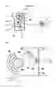
FIG. 1 illustrates an opening and shutting apparatus for a flow control using a conventional locking projection in a schematic view;
FIG. 2 illustrates a first embodiment of the opening and shuttling apparatus for a flow control according to the present invention in a schematic view; and
FIG. 3 illustrates a second embodiment of the opening and shutting apparatus for a flow control according to the present invention in a schematic view.
DETAILED DESCRIPTION OF THE PREFERRED EMBODIMENTSAn opening and shutting apparatus for a flow control according to the present invention includes a damper door 200 for opening and shutting the flow path inside a duct; a knob 300 for, formed into the duct, adjusting the damper door 200 with a rotary power, and having a coupling projection 301 thereon; and a link 400 for, being connected with the damper door 200, transferring the rotary power of the knob 300 to the damper door 200 from the point of view that the coupling projection 301 of the knob 301 is inserted into the sliding grooves 401 and 402 formed inside the link 300.
The damper door 200 opens and shuts the inside of the duct by being axis-supported at the center of the inside of the duct, and, to increase the closing effect and decrease the noise, pads 201 are formed along the circumference of the door damper 200.
The link 400 is fixed into the one side end of the damper door 200, and the damper door 200 and the link have a same rotary center. The sliding grooves 401 and 402 of the link 400, as shown FIG. 2, can have a straight form, and as shown FIG. 3, or a bent form.
Accordingly, because the rotation speed of the link caused by that of the knob 300 depends on the bent angle and form of the sliding groove of the link 400, the section requiring a fast rotation of the damper door 200 and the section requiring a slow rotation thereof can be adjusted by the shape of the sliding groove.
The knob 300 transfers the power applied from the outside to the damper door 200 through the link 400, so that the opening and the shutting of the duct inside can be adjusted. A coupling projection 301 is arranged on the knob 300, inserted into the sliding grooves 401 and 402 formed in the link 400, and transfer the rotation power of the knob 300 to the link 400.
In view of the process in which the duct inside is closed up, a user rotates the knob 300, and then the coupling projection 301 arranged on the knob 301 slides in the sliding grooves 401 and 402 of the link 400 by the rotating knob 300 and rotates the link 400. Accordingly, the rotating link 400 makes the door damper 200, which has a same rotary axis and whose end is coupled with the link, rotated around the axis.
If the duct inside, as shown FIG. 2 or 3, is closed up by the rotation of the damper door 200, the pressure of fluid is applied to the damper door 200. At this time, the power applied to the damper door 200 is transferred to the knob 300 by the link 400. At this moment, the coupling projection 301 of the knob 300 is located in the end of the sliding grooves 401 and 402 of the link 400, and then the round coupling projection 301 is surface-contacted with the end of the half-rounded sliding grooves 401 and 402. Because of the surface contact, numberless many points exist, but the points located in the farthest from the rotary center of the knob among such contact points builds up one line, and the normal line of those indicates the direction of the power which is applied to the knob by the link. In this case, the direction in which the rotary power of the link has an effect on the knob, that is, the direction 302 of the normal line makes for the rotary center 303 of the knob.
If this structure is provided, the power to make the knob 300 rotated is not applied to the knob. Namely, the sum of the moment applied to the knob comes to zero. Because there exists no rotary power, the pressure of fluid can be withstood and the closed state be maintained without a special coupling notch 1 or spring.
The effects of the present intention can be summarized as follows:
Firstly, when the pressure of fluid acting on the door damper is transferred to a coupling projection of knob, the sum of the moment applied to the knob comes to zero by means of the kinematical structure only, without special coupling projection or spring, so that the pressure of fluid can be naturally withstood and the closed state be maintained.
Secondly, the sliding groove of the link has a bent form, so that the rotating speed of the link can be changed, and accordingly, the opening and shutting speed of the damper door be adjusted. That is, the section wanting the fast rotation of the damper door and the section wanting the slow rotation thereof can be adjusted according to the bent angle of the sliding groove.
The foregoing embodiment and advantages are merely exemplary and are not to be construed as limiting the present invention. The present teaching can be readily applied to other types of apparatuses. Also, the description of the embodiments of the present invention is intended to be illustrative, and not to limit the scope of the claims, and many alternatives, modifications, and variations will be apparent to those skilled in the art.
Claims
1. An opening and shutting apparatus for a flow control, comprising:
a damper door opening and shutting a path inside a duct;
a link configured to be connected with an end of the damper door and in having a sliding groove formed therein; and
a knob having a coupling projection thereon configured to be connected with the sliding groove of the link,
wherein a line normal to a point farthest from a rotational center of the knob among contact points between the sliding groove and the coupling projection of the knob passes through the rotational center of the knob when the duct inside is closed up.
2. The opening and shutting apparatus according to claim 1, wherein the sliding groove of the link has a bent shape.
Images & Drawings included:


Sources:
- United States Patent and Trademark Office - verify current appl. status at the USPTO↗
Recent applications in this class:
- » 20240317019 2024-09-26
AIR OUTLET APPARATUS - » 20240246392 2024-07-25
RELIEF VENT FOR HEATING VENTILATION AND AIR CONDITIONING SYSTEM - » 20220266654 2022-08-25
DEVICE FOR CONTROLLING A FLAP - » 20210178857 2021-06-17
Ventilation device - » 20200009940 2020-01-09
KINEMATICS ASSEMBLY - » 20200001684 2020-01-02
Door drive device - » 20190232756 2019-08-01
Link mechanism - » 20190152291 2019-05-23
INSIDE/OUTSIDE AIR SWITCHING DEVICE - » 20190152290 2019-05-23
Air mixing damper arrangement - » 20180251010 2018-09-06
Actuator having a test mode
Recent applications for this Assignee:
- » 20080023943 2008-01-31
CUSHION OF AIR BAG APPARATUS - » 20070296186 2007-12-27
CUSHION OF AIR BAG SYSTEM - » 20070152490 2007-07-05
SEAT ASSEMBLY FOR AUTOMOBILE - » 20070139940 2007-06-21
Front end module carrier for vehicle - » 20070138779 2007-06-21
Passenger air bag module - » 20070138777 2007-06-21
AIR BAG SYSTEM - » 20070138773 2007-06-21
Cushion of air bag module - » 20070120346 2007-05-31
Air bag module - » 20070118265 2007-05-24
OCCUPANT CLASSIFYING SYSTEM AND METHOD OF VEHICLE - » 20070061102 2007-03-15
Method for classifying occupant weight of vehicle