Micro heat spreader
US20060002091A1
2006-01-05
10/983,596
2004-11-09
Abstract:
A micro heat spreader having an inside vacuum chamber, a bottom recess in the bottom wall thereof, a filling hole formed in the bottom recess in fluid communication with the inside vacuum chamber, a fluid filled into the inside vacuum chamber, and a bronze stopper fastened to the bottom recess to seal the filling hole and maintained in flush with the bottom wall.
Interested in similar patents?
Get notified when new applications in this technology area are published.
Classification:
H01L23/42 » CPC main
Details of semiconductor or other solid state devices; Arrangements for cooling, heating, ventilating or temperature compensation ; Temperature sensing arrangements Fillings or auxiliary members in containers or encapsulations selected or arranged to facilitate heating or cooling
H01L2924/0002 » CPC further
Indexing scheme for arrangements or methods for connecting or disconnecting semiconductor or solid-state bodies as covered by; Technical content checked by a classifier Not covered by any one of groups , and
H01L2924/00 » CPC further
Indexing scheme for arrangements or methods for connecting or disconnecting semiconductor or solid-state bodies as covered by
H05K7/20 IPC
Constructional details common to different types of electric apparatus Modifications to facilitate cooling, ventilating, or heating
H05K7/20 IPC
Constructional details common to different types of electric apparatus Modifications to facilitate cooling, ventilating, or heating
Description
BACKGROUND OF THE INVENTION1. Field of the Invention
The present invention relates to a micro heat spreader for use with a semiconductor chip to spread heat.
2. Description of the Related Art:
Following fast development of nanotechnology, the number of transistors in an IC chip has been increased in the manner of geometric progression. A high-density IC chip provides a strong operating power. However, a high-density IC chip releases much heat during operation. Various heat dissipation devices have been disclosed to dissipate heat from a semiconductor chip. A micro heat spreader or the so-called flat thermal tube is one of the most efficient heat dissipation devices for this purpose. Conventional micro heat spreaders commonly comprise a flat panel, which defines therein a vacuum chamber, and a fluid filled in the vacuum chamber for spreading heat energy. A regular micro heat spreader further comprises a filling hole in one side wall in fluid communication with the vacuum chamber. During fabrication, a copper tube is inserted into the filling hole for drawing air out of the vacuum chamber. After filling of the fluid into the vacuum chamber, the copper tube is properly cut and sealed by arc welding. After arc welding, the welded outer end of the copper tube protrudes over the outside wall of the micro heat spreader at a distance about 5 mm. The protruded outer end of the copper tube hinders the installation of the micro heat spreader in an electronic package.
There is known another design of micro heat spreader, which has the filling hole formed in the bottom wall. After arc welding to seal the outer end of the copper tube that is inserted into the filling hole for drawing air out of the vacuum chamber, the protruded outer end of the copper tube hinders close attachment of the micro heat spreader to a semiconductor chip, thereby lowering the heat spreading efficiency of the micro heat spreader.
SUMMARY OF THE INVENTIONThe present invention has been accomplished under the circumstances in view. It is one object of the present invention to provide a micro heat spreader, which has a flat bottom wall that can be closely attached to a semiconductor chip close. It is another object of the present invention to provide a micro heat spreader, which effectively spreads heat during operation of the semiconductor chip to which the micro heat spreader is attached. To achieve these and other objects of the present invention, the micro heat spreader comprises an inside vacuum chamber, a bottom recess in the bottom wall thereof, a filling hole formed in the bottom recess in fluid communication with the inside vacuum chamber, a fluid filled into the inside vacuum chamber, and a bronze stopper fastened to the bottom recess to seal the filling hole and maintained in flush with the bottom wall. Alternatively, a metal tube may be used and mounted in the filling hole to substitute for the bronze stopper. After filling of the fluid into the vacuum chamber, the outer end of the metal tube is properly cut and hammered down to close the passage of the filling hole, keeping the closed outer end of the metal tube inside the bottom recess of the micro heat spreader without hindering the installation of the micro heat spreader in a semiconductor chip.
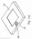
BRIEF DESCRIPTION OF THE DRAWINGSFIG. 1(a) is an oblique bottom elevation of a micro heat spreader according to the first embodiment of the present invention.
FIG. 1(b) is a side view in section of the micro heat spreader according to the first embodiment of the present invention.
FIG. 2(a) is an oblique bottom elevation of a micro heat spreader according to the second embodiment of the present invention.
FIG. 2(b) is a side view in section of the micro heat spreader according to the second embodiment of the present invention.
DETAILED DESCRIPTION OF THE PREFERRED EMBODIMENTReferring to FIGS. 1(a) and 1(b), a micro heat spreader 20 in accordance with the first embodiment of the present invention is shown comprising an inside vacuum chamber 22, a circular recess 26 formed in the bottom wall, a filling hole 24 formed in the circular recess 26 in fluid communication with the inside vacuum chamber 22, and a stopper 40 fitted into the circular recess 26 to seal the filling hole 24.
During fabrication of the micro heat spreader 20, vacuum pump means (not shown) is attached to the circular recess 25 and the filling hole 24 to draw air out of the inside vacuum chamber 22. After the inside vacuum chamber 22 has been changed into a vacuum status, a fluid or water is filled through the filling hole 24 into the inside vacuum chamber 22, and then the stopper 40 is fastened to the circular recess 26 to seal the filling hole 24. According to this first embodiment, the stopper 40 is a bronze member spot-welded to the circular recess 25 of the micro heat spreader 20 and maintained in flush with the bottom wall of the micro heat spreader 20. FIG. 1(b) shows the micro heat spreader 20 attached to a semiconductor chip 44. Because the stopper 40 is kept in flush with the bottom wall of the micro heat spreader 20, the micro heat spreader 20 can be maintained closely attached to the semiconductor chip 44. Further, the micro heat spreader 20 is fixedly secured to the semiconductor chip 44 by an adhesive by means of the application of an adhesive machine.
FIGS. 2(a) and 2(b) show a micro heat spreader constructed according to a second embodiment of the present invention. According to this embodiment, the micro heat spreader 20 comprises an inside vacuum chamber 22, a bottom recess 28 formed in the bottom wall, a filling hole 24 formed in the bottom recess 28 in fluid communication with the inside vacuum chamber 22, and a copper tube 42 inserted into the filling hole 24. The bottom recess 28 has a substantially U-shaped profile. The protruding outer end of the copper tube 42 is properly cut and hammered down to close the passage of the filling hole 24 after the inside vacuum chamber 22 has been processed into a vacuum status and filled with a fluid. After fabrication, the closed outer end of the copper tube 42 is kept inside the bottom recess 28 and spaced from the bottom wall of the micro heat spreader 20 at a distance. Therefore, the closed outer end of the copper tube 42 does not hinder the installation of the micro heat spreader 20 in a semiconductor chip 44.
A prototype of micro heat spreader has been constructed with the features of FIGS. 1 and 2. The micro heat spreader functions smoothly to provide all of the features discussed earlier.
Although particular embodiment of the invention have been described in detail for purposes of illustration, various modifications and enhancements may be made without departing from the spirit and scope of the invention.
Claims
What the invention claimed is:1. A micro heat spreader comprising an inside vacuum chamber, a recess in an outside wall thereof, and a filling hole formed in said recess in fluid communication with said inside vacuum chamber.
2. The micro heat spreader as claimed in claim 1, further comprising a fluid filled in said inside vacuum chamber.
3. The micro heat spreader as claimed in claim 1, wherein said recess has a circular shape.
4. The micro heat spreader as claimed in claim 1, wherein said recess has a U-shaped profile.
5. The micro heat spreader as claimed in claim 1, further comprising a filling tube mounted in said filling hole, said filling hole having an inner end extended to said inside vacuum chamber and an outer end extended to said recess.
6. The micro heat spreader as claimed in claim 5, wherein said filling tube is a metal tube.
7. The micro heat spreader as claimed in claim 6, wherein said metal tube is made of a copper alloy.
8. The micro heat spreader as claimed in claim 1, further comprising a stopper fastened to said recess to seal said filling hole.
9. The micro heat spreader as claimed in claim 8, wherein said stopper is made of a metal material.
10. The micro heat spreader as claimed in claim 9, wherein said metal material is selected from one of the material group including nickel, bronze, and their alloys.
11. The micro heat spreader as claimed in claim 1, wherein said outside wall is at a bottom side of the micro heat spreader to be attached to a semiconductor chip.
Images & Drawings included:


Sources:
- United States Patent and Trademark Office - verify current appl. status at the USPTO↗
Similar patent applications:
Recent applications in this class:
- » 20250149402 2025-05-08
SEMICONDUCTOR PACKAGE STRUCTURE - » 20250140643 2025-05-01
PACKAGE STRUCTURE - » 20250105092 2025-03-27
POWER CONVERSION APPARATUS - » 20250087555 2025-03-13
DIE STRUCTURES AND METHODS OF FORMING THE SAME - » 20250062186 2025-02-20
SEMICONDUCTOR PACKAGE - » 20250046674 2025-02-06
Recess Island Lid Design for TIM Delamination Risk Mitigation - » 20250006587 2025-01-02
SEMICONDUCTOR PACKAGE AND METHOD - » 20240421034 2024-12-19
SEMICONDUCTOR PACKAGE - » 20240413052 2024-12-12
Heat Dissipation Structures - » 20240379496 2024-11-14
PACKAGE ASSEMBLY INCLUDING LIQUID ALLOY THERMAL INTERFACE MATERIAL (TIM) AND SEAL RING AROUND THE LIQUID ALLOY TIM AND METHODS OF FORMING THE SAME