Structure of a mask having a mask arc
US20060010550A1
2006-01-19
10/893,314
2004-07-19
Abstract:
A mask having a mask arc and a mask body is disclosed. The mask arc includes a lower arc and an elastic strip, the two side ends of the lower arc are mounted with the elastic strip and an engaging slot is located between the side ends and the external sides of the two ends of the lower arc are provided with a protruded seat and the surface of the protruded seat has radially distributed protruded strips and a through hole is formed on the center of the protruded seat; the mask is formed as one unit and the upper edge of the mask is horizontally extended to form a blocking plate and the two ends of the inner side of the mask at the upper side are provided with the protruded block corresponding to the protruded seat at the lower arc, and the surface of the protruded block is provided with radially arranged recess and the center of the protruded block is provided with a through opening.
Interested in similar patents?
Get notified when new applications in this technology area are published.
Classification:
A42B3/225 » CPC main
Helmets; Helmet covers ; Other protective head coverings; Parts, details or accessories of helmets; Face protection devices; Visors with full face protection, e.g. for industrial safety applications
A61F9/061 » CPC further
Methods or devices for treatment of the eyes; Devices for putting-in contact lenses; Devices to correct squinting; Apparatus to guide the blind; Protective devices for the eyes, carried on the body or in the hand; Eye-masks ; Devices to be worn on the face, not intended for looking through; Eye-pads for sunbathing; Masks, shields or hoods for welders with movable shutters, e.g. filter discs; Actuating means therefor
A41D13/00 IPC
Professional, industrial or sporting protective garments, e.g. surgeons' gowns or garments protecting against blows or punches
Description
BACKGROUND OF THE INVENTION(a) Technical Field of the Invention
The present invention relates to a combination structure of a mask body.
(b) Description of the Prior Art
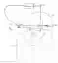
A safety helmet for use in welding operation is mounted with a mask. At the two lateral sides of the mask 10 and the working helmet 20 are through holes, and a rotating button 30 passes through the holes and is fastened with a screw nut so that a pivot connection is obtained (FIG. 1). In order to have a bigger masking area, the front portion of the mask 10 is connected to an arch-shaped extension 101. In practice, this extension 101 does not contribute any usefulness in the course of a welding operation. The mask 10 is provided at the rear portion of the head, as shown in FIG. 2, and therefore both of the hands have to unscrew the button 30 and then, lift the extension 101. After the welding process, the extension 101 has to be restored with both hands and the button 30 is tightened. However, in the course of welding, the working helmet 20 has to be taken down and the mask 10 has to be aligned with the mounting position, as shown in FIG. 3. If the user needs to lift up the mask 10 while welding, the processes of loosening the button, and tightening the button 30 are repeating. The repeating process will cause the mask 10 to disconnect from the working helmet 20 after a period of use. The drawbacks of the structure are as follows:
-
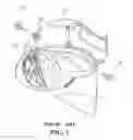
- (1) When the mask is not used in welding operation, it is positioned at the rear portion of the head. The bottom end of the mask may hook onto the neck of the wearer (shown in FIG. 2). If the mask is lifted upward, the weight at the rear portion of the head is heavy. This is uncomfortable to the wearer.
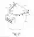
- (2) In the course of welding operation, it is laborious to mount the mask and to disconnect after use. This is very inconvenient to the user (FIG. 3).
- (3) The lens of the mask is too close to the mouth and noise of the wearer, fog may occur at the lens, and therefore, the cleaning of the lens is needed. This is again laborious and inconvenient.
- (4) The complicated structure causes an increase in production cost.
- (5) Through holes have to be provided to the working helmet. Therefore, the mask is not applicable to all types of helmets.
- (6) The uplifting and lowering of the mask together with the adjustment of nut is not convenient.
In view of the above drawbacks, the present invention provides a structure of a mask having a mask arc.
SUMMARY OF THE INVENTIONAccordingly, it is an object of the present invention to provide a mask having a mask arc characterized in that the mask arc includes a lower arc and an elastic strip, the two side ends of the lower arc are mounted with the elastic strip and an engaging slot is located between the side ends and the external sides of the two ends of the lower arc are provided with a protruded seat and the surface of the protruded seat is radially distributed protruded strips and a through hole is formed on the center of the protruded seat; the mask is formed as one unit and the upper edge of the mask is horizontally extended to form a blocking plate and the two ends of the inner side of the mask at the upper side are provided with the protruded block corresponding to the protruded seat at the lower arc, and the surface of the protruded block is provided with radially arranged recess and the center of the protruded block is provided with a through opening.
Yet another object of the present invention is to provide a structure of a mask having a mask arc, wherein the mask arc and the mask body are respectively connected by the protruded seat and the protruded block and the radially arranged protruded stripes are engaged with the recess, and a rivet is used to pass through the through hole and the through opening so that the rivet is used as a pivot shaft which allows a turning.
Still another object of the present invention is to provide a structure of a mask having a mask arc, wherein the mask body is provided with a window and the external side of the window is a rotating window cover.
The foregoing object and summary provide only a brief introduction to the present invention. To fully appreciate these and other objects of the present invention as well as the invention itself, all of which will become apparent to those skilled in the art, the following detailed description of the invention and the claims should be read in conjunction with the accompanying drawings. Throughout the specification and drawings identical reference numerals refer to identical or similar parts.
Many other advantages and features of the present invention will become manifest to those versed in the art upon making reference to the detailed description and the accompanying sheets of drawings in which a preferred structural embodiment incorporating the principles of the present invention is shown by way of illustrative example.
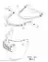
BRIEF DESCRIPTION OF THE DRAWINGSFIG. 1 is a perspective view of a conventional mask.
FIG. 2 is a schematic view showing a conventional mask being worn prior to a welding operation.
FIG. 3 is a schematic view showing a conventional mask being worn in the course of a welding operation.
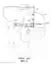
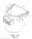
FIG. 4 is an exploded perspective view of a second conventional mask with a mask arc.
FIG. 5 is a perspective view of FIG. 4.
FIG. 6 is an elevation view of FIG. 5.
FIG. 7 is an exploded perspective view of a third conventional mask with a mask arc.
FIG. 8 is a perspective view of FIG. 7.
FIG. 9 is an elevational view of FIG. 8.
FIG. 10 is a perspective exploded view of the mask with a mask arc in accordance with the present invention.
FIG. 11 is an elevational view showing the lifting of the window mask of the mask of the present invention.
FIG. 12 is a perspective view of the present invention.
FIG. 13 is an elevational view of the present invention.
DETAILED DESCRIPTION OF THE PREFERRED EMBODIMENTSThe following descriptions are of exemplary embodiments only, and are not intended to limit the scope, applicability or configuration of the invention in any way. Rather, the following description provides a convenient illustration for implementing exemplary embodiments of the invention. Various changes to the described embodiments may be made in the function and arrangement of the elements described without departing from the scope of the invention as set forth in the appended claims.
Referring to FIG. 10, there is shown a combination structure of a mask body 2 and a mask arc 1. The mask arc 1 includes a lower arc 11 and an elastic strip 12. The elastic strip 12 is connected to the two lateral ends of the lower arc 11, and the lower arc 11, between two lateral ends, is provided with an engaging slot 111 for engaging with the front end portion of a working helmet h (FIG. 13). The elastic stripe 12 is elastically mounted to the rear end portion of the working helmet h. The outer side of the two end of the lower arc 11 is provided with a protruded seat 112 having a surface with radially distributed stripes 113. The center of the protruded seat 112 is a through hole 114.
The mask body 2 is formed as a unit and a blocking plate 21 is formed from horizontally extension of the mask body 2. The two ends of the inner side of the mask body 2, corresponding to the protruded seat 112, are provided with a protruded block 22. The surface of the protruded block 22 has a radial shape recess 221. The center of the protruded block 22 is a through hole 222. Further, if the mask is used for welding, a window 23 is provided to the mask body 2. The external side of the window 23 can be provided with a lifting window (as shown in FIGS. 10, 11).
In combination, the lower arc 11 of the mask arc 1 is closely mounted to the upper side of the inner lateral side of the mask body 2 so that the mask arc 1, the mask body 2 are connected respectively with the protruded seat 112 and the protruded block 22. The radial protruded stripes 113 and in combination with the radial shape recess 221. Rivet 3 is used to mount the mask arc 1, the mask body 2 via the through hole 114 and 222 (as shown in FIG. 12). The rivet area is a pivot for the mask arc 1 and the mask body 2, as shown in FIG. 13. After the lifting of the mask body, the protruded stripe 113 is at the position of the recess 221 to provide adjustment of uplifting angle for the mask body 2. The uplifting of the mask arc 1 is blocked by the blocking plate 21, i.e., the lowering of the mask body 2 makes use of the blocking plate 21 to position at the upper side of the lower arc. As shown in FIG. 10, a pad 31 can be mounted to the rivet 3.
In accordance with the present invention, the mask body 2 is provided with a blocking plate 21 and protruded block 22, radial recess 221 for direct connection with the lower arc 11 of the mask arc. Therefore, the process of fabrication becomes simple and the cost of product is lowered. Further, there is no disengagement between the mask arc 1 and the mask body 2 and therefore the structure is durable and can be used for an extended period of time.
It will be understood that each of the elements described above, or two or more together may also find a useful application in other types of methods differing from the type described above.
While certain novel features of this invention have been shown and described and are pointed out in the annexed claim, it is not intended to be limited to the details above, since it will be understood that various omissions, modifications, substitutions and changes in the forms and details of the device illustrated and in its operation can be made by those skilled in the art without departing in any way from the spirit of the present invention.
Claims
I claim:1. A mask having a mask arc characterized in that the mask arc includes a lower arc and an elastic strip, the two side ends of the lower arc are mounted with the elastic strip and an engaging slot is located between the side ends and the external sides of the two ends of the lower arc are provided with a protruded seat and the surface of the protruded seat has radially distributed protruded strips and a through hole is formed on the center of the protruded seat; the mask is formed as one unit and the upper edge of the mask is horizontally extended to form a blocking plate and the two ends of the inner side of the mask at the upper side are provided with the protruded block corresponding to the protruded seat at the lower arc, and the surface of the protruded block is provided with radially arranged recess and the center of the protruded block is provided with a through opening.
2. The mask having a mask arc of claim 1, wherein the mask arc and the mask body are respectively connected by the protruded seat and the protruded block and the radially arranged protruded stripes are engaged with the recess, and a rivet is used to pass through the through hole and the through opening so that the rivet is used as a pivot shaft which allows a turning.
3. The mask having a mask arc of claim 1, wherein the mask body is provided with a window and the external side of the window is a rotating window cover.
Images & Drawings included:


Sources:
- United States Patent and Trademark Office - verify current appl. status at the USPTO↗
Recent applications in this class:
- » 20250000196 2025-01-02
REINFORCED FACE PROTECTION ACCESSORIES FOR HARD HATS - » 20240268503 2024-08-15
Face Shield with Debris/Dust Control - » 20240114988 2024-04-11
Surgical personal protection apparatus - » 20230292876 2023-09-21
Surgical personal protection apparatus - » 20230121536 2023-04-20
VISOR FOR FASTENING TO A CAP OR A HEADBAND OR A CLIP - » 20220279889 2022-09-08
Upper garment worn during overhead welding - » 20220273065 2022-09-01
SENSOR ASSISTED HEAD MOUNTED DISPLAYS FOR WELDING - » 20220095736 2022-03-31
FACE SHIELD WITH POWERED AIR PURIFYING RESPIRATOR AND METHODS OF USE - » 20210386155 2021-12-16
Face shield for baseball cap - » 20210345721 2021-11-11
Non-Impact Construction Face Shield