Method of noise factor computation for chip equalizer in spread spectrum receiver
US20060018367A1
2006-01-26
11/183,967
2005-07-19
✅ Patent granted
US 7,577,187 B2
2009-08-18
-
-
Chieh M. Fan | Eva Puente
2027-02-23
Abstract:
A method of noise factor computation for a chip equalizer in a spread spectrum receiver, the method including the steps of: computing channel and noise variance estimates for multiple resolvable fading paths of chip signals received at the spread spectrum receiver; computing the sum of power of the channel estimates; estimating the chip energy of the chip signals; and computing the noise factor from the chip energy estimate, channel and noise variance estimates, sum of power of the channel estimates, and spreading factor of the pilot signal.
Assignee:
- NEC Corporation 20,055 🇯🇵 Tokyo, Japan
Interested in similar patents?
Get notified when new applications in this technology area are published.
Classification:
H04B1/69 IPC
Details of transmission systems, not covered by a single one of groups - ; Details of transmission systems not characterised by the medium used for transmission Spread spectrum techniques
H04L25/0206 » CPC main
Baseband systems; Details ; arrangements for supplying electrical power along data transmission lines; Channel estimation of multiple channels of each channel individually
H04L1/20 » CPC further
Arrangements for detecting or preventing errors in the information received using signal quality detector
H04L25/03133 » CPC further
Baseband systems; Details ; arrangements for supplying electrical power along data transmission lines; Shaping networks in transmitter or receiver, e.g. adaptive shaping networks; Arrangements for removing intersymbol interference operating in the time domain non-adaptive, i.e. not adjustable, manually adjustable, or adjustable only during the reception of special signals with a non-recursive structure
H04B1/7115 » CPC further
Details of transmission systems, not covered by a single one of groups - ; Details of transmission systems not characterised by the medium used for transmission; Spread spectrum techniques using direct sequence modulation; Interference-related aspects the interference being multi-path interference Constructive combining of multi-path signals, i.e. RAKE receivers
H04B1/707 IPC
Details of transmission systems, not covered by a single one of groups - ; Details of transmission systems not characterised by the medium used for transmission; Spread spectrum techniques using direct sequence modulation
H04B1/713 IPC
Details of transmission systems, not covered by a single one of groups - ; Details of transmission systems not characterised by the medium used for transmission; Spread spectrum techniques using frequency hopping
Description
BACKGROUND OF THE INVENTION1. Field of the Invention
The present invention relates generally to spread spectrum receivers, and in particular to methods of optimizing the equalization of a spread spectrum signal transmitted through multiple resolvable fading paths channel. The present invention is suitable for use in applications involving W-CDMA transmission techniques, and it will be convenient to describe the invention in relation to that exemplary application.
2. Description of the Related Art
In W-CDMA communication systems, multi code signals at the transmitter are orthogonal to each other. However, this orthogonality is lost as the signals propagate through a multipath fading channel. A chip equalizer is employed in the W-CDMA receiver as a means to restore the orthogonality of the signal, and thereby improve the receiver performance.
Typically, chip equalizers are implemented as a Finite Impulse Response (FIR) filter. The chip equalizer tries to compensate for the multipath interference by inverting the channel. A known method for computing optimal chip equalizer filter coefficients using a direct inversion matrix method involves estimation of the matrix G from the expression G=HHH+βI, where HHH is the channel correlation matrix, I is identity matrix, and β is the scalar noise factor in a W-CDMA system.
The method for channel estimation to obtain the channel correlation matrix is usually straight forward, and can be estimated based on the common pilot signal in W-CDMA systems. However, to date there has been limited or no consideration of a optimal method of computing an estimate of the scalar noise factor in the W-CDMA system. A chip equalizer that only uses knowledge of channel estimation and does not take into account noise variance results in sub optimal performance compared to a receiver that takes both factors into account.
SUMMARY OF THE INVENTIONIn view of the above, it is an object of the present invention to provide a method of equalizing the received chip signal distorted by multiple paths that ameliorates or overcomes one or more disadvantages of the prior art.
It is another object of the present invention to provide a method of noise factor computation for a chip equalizer in a spread spectrum receiver that optimized the equalization of the received chip signal.
It is still another object of the present invention to provide a method of noise factor computation for a chip equalizer in a spread spectrum receiver that was simple and practical to implement.
According to a first aspect of the present invention, there is provided a method of computing a noise factor for use in a chip equalizer making up a spread spectrum receiver, the method including the steps of:
computing channel and noise variance estimates for multiple resolvable fading paths of chip signals received at the spread spectrum receiver;
computing a sum of power of the channel estimates;
estimating chip energy of the chip signals; and
computing the noise factor from the chip energy estimate, the channel and noise variance estimates, the sum of power of the channel estimates, and spreading factor of a pilot signal.
In the foregoing first aspect, the step of computing channel and noise variance estimates may be carried out by using a despread pilot signal corresponding to each fading path.
Also, the step of computing the sum {circumflex over (P)} of power of the channel estimates may be carried out in accordance with the expression (1): P ^ = ∑ i = 1 L h ^ t 2 ( 1 )
where ĥl is the channel estimate of I-th fading path.
Furthermore, the step of computing the noise factor is preferably carried out by selecting the channel and noise variance estimates from the fading path having the greatest power.
Still furthermore, the step of selecting the channel ĥm and noise variance σm2 estimates from the fading path having the greatest power may be carried out in accordance with the expression (2): m = arg [ max { h ^ t 2 } ] ( 2 )
where m is the index of the fading path having the greatest power and ĥl is the channel estimate of I-th fading path.
In addition, the step of computing the noise factor β may be carried out in accordance with the expression (3): β = E ^ c h ^ m 2 E ^ c - SF σ m 2 - P ^ ( 3 )
where Êc is the estimated chip energy of the chip signals, ĥm is the channel estimate of the fading path having the strongest power, σm2 is the noise variance estimate of the fading path having the strongest power, SF is the spreading factor of the pilot signal received at the spread spectrum receiver and {circumflex over (P)} is sum of power of the channel estimates.
According to a second aspect of the present invention, there is provided a method of determining filer coefficients for used in a chip equalizer FIR (Finite Impulse Response) filter making up a spread spectrum receiver, the method including:
computing channel and noise variance estimates for multiple resolvable fading paths of chip signals received at the spread spectrum receiver;
computing a sum of power of the channel estimates;
estimating chip energy of the chip signals;
computing a scalar noise factor from the chip energy estimate, the channel and noise variance estimates, the sum of power of the channel estimates, and spreading factor of a pilot signal;
constructing a matrix G according to expression (4):
G=HHH+βI (4)
where HHH is a channel correlation matrix, I is identity matrix, and β is the scalar noise factor; and
calculating the filter coefficients based on the matrix G.
According to a third aspect of the present invention, there is provided a chip equalizer for use in a spread spectrum receiver, including one or more computational blocks for implementing at least one of the above-described methods.
BRIEF DESCRIPTION OF THE DRAWINGSThe above and other objects, advantages, and features of the present invention will be more apparent from the following description taken in conjunction with the accompanying drawings in which:
FIG. 1 is a schematic diagram of a spread spectrum receiver according to a preferable embodiment of the present invention; and
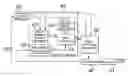
FIG. 2 is a schematic diagram of a chip equalizer forming part of a despreader block making up the spread spectrum receiver shown in FIG. 1.
DETAILED DESCRIPTION OF THE PREFERRED EMBODIMENTSThe following description refers in more detail to the various features of the invention. In order to facilitate an understanding of the invention, reference is made in the description to the accompanying drawings where the method of noise factor computation for a chip equalizer in a spread spectrum receiver is illustrated in a preferred embodiment. It is to be understood however that the invention is not limited to the preferred embodiment illustrated in the drawings.
Referring now to FIG. 1, there is shown generally a spread spectrum receiver 10 including an antenna 12 for receiving spread spectrum signals, a demodulator 14 for demodulating the spread spectrum signals received at the antenna 12, and an analogue to digital converter 16 for digitizing the demodulated signals. The spread spectrum receiver 10 uses coherent demodulation to despread the demodulated signal using a locally generated code sequence from a code generator 20 in conjunction with a despreader 18. To be able to perform the despreading operation, the spread spectrum receiver 10 must not only know the channelization code sequence used to spread the signal, but the codes of the received signal and the locally generated code must be synchronized. The code synchronization/tracking block 22 performs this operation. After despreading, data symbols are demodulated and channel decoded in a data modulation and channel coding block 24 to obtain information data.
The despreader block 18 in a conventional rake receiver consists of a number of de-spread block, each for receiving a different multipath signal. In each finger, the received signal is correlated by a spreading code, which is time aligned with the delay of the multipath signal. For each multipath, the despreaded signal is then multiplied (weighted) with conjugative of channel estimate and coherently summed by RAKE combine to form the output signal.
FIG. 2 shows despreader block 18 where the chip equalization function is performed and various computational blocks of the despreader block 18. The main function of the chip equalizer is to estimate coefficient for used by FIR filter 40 to filter the input signal and restore the orthogonality of the multicode signals. The output data of one code signal is then performed by de-spread block 41. In case of multicode signal reception, the output of FIR filter 40 is fed to multiple de-spread blocks 41 to form output data of multicode accordingly. To estimate the FIR filter coefficients, a multipath channel estimation block 42, a noise factor calculation block 44 and a coefficients calculation block 46 are needed.
The multipath channel estimation block 42 acts to compute channel and noise variance estimates for multiple resolvable fading paths of chip signals received at the spread spectrum receiver. The block 42 derives a channel estimate ĥl of I-th fading path by averaging a number of despreaded pilot symbols of that path according to expression (5):
h
^
t
=
1
K
×
∑
K
p
(
k
)
*
×
y
l
(
k
)
(
5
)
where p(k)* is conjugative of pilot symbol and |p(k)|=1, K is number of pilot symbols used for estimation, yl(k) is despreaded pilot symbol of I-th path.
The unbiased estimate of noise variance {circumflex over (σ)}l2 at the output of I-th despreader is computed by the multipath estimation block 42 according to expression (6): σ ^ l 2 ≈ K K - 1 ( 1 K ∑ K y l ( k ) 2 - h ^ l 2 ) ( 6 )
The noise factor calculation block 44 includes a strongest channel estimator block 48, a channel power calculation block 50, a chip energy estimation block 52 and a scalar noise factor calculation block 54. To estimate the scalar noise factor β based on statistics of I-th path, the following considerations have been taken into account in the design of the chip equalizers. Firstly, the average received chip energy Echip can be obtained from expression (7)
E
chip
=
E
[
r
(
m
)
2
]
≈
1
M
∑
M
r
(
m
)
2
(
7
)
where M is number of chips used in estimation and r(m) is a chip.
Secondly, the sum {circumflex over (P)} of power of channel estimates and the index m of the fading path with strongest channel estimate power can be calculated from expressions (8) and (9):
P
^
=
∑
l
=
1
L
h
^
l
2
(
8
)
m
=
arg
[
max
{
h
^
l
2
}
]
(
9
)
where ĥl is the channel estimate of I-th fading path.
Finally, the noise factor estimate {circumflex over (β)} can be estimated by using expression (10):
β
^
=
E
^
chip
h
^
m
21
E
^
chip
-
SF
σ
^
m
2
-
P
^
(
10
)
where SF is the of the spreading factor of the pilot signal received at the spread spectrum receiver.
Accordingly, the multipath channel estimation block 42 of the chip equalizer computes a channel estimate ĥl and a noise variance estimate {circumflex over (σ)}l2 according to above-referenced expressions 1 and 2. The channel estimates and noise variance estimates for each of the multiple resolvable fading paths of chip signals are provided to the channel power calculation block 50, where the sum {circumflex over (P)} of power of the channel estimates is readily obtained from the channel estimates ĥl. The sum of power of channel estimates is then provided to the beta calculation block 54. The chip energy estimation block 52 derives the estimated chip energy Êchip from the input I/Q chip samples in accordance with expression 3.
It is preferable that the noise factor is computed by selecting the channel and noise variance estimates from the fading path having the greatest power. In this regard, the strongest channel estimate block 48 acts to derive the channel and noise variance estimates ĥm and {circumflex over (σ)}m2 from the fading path having the greatest power.
The channel ĥm and noise variance σm2 estimates are then provided to the scalar noise factor calculation block 54, which then uses the chip energy estimate, channel and noise variance estimate of the strongest fading path, the sum of the power of the channel estimates and the spreading factor of the pilot signal to derive an estimate of the noise factor for use in calculating the filter coefficients.
In the filter coefficients calculation block 46, the gain matrix G=HHH+βI is constructed in order to calculate the filter coefficients of the FIR filter 40, where HHH is the channel correlation matrix, I is identity matrix, and β is the scalar noise factor in a W-CDMA system.
The various computational blocks of the chip equalizer shown in FIG. 2, as well as other elements of the spread spectrum receiver shown in FIG. 1, may be realized using digital signal processing techniques.
It is apparent that the present invention is not limited to the method of noise factor computation for a chip equalizer according to the above embodiment but may be changed and modified without departing from the scope and spirit of the invention.
Claims
1. A method of computing a noise factor for a chip equalizer in a spread spectrum receiver, the method comprising the steps of:
computing channel and noise variance estimates for multiple resolvable fading paths of chip signals received at said spread spectrum receiver;
computing a sum of power of the channel estimates;
estimating chip energy of the chip signals; and
computing the noise factor from the chip energy estimate, the channel and noise variance estimates, the sum of power of the channel estimates, and spreading factor of a pilot signal.
2. The method according to claim 1, wherein the step of computing the channel and noise variance estimates is carried out by using a despread pilot signal corresponding to each fading path.
3. The method according to claim 1, wherein the step of computing the sum {circumflex over (P)} of power of the channel estimates is carried out in accordance with expression (1):
P ^ = ∑ i = 1 L h ^ t 2 ( 1 )
where ĥl is the channel estimate of I-th fading path.
4. The method according to claim 1, wherein the step of comprising the noise factor is carried out by selecting the channel and noise variance estimates from the fading path having greatest power.
5. The method according to claim 4, wherein the step of selecting the channel ĥm and noise variance σm2 estimates from the fading path having the greatest power is carried out in accordance with expression (2):
m = arg [ max { h ^ t 2 } ] ( 2 )
where m is an index of the fading path having the greatest power and ĥl is the channel estimate of I-th fading path.
6. The method according to claim 5, wherein the step of computing the noise factor β is carried out in accordance with expression (3):
β = E ^ c h ^ m 2 E ^ c - SF σ m 2 - P ~ . ( 3 )
where Êc is the estimated chip energy of the chip signals, ĥm the channel estimate of the fading path having the strongest power, σm2 is the noise variance estimate of the fading path having the strongest power, SF is the spreading factor of the pilot signal received at said spread spectrum receiver and {circumflex over (P)} is sum of power of the channel estimates.
7. A method of determining filter coefficients for use in a chip equalizer (FIR) Finite Impulse Response) filter making up a spread spectrum receiver, the method comprising:
computing channel and noise variance estimates for multiple resolvable fading paths of chip signals received at said spread spectrum receiver;
computing a sum of power of the channel estimates;
estimating chip energy of the chip signals;
computing a scalar noise factor from the chip energy estimates, the channel and noise variance estimates, the sum of power of the channel estimates, and spreading factor of a pilot signal;
constructing a matrix G according to expression (4);
G=HHH+βI (4)
where HHH is a channel correlation matrix, I is identity matrix, and β is the scalar noise factor; and
calculating the filter coefficients based on the matrix G.
8. A chip equalizer for use in a spread spectrum receiver, comprising one or more computational blocks for implementing a method according to claim 1.
9. A chip equalizer for use in a spread spectrum receiver, comprising one or more computational blocks for implementing a method according to claim 2.
10. A chip equalizer for use in a spread spectrum receiver, comprising one or more computational blocks for implementing a method according to claim 3.
11. A chip equalizer for use in a spread spectrum receiver, comprising one or more computational blocks for implementing a method according to claim 4.
12. A chip equalizer for use in a spread spectrum receiver, comprising one or more computational blocks for implementing a method according to claim 5.
13. A chip equalizer for use in a spread spectrum receiver, comprising one or more computational blocks for implementing a method according to claim 6.
Images & Drawings included:


Sources:
- United States Patent and Trademark Office - verify current appl. status at the USPTO↗
Recent applications in this class:
- » 20230198809 2023-06-22
Tone reservation for digital post distortion - » 20230188384 2023-06-15
METHOD, APPARATUS, AND SYSTEM FOR WIRELESS SENSING BASED ON MULTIPLE GROUPS OF WIRELESS DEVICES - » 20230164001 2023-05-25
ELECTRONIC DEVICE AND METHOD OF ESTIMATING CHANNEL IMPULSE RESPONSE - » 20230028586 2023-01-26
Method, apparatus and device for simultaneously sampling multiple-channel signals, and medium - » 20220294668 2022-09-15
Sensing-assisted channel estimation - » 20220131723 2022-04-28
Sensing-assisted channel estimation - » 20190074998 2019-03-07
Intelligent shortwave frequency management systems and associated methods - » 20180234267 2018-08-16
Intelligent shortwave frequency management systems and associated methods - » 20170310504 2017-10-26
Channel description feedback in a communication system - » 20160323124 2016-11-03
Channel description feedback in a communication system
Recent applications for this Assignee:
- » 20250295043 2025-09-18
SUPERCONDUCTING QUANTUM CIRCUIT - » 20250294700 2025-09-18
ELECTRONIC DEVICE RACK, ELECTRONIC DEVICE UNIT, AND METHOD OF INSTALLING ELECTRONIC DEVICE RACK - » 20250294570 2025-09-18
RADIO ACCESS NETWORK NODE, RADIO TERMINAL, AND METHODS AND NON-TRANSITORY COMPUTER-READABLE MEDIA THEREFOR - » 20250294518 2025-09-18
MONITORING DEVICE, TRACKING METHOD, AND NON-TRANSITORY COMPUTER-READABLE MEDIUM - » 20250294486 2025-09-18
METHOD, DEVICE AND COMPUTER READABLE MEDIUM FOR COMMUNICATIONS - » 20250294444 2025-09-18
CELL SELECTION BASED ON USER CAPABILITY - » 20250293871 2025-09-18
PRIVATE KEY RECOVERY DEVICE, PRIVATE KEY RECOVERY METHOD, AND STORAGE MEDIUM - » 20250293866 2025-09-18
QUANTUM KEY DISTRIBUTION SYSTEM, KEY MANAGEMENT APPARATUS, AND KEY MANAGEMENT METHOD - » 20250293833 2025-09-18
METHODS, DEVICES, AND COMPUTER READABLE MEDIUM FOR COMMUNICATION - » 20250293791 2025-09-18
COMMUNICATION CONTROL APPARATUS, COMMUNICATION APPARATUS, COMMUNICATION SYSTEM, STORAGE MEDIUM, AND COMMUNICATION CONTROL METHOD