Zoom lens system
US20060056053A1
2006-03-16
11/224,928
2005-09-14
✅ Patent granted
US 7,253,964 B2
2007-08-07
-
-
Evelyn A. Lester
2025-09-14
Abstract:
An object is to provide a zoom lens system having compactness, a high zoom ratio, and high optical performance with preferably correcting various aberrations. The zoom lens system includes, in order from the object, a first lens group G1 having positive refractive power, a second lens group G2 having negative refractive power, a third lens group G3 having positive refractive power, and a fourth lens group G4 having positive refractive power. When a state of lens group positions varies from a wide-angle end state to a telephoto end state, a distance between the first lens group G1 and the second lens group G2 increases, a distance between the second lens group G2 and the third lens group G3 decreases, a distance between the third lens group G3 and the fourth lens group G4 varies, and the fourth lens group G4 moves along a zoom trajectory having a convex shape facing to an image.
Assignee:
- NIKON CORPORATION 5,921 🇯🇵 Tokyo, Japan
Interested in similar patents?
Get notified when new applications in this technology area are published.
Classification:
G02B15/144113 » CPC main
Optical objectives with means for varying the magnification by axial movement of one or more lenses or groups of lenses relative to the image plane for continuously varying the equivalent focal length of the objective having four groups only the first group being positive arranged +-++
G02B15/14 IPC
Optical objectives with means for varying the magnification by axial movement of one or more lenses or groups of lenses relative to the image plane for continuously varying the equivalent focal length of the objective
Description
The disclosures of the following priority applications are herein incorporated by reference, Japanese Patent Application Nos. 2004-268952 and 2005-259575.
BACKGROUND OF THE INVENTION1. Field of the Invention
The present invention relates to a zoom lens system suitable for a compact camera using a solid-state imaging device such as a CCD and in particular to a zoom lens system having a four-lens-group configuration of a positive-negative-positive-positive power arrangement.
2. Related Background Art
As a zoom lens system suitable for a solid-state imaging device such as a CCD, a zoom lens system constructed by a four-lens-group lens system having a lens group with positive refractive power disposed to the most object side has been disclosed in Japanese Patent Application Laid-Open No. 2003-241092.
In accordance with a recent trend in high integration of a solid-state imaging device, a zoom lens system capable of obtaining a high contrast in even higher special frequency has been requested. However, it causes a problem that a conventional zoom lens system becomes larger in the diameter of a lens increasing the number of lens elements in order to increase optical performance.
In accordance with popularization in a digital camera, contradictory requests of portability (specifically, compactness and light weight) and a high zoom ratio are required to be satisfied at a time.
In the zoom lens system disclosed in Japanese Patent Application Laid-Open No. 2003-241092, although compactness and a wide angle of view are accomplished, the zoom ratio is about four or five, so that the request for a higher zoom ratio has not been satisfied.
SUMMARY OF THE INVENTIONThe present invention is made in view of the aforementioned problems and has an object to provide a zoom lens system having higher optical performance preferably correcting various aberrations with accomplishing both compactness and a high zoom ratio.
According to one aspect of the present invention, a zoom lens system includes, in order from an object, a first lens group having positive refractive power, a second lens group having negative refractive power, a third lens group having positive refractive power, and a fourth lens group having positive refractive power. When a state of lens group positions varies from a wide-angle end state to a telephoto end state, a distance between the first lens group and the second lens group increases, a distance between the second lens group and the third lens group decreases, and a distance between the third lens group and the fourth lens group varies, and the fourth lens group moves along a zoom trajectory having a convex shape facing to an image.
In one preferred embodiment of the present invention, when the state of lens group positions varies from the wide-angle end state to the telephoto end state, the first lens group preferably moves to the object.
In one preferred embodiment of the present invention, the following conditional expression (1) is preferably satisfied:
0.003<(Δ4a+Δ4b)/TLt<0.1 (1)
where Δ4a denotes an absolute value of a moving amount of the fourth lens group along the optical axis from the wide-angle end state to a focal length state where the fourth lens group locates the most image side position upon focusing on infinity, Δ4b denotes an absolute value of a moving amount of the fourth lens group along the optical axis from the focal length state where the fourth lens group locates the most image side position to the telephoto end state upon focusing on infinity, and TLt denotes a total lens length of the zoom lens system in the telephoto end state.
In one preferred embodiment of the present invention, the following conditional expression (2) is preferably satisfied:
0.003<Δ4a/(fT−fW)<0.1 (2)
where fT denotes the focal length of the zoom lens system in the telephoto end state, and fW denotes the focal length of the zoom lens system in the wide-angle end state.
In one preferred embodiment of the present invention, the following conditional expression (3) is preferably satisfied:
0.003<Δ4b/(fT−fW)<0.1 (3).
In one preferred embodiment of the present invention, the following conditional expression (4) is preferably satisfied:
0.005<M(Δ4a+Δ4b)/f4<2 (4)
where f4 denotes the focal length of the fourth lens group, and M denotes a zoom ratio of the zoom lens system.
In one preferred embodiment of the present invention, the following conditional expression (5) is preferably satisfied:
0.5<fM/(fW·fT)1/2<1.4 (5)
where fM denotes the focal length where the fourth lens group locates the most image side position.
In one preferred embodiment of the present invention, the following conditional expression (6) is preferably satisfied:
0.3<Δ4b/Δ4a<3.0 (6).
According to another aspect of the present invention, a zoom lens system includes, in order from an object, a first lens group having positive refractive power, a second lens group having negative refractive power, a third lens group having positive refractive power and a fourth lens group having positive refractive power. When a state of lens group positions varies from a wide-angle end state to a telephoto end state, a distance between the first lens group and the second lens group varies, a distance between the second lens group and the third lens group varies, a distance between the third lens group and the fourth lens group varies, and the fourth lens group moves along a zoom trajectory having a convex shape facing to an image.
Other features and advantages according to the invention will be readily understood from the detailed description of the preferred embodiment in conjunction with the accompanying drawings.
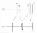
BRIEF DESCRIPTION OF THE DRAWINGSFIG. 1 is a diagram showing lens power arrangement of a zoom lens system according to each Example of the present invention together with movement of each lens group.
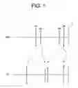
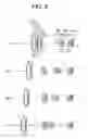
FIG. 2 is diagrams showing the lens arrangement of a zoom lens system according to Example 1 of the present invention in which (W) is a wide-angle end state, (M1) is a first intermediate focal length state, (M2) is a second intermediate focal length state, and (T) is a telephoto end state.
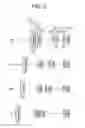
FIGS. 3A and 3B are graphs showing various aberrations of the zoom lens system according to Example 1 of the present invention in which FIG. 3A shows various aberrations in the wide-angle end state W, and FIG. 3B shows those in the first intermediate focal length state M1.
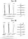
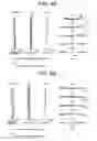
FIGS. 4A and 4B are graphs showing various aberrations of the zoom lens system according to Example 1 of the present invention in which FIG. 4A shows those in the second intermediate focal length state M2, and FIG. 4B shows those in the telephoto end state T.
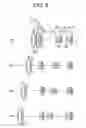
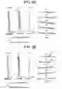
FIG. 5 is diagrams showing the lens arrangement of a zoom lens system according to Example 2 of the present invention in which (W) is a wide-angle end state, (M1) is a first intermediate focal length state, (M2) is a second intermediate focal length state, and (T) is a telephoto end state.
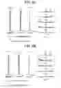
FIGS. 6A and 6B are graphs showing various aberrations of the zoom lens system according to Example 2 of the present invention in which FIG. 6A shows various aberrations in the wide-angle end state W, and FIG. 6B shows those in the first intermediate focal length state M1.
FIGS. 7A and 7B are graphs showing various aberrations of the zoom lens system according to Example 2 of the present invention in which FIG. 7A shows those in the second intermediate focal length state M2, and FIG. 7B shows those in the telephoto end state T.
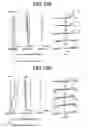
FIG. 8 is diagrams showing the lens arrangement of a zoom lens system according to Example 3 of the present invention in which (W) is a wide-angle end state, (M1) is a first intermediate focal length state, (M2) is a second intermediate focal length state, and (T) is a telephoto end state.
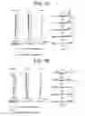
FIGS. 9A and 9B are graphs showing various aberrations of the zoom lens system according to Example 3 of the present invention in which FIG. 9A shows various aberrations in the wide-angle end state W, and FIG. 9B shows those in the first intermediate focal length state M1.
FIGS. 10A and 10B are graphs showing various aberrations of the zoom lens system according to Example 3 of the present invention in which FIG. 10A shows those in the second intermediate focal length state M2, and FIG. 10B shows those in the telephoto end state T.
DESCRIPTION OF THE MOST PREFERRED EMBODIMENTSEmbodiments of the present invention are explained below with reference to accompanying drawings.
A zoom lens system according to the present invention includes, in order from an object, a first lens group having positive refractive power, a second lens group having negative refractive power, a third lens group having positive refractive power, and a fourth lens group having positive refractive power. An aperture stop is disposed to the object side of the third lens group. When a state of lens group positions varies from a wide-angle end state to a telephoto end state, the first, second, third, and fourth lens groups move along the optical axis, and the fourth lens group moves at first to an image side and then to the object side from about an intermediate focal length state forming the zoom trajectory having a convex shape facing to an image.
In a conventional four-lens-group zoom lens system with a fixed fourth lens group, the total lens length increases as increasing the zoom ratio. When applying the restrictions of the lens diameter or the total lens length, optical performance of the zoom lens system has broken down.
On the other hand, in a zoom lens system according to the present invention, when a state of lens group positions varies from the wide-angle end state to the telephoto end state, by moving the fourth lens group in a trajectory having a convex shape facing to the image, the total lens length and the lens diameter of the front lens of the zoom lens system can be drastically decreased, so that the zoom lens system can accomplish both compactness of the lens barrel and a high zoom ratio with securing high optical performance.
In the zoom lens system according to the present invention, the first lens group preferably moves to the object upon zooming from the wide-angle end state to the telephoto end state.
When the zoom ratio becomes high, change in the angle of view from the wide-angle end state to the telephoto end state becomes large, so that when the total lens length is made the same and the first lens group is fixed, the lens diameter of the front lens becomes large upon securing the angle of view in the wide-angle end state. Accordingly, it becomes difficult to make it compact.
On the other hand, in the zoom lens system according to the present invention, by making the first lens group movable and the total lens length variable, the lens barrel of the zoom lens system can be made compact.
In the zoom lens system according to the present invention, the following conditional expression (1) is preferably satisfied:
0.003<(Δ4a+Δ4b)/TLt<0.1 (1)
where Δ4a denotes the absolute value of the moving amount of the fourth lens group along the optical axis from the wide-angle end state to a focal length state where the fourth lens group locates the most image side position upon focusing on infinity, Δ4b denotes the absolute value of the moving amount of the fourth lens group along the optical axis from the focal length state where the fourth lens group locates the most image side position to the telephoto end state upon focusing on infinity, and TLt denotes the total lens length of the zoom lens system in the telephoto end state. By the way, the total lens length means the distance along the optical axis between the most object side of the first lens group to the image plane.
Conditional expression (1) defines an appropriate range of the ratio of the moving amount of the fourth lens group along the optical axis to the total lens length of the zoom lens system in the telephoto end state. When the ratio (Δ4a+Δ4b)/TLt is equal to or falls below the lower limit of conditional expression (1), the total lens length becomes large, so that it becomes impossible to accomplish compactness of the lens barrel. On the other hand, when the ratio (Δ4a+Δ4b)/TLt is equal to or exceeds the upper limit of conditional expression (1), the moving amount of the fourth lens group along the optical axis becomes large and the total lens length cannot be kept compact, so that compactness of the lens barrel cannot be accomplished in addition to affect zooming speed. In order to secure the effect of the present invention, it is preferable to set the lower limit of conditional expression (1) to 0.006 and the upper limit to 0.07.
In the zoom lens system according to the present invention, the following conditional expression (2) is preferably satisfied:
0.003<Δ4a/(fT−fW)<0.1 (2)
where fW denotes the focal length of the zoom lens system in the wide-angle end state, and fT denotes the focal length of the zoom lens system in the telephoto end state.
Conditional expression (2) defines an appropriate range of the moving amount of the fourth lens group along the optical axis from the wide-angle end state to a focal length state where the fourth lens group locates the most image side position upon focusing on infinity. When the ratio Δ4a/(fT−fW) is equal to or falls below the lower limit of conditional expression (2), the optical performance in the intermediate focal length state brakes down. On the other hand, when the ratio Δ4a/(fT−fW) is equal to or exceeds the upper limit of conditional expression (2), the moving amount of the fourth lens group along the optical axis becomes large, so that it is not preferable for constructing the lens barrel. In order to securing the effect of the present invention, it is preferable to set the lower limit of conditional expression (2) to 0.005 and the upper limit to 0.07.
In the zoom lens system according to the present invention, the following conditional expression (3) is preferably satisfied:
0.003<Δ4b/(fT−fW)<0.1 (3).
Conditional expression (3) defines an appropriate range of the moving amount of the fourth lens group along the optical axis from a focal length state where the fourth lens group locates the most image side position to the telephoto end state upon focusing on infinity. When the ratio Δ4b/(fT−fW) is equal to or falls below the lower limit of conditional expression (3), optical performance in the intermediate focal length state and in the telephoto end state brakes down. On the other hand, when the ratio Δ4b/(fT−fW) is equal to or exceeds the upper limit of conditional expression (3), the moving amount of the fourth lens group along the optical axis becomes large, so that it is not preferable for constructing the lens barrel. In order to secure the effect of the present invention, it is preferable to set the lower limit of conditional expression (3) to 0.005 and the upper limit to 0.07.
In the zoom lens system according to the present invention, the following conditional expression (4) is preferably satisfied:
0.005<M·(Δ4a+Δ4b)/f4<2 (4)
where f4 denotes the focal length of the fourth lens group, and M denotes a zoom ratio of the zoom lens system.
Conditional expression (4) defines the moving amount of the fourth lens group along the optical axis by the focal length of the fourth lens group and the zoom ratio. When the ratio M·(Δ4a+Δ4b)/f4 is equal to or falls below the lower limit of conditional expression (4), it becomes difficult to secure optical performance over entire zoom range from the wide-angle end state to the telephoto end state and a high zoom ratio cannot be accomplished. On the other hand, when the ratio M (Δ4a+Δ4b)/f4 is equal to or exceeds the upper limit of conditional expression (4), the moving amount of the fourth lens group along the optical axis becomes large, so that it is not preferable for constructing the lens barrel. In order to secure the effect of the present invention, it is preferable to set the lower limit of conditional expression (4) to 0.1 and the upper limit to 1.4.
In the zoom lens system according to the present invention, the following conditional expression (5) is preferably satisfied:
0.5<fM/(fW·fT)1/2<1.4 (5)
where fM denotes a focal length where the fourth lens group locates the most image side position.
Conditional expression (5) defines an appropriate range of the focal length state where the fourth lens group locates the most image side position. When the ratio fM/(fW−fT)1/2 is equal to or falls below the lower limit of conditional expression (5), spherical aberration and astigmatism come to deteriorate in the intermediate focal length state, so that optical performance cannot be secured over entire zoom range. On the other hand, when the ratio fM/(fW−fT)1/2 is equal to or exceeds the upper limit of conditional expression (5), a high zoom ratio cannot be accomplished. In order to secure the effect of the present invention, it is preferable to set the lower limit of conditional expression (5) to 0.6 and the upper limit to 1.2.
In the zoom lens system according to the present invention, the following conditional expression (6) is preferably satisfied:
0.3<Δ4b/Δ4a<3.0 (6).
Conditional expression (6) defines a ratio of the moving amount of the fourth lens group along the optical axis from the wide-angle end state to a focal length state where the fourth lens group locates to the most image side to that from the focal length state where the fourth lens group locates to the most image side to the telephoto end state upon focusing on infinity. When the ratio Δ4b/Δ4a is equal to or falls below the lower limit of conditional expression (6) or exceeds the upper limit of conditional expression (6), the total lens length becomes large, so that it becomes impossible to accomplish compactness of the lens barrel. In order to secure the effect of the present invention, it is preferable to set the lower limit of conditional expression (6) to 0.6 and the upper limit to 1.5.
In the zoom lens system according to the present invention, focusing from infinity to a close object is carried out by moving the fourth lens group to the object side. By the way, focusing can be carried out by moving the first lens group, the second lens group, or the fourth lens group. Or focusing may be carried out by extending the whole lens system in a body. Alternatively, focusing may be carried out by moving the image plane. In the configuration of the lens barrel, it is more convenient to carry out focusing by moving the fourth lens group.
EmbodimentEach example of a zoom lens system according to the present invention is explained below with reference to accompanying drawings.
FIG. 1 is a diagram showing lens power arrangement of a zoom lens system according to each example of the present invention together with movement of each lens group.
In FIG. 1, a zoom lens system according to each example of the present invention includes, in order from an object, a first lens group G1 having positive refractive power, a second lens group G2 having negative refractive power, a third lens group G3 having positive refractive power, and a fourth lens group G4 having positive refractive power. When a state of lens group positions varies from a wide-angle end state W to a telephoto end state T, a distance between the first lens group G1 and the second lens group G2 increases, a distance between the second lens group G2 and the third lens group G3 decreases, a distance between the third lens group G3 and the fourth lens group G4 varies, and the fourth lens group G4 moves in a trajectory having a convex shape facing to the image plane I.
EXAMPLE 1FIG. 2 is diagrams showing the lens arrangement of a zoom lens system according to Example 1 of the present invention in which (W) is a wide-angle end state, (M1) is a first intermediate focal length state, (M2) is a second intermediate focal length state, and (T) is a telephoto end state. Reference symbols showing each lens element used for explanation below are attached only to the diagram showing the wide-angle end state (W) and duplication is omitted to other diagrams. The same rule is applied to other examples.
A zoom lens system according to Example 1 of the present invention is composed of, in order from the object, a first lens group G1 having positive refractive power, a second lens group G2 having negative refractive power, an aperture stop S, a third lens group G3 having positive refractive power, and a fourth lens group G4 having positive refractive power.
The first lens group G1 having positive refractive power as a whole is composed of, in order from the object, a cemented lens constructed by a negative meniscus lens L11 having a convex surface facing to the object cemented with a double convex positive lens L12, and a positive meniscus lens L13 having a convex surface facing to the object.
The second lens group G2 having negative refractive power as a whole is composed of, in order from the object, a negative meniscus lens L21 having a convex surface facing to the object, a double concave negative lens L22, and a double convex positive lens L23.
The third lens group G3 having positive refractive power as a whole is composed of, in order from the object, a double convex positive lens L31, a cemented lens constructed by a double convex positive lens L32 cemented with a double concave negative lens L33, and a double convex positive lens L34.
The fourth lens group G4 is composed of a double convex positive lens L41.
The aperture stop S is disposed to the object side of the third lens group G3 and moved with the third lens group G3 in a body. In the following Examples including Example 1, a low-pass filter P1 for cutting off the spatial frequency over the resolution limit of a solid-state imaging device D such as a CCD disposed in the image plane I and a cover glass P2 for protecting the solid-state imaging device D are disposed between the fourth lens group G4 and the image plane I.
Various values according to Example 1 are shown in Table 1. In [Specifications], f denotes the focal length, Bf denotes a back focal length, FNO denotes an f-number, and 2ω denotes an angle of view (unit: degrees). In [Lens Data], the first column shows the surface number that is a lens surface counted in order from the object, r denotes the radius of curvature, d denotes a distance between the lens surfaces, v denotes Abbe number at d-line (λ=587.6 nm), and n denote refractive index at d-line (λ=587.56 nm). By the way, r=∞ denotes a plane surface. Refractive index for the air=1.000000 is omitted. In [Aspherical Data], each aspherical coefficient is shown as the aspherical surface is expressed by the following expression:
X(y)=y2/[r·{1+(1−ky2/r2)1/2}]+C4·y4+C6·y6+C8·y8+C10·y10
where y denotes a height from the optical axis, X(y) denotes a distance along the optical axis from tangent plane at the vertex of the aspherical surface to the aspherical surface at the height y, r denotes a reference radius of curvature (paraxial radius of curvature), K denotes a conical coefficient, and Ci denote i-th order aspherical coefficient, respectively. An aspherical surface is denoted by an asterisk (*) attached to the surface number. In [Aspherical Data], “E-n” denotes “10−n”. In [Specifications] and [Variable Distances], focal length f, back focal length Bf, f-number FNO, and angle of view 2ω, or variable distances are shown in the wide-angle end state W, in the first intermediate focal length state M1, in the second intermediate focal length state M2, and in the telephoto end state T. In [Values for Conditional Expressions], values corresponding to respective conditional expressions are shown.
In the tables for various values, “mm” is generally used for the unit of length such as the focal length, the radius of curvature, and the separation between optical surfaces. However, since an optical system proportionally enlarged or reduced its dimension can be obtained similar optical performance, the unit is not necessary to be limited to “mm” and any other suitable unit can be used. The explanation of reference symbols is the same in the other example.
| TABLE 1 |
| [Specifications] |
| W | M1 | M2 | T | ||
| f = | 6.3 | 19 | 30 | 47.9 |
| Bf = | 0.69473 (constant) |
| FNO = | 2.6 | 3.35 | 3.97 | 5.09 | |
| 2ω = | 61.28° | 20.16° | 13.1° | 8.38° | |
| [Lens Data] |
| r | d | ν | n | |
| 1 | 50.7928 | 0.8 | 23.78 | 1.84666 |
| 2 | 29.1817 | 3.2 | 65.47 | 1.603 |
| 3 | −99.7222 | 0.1 | ||
| 4 | 27.5451 | 1.5 | 52.32 | 1.755 |
| 5 | 46.2007 | (d5) | ||
| 6 | 1540.7477 | 0.8 | 54.66 | 1.72916 |
| 7 | 6.173 | 2.5 | ||
| 8 | −13.4291 | 0.8 | 52.32 | 1.755 |
| 9 | 44.8085 | 0.5709 | ||
| 10 | 16.6858 | 1.4 | 23.78 | 1.84666 |
| 11 | −109.8483 | (d11) |
| 12 | ∞ | 0.4 | Aperture Stop S |
| 13* | 10.3942 | 1.6 | 61.3 | 1.58913 |
| 14 | −36.1395 | 0.1 | ||
| 15 | 5.0319 | 2.8 | 81.61 | 1.497 |
| 16 | −14777.27 | 0.8 | 34.96 | 1.801 |
| 17 | 4.3296 | 0.8 | ||
| 18* | 11.9583 | 1.3 | 81.61 | 1.497 |
| 19 | −63.0093 | (d19) | ||
| 20 | 45 | 1.5 | 55.52 | 1.6968 |
| 21 | −23.7314 | (d21) | ||
| 22 | ∞ | 2.62 | 64.14 | 1.51633 |
| 23 | ∞ | 1 | ||
| 24 | ∞ | 0.75 | 64.14 | 1.51633 |
| 25 | ∞ | (Bf) | ||
[Aspherical Data]
| Surface Number 13 | |
| κ = 0.3146 | |
| C4 = 1.00000E−10 | |
| C6 = 2.45500E−07 | |
| C8 = 1.00000E−14 | |
| C10 = 2.80780E−09 | |
| Surface Number 18 | |
| κ = −2.4380 | |
| C4 = −3.28540E−04 | |
| C6 = 1.00000E−12 | |
| C8 = −3.36790E−06 | |
| C10 = 1.00000E−16 | |
[Variable Distances]
| W | M1 | M2 | T | |
| f | 6.3000 | 19.0000 | 30.0000 | 47.9000 | |
| d5 | 1.2792 | 14.1146 | 16.3701 | 17.6261 | |
| d11 | 15.0028 | 7.0057 | 3.4784 | 0.5110 | |
| d19 | 6.0133 | 11.1419 | 15.2478 | 22.7085 | |
| d21 | 0.9257 | 0.6354 | 0.8620 | 0.9257 | |
[Values for Conditional Expressions]
| (1): (Δ4a + Δ4b)/TLt = | 0.009 | |
| (2): Δ4a/(fT − fW) = | 0.007 | |
| (3): Δ4b/(fT − fW) = | 0.007 | |
| (4): M(Δ4a + Δ4b)/f4 = | 0.196 | |
| (5): fM/(fW . fT)1/2 = | 1.094 | |
| (6): Δ4b/Δ4a = | 0.916 | |
FIGS. 3A through 4B are graphs showing various aberrations of the zoom lens system according to Example 1 of the present invention in which FIG. 3A shows various aberrations in the wide-angle end state W, FIG. 3B shows those in the first intermediate focal length state M1, FIG. 4A shows those in the second intermediate focal length state M2, and FIG. 4B shows those in the telephoto end state T.
In respective graphs, FNO denotes an f-number, Y denotes an image height, C denote aberration curve at C-line (λ=656.3 nm), d denotes aberration curve at d-line (587.6 nm), F denotes aberration curve at F-line (λ=486.1 nm), and g denotes aberration curve at g-line (λ=435.8 nm). In graphs showing spherical aberration, f-number shows the value at the maximum aperture and a solid line indicates spherical aberration and a broken line indicates sine condition. In the graphs showing astigmatism and distortion, Y denotes the maximum value of the image height. In the graph showing coma, Y denotes the value of each image height. In the graph showing astigmatism, a solid line indicates a sagittal image plane and a broken line indicates a meridional plane. The above-described explanation regarding various aberration graphs is the same as the other examples.
As is apparent from the respective graphs, the zoom lens system according to Example 1 shows superb optical performance as a result of good corrections to various aberrations in each focal length state from the wide-angle end state to the telephoto end state.
EXAMPLE 2FIG. 5 is diagrams showing the lens arrangement of a zoom lens system according to Example 2 of the present invention in which (W) is a wide-angle end state, (M1) is a first intermediate focal length state, (M2) is a second intermediate focal length state, and (T) is a telephoto end state.
In FIG. 5, the zoom lens system according to Example 2 of the present invention is composed of, in order from an object, a first lens group G1 having positive refractive power, a second lens group G2 having negative refractive power, an aperture stop S, a third lens group G3 having positive refractive power, and a fourth lens group G4 having positive refractive power.
The first lens group G1 having positive refractive power as a whole is composed of, in order from the object, a cemented lens constructed by a negative meniscus lens L11 having a convex surface facing to the object cemented with a double convex positive lens L12, and a positive meniscus lens L13 having a convex surface facing to the object.
The second lens group G2 having negative refractive power as a whole is composed of, in order from the object, a double concave negative lens L21, a double concave negative lens L22, and a double convex positive lens L23.
The third lens group G3 having positive refractive power as a whole is composed of, in order from the object, a double convex positive lens L31, a cemented lens constructed by a double convex positive lens L32 cemented with a double concave negative lens L33, and a double convex positive lens L34.
The fourth lens group G4 is composed of a double convex positive lens L41.
The aperture stop S is disposed to the object side of the third lens group G3 and moved with the third lens group G3 in a body.
Various values according to Example 2 are shown in Table 2.
| TABLE 2 |
| [Specifications] |
| W | M1 | M2 | T | ||
| f = | 6.3 | 11.98 | 26.88 | 48 | |
| Bf = | 0.61 | 0.59 | 0.578 | 0.588 | |
| FNO = | 2.77 | 3.41 | 3.97 | 4.62 | |
| 2ω = | 64.04° | 33.27° | 15.12° | 8.66° | |
| [Lens Data] |
| r | d | ν | n | |
| 1 | 34.1194 | 0.95 | 27.51 | 1.7552 |
| 2 | 21.333 | 4 | 81.61 | 1.497 |
| 3 | −84.5256 | 0.1 | ||
| 4 | 27.3623 | 1.4 | 46.58 | 1.804 |
| 5 | 39.1831 | (d5) | ||
| 6 | −198.4493 | 0.8 | 46.63 | 1.816 |
| 7 | 6.0301 | 2.3 | ||
| 8 | −17.2496 | 0.8 | 54.66 | 1.72916 |
| 9 | 23.9597 | 0.1 | ||
| 10 | 12.3105 | 1.7 | 23.78 | 1.84666 |
| 11 | −133.3487 | (d11) |
| 12 | ∞ | 0.4 | Aperture Stop S |
| 13* | 6.171 | 2.5 | 63.4 | 1.51606 |
| 14* | −17.8808 | 0.1 | ||
| 15 | 6.6043 | 2.4 | 81.61 | 1.497 |
| 16 | −12.2878 | 0.8 | 34.96 | 1.801 |
| 17 | 4.4511 | 0.8 | ||
| 18 | 16.55 | 1.3 | 43.69 | 1.72 |
| 19 | −107.2453 | (d19) | ||
| 20 | 65.8729 | 1.8 | 42.72 | 1.83481 |
| 21 | −33.8068 | (d21) | ||
| 22 | ∞ | 1.65 | 64.14 | 1.51633 |
| 23 | ∞ | 0.4 | ||
| 24 | ∞ | 0.5 | 64.14 | 1.51633 |
| 25 | ∞ | (Bf) | ||
[Aspherical Data]
| Surface Number 13 | |
| κ = 0.3524 | |
| C4 = 1.00000E−10 | |
| C6 = 1.89790E−06 | |
| C8 = −3.88810E−08 | |
| C10 = 1.00000E−16 | |
| Surface Number 14 | |
| κ = −5.3055 | |
| C4 = 1.00000E−10 | |
| C6 = 2.22080E−06 | |
| C8 = −1.37750E−07 | |
| C10 = 1.00000E−16 | |
[Variable Distances]
| W | M1 | M2 | T | |
| f | 6.3018 | 11.9795 | 26.8764 | 48.0147 | |
| d5 | 1.4040 | 8.5770 | 17.0200 | 20.4410 | |
| d11 | 15.3660 | 10.8010 | 5.6710 | 1.5920 | |
| d19 | 4.8830 | 9.5350 | 12.4690 | 15.9910 | |
| d21 | 2.5593 | 1.1192 | 1.6840 | 2.4411 | |
[Values for Conditional Expressions]
| (1): (Δ4a + Δ4b)/TLt = | 0.041 | |
| (2): Δ4a/(fT − fW) = | 0.034 | |
| (3): Δ4b/(fT − fW) = | 0.031 | |
| (4): M(Δ4a + Δ4b)/f4 = | 0.765 | |
| (5): fM/(fW . fT)1/2 = | 0.689 | |
| (6): Δ4b/Δ4a = | 1.000 | |
FIGS. 6A through 7B are graphs showing various aberrations of the zoom lens system according to Example 2 of the present invention in which FIG. 6A shows various aberrations in the wide-angle end state W, FIG. 6B shows those in the first intermediate focal length state M1, FIG. 7A shows those in the second intermediate focal length state M2, and FIG. 7B shows those in the telephoto end state T.
As is apparent from the respective graphs, the zoom lens system according to Example 2 shows superb optical performance as a result of good corrections to various aberrations in each focal length state from the wide-angle end state to the telephoto end state.
EXAMPLE 3FIG. 8 is diagrams showing the lens arrangement of a zoom lens system according to Example 3 of the present invention in which (W) is a wide-angle end state, (M1) is a first intermediate focal length state, (M2) is a second intermediate focal length state, and (T) is a telephoto end state.
In FIG. 8, the zoom lens system according to Example 3 of the present invention is composed of, in order from an object, a first lens group G1 having positive refractive power, a second lens group G2 having negative refractive power, an aperture stop S, a third lens group G3 having positive refractive power, and a fourth lens group G4 having positive refractive power.
The first lens group G1 having positive refractive power as a whole is composed of, in order from the object, a cemented lens constructed by a negative meniscus lens L11 having a convex surface facing to the object cemented with a double convex positive lens L12, and a positive meniscus lens L13 having a convex surface facing to the object.
The second lens group G2 having negative refractive power as a whole is composed of, in order from the object, a double concave negative lens L21, a double concave negative lens L22, and a double convex positive lens L23.
The third lens group G3 having positive refractive power as a whole is composed of, in order from the object, a double convex positive lens L31, a cemented lens constructed by a double convex positive lens L32 cemented with a double concave negative lens L33, and a positive meniscus lens L34 having a convex surface facing to the object.
The fourth lens group G4 is composed of a double convex positive lens L41.
The aperture stop S is disposed to the object side of the third lens group G3 and moved with the third lens group G3 in a body.
Various values according to Example 3 are shown in Table 3.
| TABLE 3 |
| [Specifications] |
| W | M1 | M2 | T | ||
| f = | 7.5 | 22.22 | 37.5 | 66.53 |
| Bf = | 1.63127 (constant) |
| FNO = | 2.61 | 3.54 | 3.81 | 4.84 | |
| 2ω = | 67.83° | 23.14° | 13.84° | 7.95° | |
| [Lens Data] |
| r | d | ν | n | |
| 1 | 45.2848 | 1 | 23.78 | 1.84666 |
| 2 | 31.9444 | 6.3 | 81.61 | 1.497 |
| 3 | −134.5167 | 0.1 | ||
| 4 | 31.8511 | 1.9 | 47.82 | 1.757 |
| 5 | 43.7941 | (d5) | ||
| 6 | −1314.022 | 1 | 46.63 | 1.816 |
| 7 | 8.3694 | 3.19 | ||
| 8 | −20.07 | 1 | 52.32 | 1.755 |
| 9 | 61.8785 | 0.15 | ||
| 10 | 19.536 | 2.2 | 23.78 | 1.84666 |
| 11 | −102.5759 | (d11) |
| 12 | ∞ | 0.5 | Aperture Stop S |
| 13* | 8.3333 | 3.2 | 61.3 | 1.58913 |
| 14* | −32.4601 | 0.1 | ||
| 15 | 14.7517 | 3.5 | 65.47 | 1.603 |
| 16 | −12.7614 | 1.1 | 34.96 | 1.801 |
| 17 | 6.0825 | 1 | ||
| 18 | 13.3827 | 1.8056 | 48.31 | 1.66672 |
| 19 | 104.4609 | (d19) | ||
| 20 | 83.3333 | 2.2222 | 54.66 | 1.72916 |
| 21 | −35.958 | (d21) | ||
| 22 | ∞ | 2 | 64.14 | 1.51633 |
| 23 | ∞ | 0.5 | ||
| 24 | ∞ | 0.5 | 64.14 | 1.51633 |
| 25 | ∞ | (Bf) | ||
[Aspherical Data]
| Surface Number 13 | |
| κ = 0.3036 | |
| C4 = 3.73250E−11 | |
| C6 = 1.15480E−06 | |
| C8 = −4.03990E−09 | |
| C10 = 5.19990E−18 | |
| Surface Number 14 | |
| κ = −10.8985 | |
| C4 = 3.73250E−11 | |
| C6 = 1.42300E−06 | |
| C8 = −2.18410E−08 | |
| C10 = 5.19990E−18 | |
[Variable Distances]
| W | M1 | M2 | T | |
| f | 7.5000 | 22.2222 | 37.5000 | 66.5278 | |
| d5 | 1.7063 | 16.8330 | 23.8501 | 26.6560 | |
| d11 | 26.2279 | 13.0031 | 7.8690 | 1.6326 | |
| d19 | 6.3952 | 14.5234 | 16.1915 | 23.6761 | |
| d21 | 2.0482 | 0.4746 | 1.3436 | 2.1096 | |
[Values for Conditional Expressions]
| (1): (Δ4a + Δ4b)/TLt = | 0.036 | |
| (2): Δ4a/(fT − fW) = | 0.027 | |
| (3): Δ4b/(fT − fW) = | 0.028 | |
| (4): M(Δ4a + Δ4b)/f4 = | 0.820 | |
| (5): fM/(fW · fT)1/2 = | 0.995 | |
| (6): Δ4b/Δ4a = | 1.039 | |
FIGS. 9A through 10B are graphs showing various aberrations of the zoom lens system according to Example 3 of the present invention in which FIG. 9A shows various aberrations in the wide-angle end state W, FIG. 9B shows those in the first intermediate focal length state M1, FIG. 10A shows those in the second intermediate focal length state M2, and FIG. 10B shows those in the telephoto end state T.
As is apparent from the respective graphs, the zoom lens system according to Example 3 shows superb optical performance as a result of good corrections to various aberrations in each focal length state from the wide-angle end state to the telephoto end state.
Incidentally, it is needless to say that although zoom lens systems with a four-lens-group configuration are shown as examples of the present invention, a zoom lens system simply added by a lens group to a four-lens-group configuration is included in the spirit of the present invention. Moreover, in the configuration of each lens group, a lens group simply added by lens elements to the lens group shown in examples is included in the spirit or scope of the present invention.
Additional advantages and modification will readily occur to those skilled in the art. Therefore, the invention in its broader aspects is not limited to the specific details, and representative devices shown and described herein. Accordingly, various modifications may be made without departing from the spirit or scope of the general inventive concept as defined by the appended claims and their equivalents.
Claims
What is claimed is:1. A zoom lens system comprising, in order from an object:
a first lens group having positive refractive power;
a second lens group having negative refractive power;
a third lens group having positive refractive power; and
a fourth lens group having positive refractive power,
wherein when a state of lens group positions varies from a wide-angle end state to a telephoto end state, a distance between the first lens group and the second lens group increases, a distance between the second lens group and the third lens group decreases, and a distance between the third lens group and the fourth lens group varies, and the fourth lens group moves along a zoom trajectory having a convex shape facing to an image.
2. The zoom lens system according to claim 1, wherein when the state of lens group positions varies from the wide-angle end state to the telephoto end state, the first lens group moves to the object.
3. The zoom lens system according to claim 2, wherein the following conditional expression is satisfied:
0.003<(Δ4a+Δ4b)/TLt<0.1
where Δ4a denotes an absolute value of a moving amount of the fourth lens group along the optical axis from the wide-angle end state to a focal length state where the fourth lens group locates the most image side position upon focusing on infinity, Δ4b denotes an absolute value of a moving amount of the fourth lens group along the optical axis from the focal length state where the fourth lens group locates the most image side position to the telephoto end state upon focusing on infinity, and TLt denotes a total lens length of the zoom lens system in the telephoto end state.
4. The zoom lens system according to claim 3, wherein the following conditional expression is satisfied:
0.003<Δ4a/(fT−fW)<0.1
where Δ4a denotes an absolute value of a moving amount of the fourth lens group along the optical axis from the wide-angle end state to a focal length state where the fourth lens group locates the most image side position upon focusing on infinity, fT denote the focal length of the zoom lens system in the telephoto end state, and fW denotes the focal length of the zoom lens system in the wide-angle end state.
5. The zoom lens system according to claim 4, wherein the following conditional expression is satisfied:
0.003<Δ4b/(fT−fW)<0.1
where Δ4b denotes an absolute value of a moving amount of the fourth lens group along the optical axis from the focal length state where the fourth lens group locates the most image side position to the telephoto end state upon focusing on infinity, fT denote the focal length of the zoom lens system in the telephoto end state, and fW denotes the focal length of the zoom lens system in the wide-angle end state.
6. The zoom lens system according to claim 5, wherein the following conditional expression is satisfied:
0.005<M·(Δ4a+Δ4b)/f4<2
where Δ4a denotes an absolute value of a moving amount of the fourth lens group along the optical axis from the wide-angle end state to a focal length state where the fourth lens group locates the most image side position upon focusing on infinity, Δ4b denotes an absolute value of a moving amount of the fourth lens group along the optical axis from the focal length state where the fourth lens group locates the most image side position to the telephoto end state upon focusing on infinity, f4 denotes the focal length of the fourth lens group, M denotes a zoom ratio of the zoom lens system.
7. The zoom lens system according to claim 3, wherein the following conditional expression is satisfied:
0.003<Δ4b/(fT−fW)<0.1
where Δ4b denotes an absolute value of a moving amount of the fourth lens group along the optical axis from the focal length state where the fourth lens group locates the most image side position to the telephoto end state upon focusing on infinity, fT denote the focal length of the zoom lens system in the telephoto end state, and fW denotes the focal length of the zoom lens system in the wide-angle end state.
8. The zoom lens system according to claim 1, wherein the following conditional expression is satisfied:
0.003<(Δ4a+Δ4b)/TLt<0.1
where Δ4a denotes an absolute value of a moving amount of the fourth lens group along the optical axis from the wide-angle end state to a focal length state where the fourth lens group locates the most image side position upon focusing on infinity, Δ4b denotes an absolute value of a moving amount of the fourth lens group along the optical axis from the focal length state where the fourth lens group locates the most image side position to the telephoto end state upon focusing on infinity, and TLt denotes a total lens length of the zoom lens system in the telephoto end state.
9. The zoom lens system according to claim 8, wherein the following conditional expression is satisfied:
0.003<Δ4a/(fT−fW)<0.1
where Δ4a denotes an absolute value of a moving amount of the fourth lens group along the optical axis from the wide-angle end state to a focal length state where the fourth lens group locates the most image side position upon focusing on infinity, fT denote the focal length of the zoom lens system in the telephoto end state, and fW denotes the focal length of the zoom lens system in the wide-angle end state.
10. The zoom lens system according to claim 8, wherein the following conditional expression is satisfied:
0.003<Δ4b/(fT−fW)<0.1
where Δ4b denotes an absolute value of a moving amount of the fourth lens group along the optical axis from the focal length state where the fourth lens group locates the most image side position to the telephoto end state upon focusing on infinity, fT denote the focal length of the zoom lens system in the telephoto end state, and fW denotes the focal length of the zoom lens system in the wide-angle end state.
11. The zoom lens system according to claim 1, wherein the following conditional expression is satisfied:
0.003<Δ4a/(fT−fW)<0.1
where Δ4a denotes an absolute value of a moving amount of the fourth lens group along the optical axis from the wide-angle end state to a focal length state where the fourth lens group locates the most image side position upon focusing on infinity, fT denote the focal length of the zoom lens system in the telephoto end state, and fW denotes the focal length of the zoom lens system in the wide-angle end state.
12. The zoom lens system according to claim 1, wherein the following conditional expression is satisfied:
0.003<Δ4b/(fT−fW)<0.1
where Δ4b denotes an absolute value of a moving amount of the fourth lens group along the optical axis from the focal length state where the fourth lens group locates the most image side position to the telephoto end state upon focusing on infinity, fT denote the focal length of the zoom lens system in the telephoto end state, and fW denotes the focal length of the zoom lens system in the wide-angle end state.
13. The zoom lens system according to claim 1, wherein the following conditional expression is satisfied:
0.005<M·(Δ4a+Δ4b)/f4<2
where Δ4a denotes an absolute value of a moving amount of the fourth lens group along the optical axis from the wide-angle end state to a focal length state where the fourth lens group locates the most image side position upon focusing on infinity, Δ4b denotes an absolute value of a moving amount of the fourth lens group along the optical axis from the focal length state where the fourth lens group locates the most image side position to the telephoto end state upon focusing on infinity, f4 denotes the focal length of the fourth lens group, M denotes a zoom ratio of the zoom lens system.
14. The zoom lens system according to claim 1, wherein the following conditional expression is satisfied:
0.5<fM/(fW·fT)1/2<1.4
where fM denotes the focal length where the fourth lens group locates the most image side position, fW denotes the focal length of the zoom lens system in the wide-angle end state, and fT denotes the focal length of the zoom lens system in the telephoto end state.
15. The zoom lens system according to claim 1, wherein the following conditional expression is satisfied:
0.3<Δ4b/Δ4a<3.0
where Δ4a denotes an absolute value of a moving amount of the fourth lens group along the optical axis from the wide-angle end state to a focal length state where the fourth lens group locates the most image side position upon focusing on infinity, and Δ4b denotes an absolute value of a moving amount of the fourth lens group along the optical axis from the focal length state where the fourth lens group locates the most image side position to the telephoto end state upon focusing on infinity.
16. A zoom lens system comprising, in order from an object:
a first lens group having positive refractive power;
a second lens group having negative refractive power;
a third lens group having positive refractive power; and
a fourth lens group having positive refractive power,
wherein when a state of lens group positions varies from a wide-angle end state to a telephoto end state, a distance between the first lens group and the second lens group varies, a distance between the second lens group and the third lens group varies, and a distance between the third lens group and the fourth lens group varies, and the fourth lens group moves along a zoom trajectory having a convex shape facing to an image.
Images & Drawings included:
Sources:
- United States Patent and Trademark Office - verify current appl. status at the USPTO↗
Similar patent applications:
- » 20170242227
Zoom lens system, interchangeable lens device and camera system with zoom lens system, and imaging apparatus with zoom lens system - » 20090161229
Zoom lens system, optical device with zoom lens system, and method of manufacturing zoom lens system - » 20110096409
Zoom lens system, optical device with zoom lens system, and method of manufacturing zoom lens system - » 20110141575
Zoom lens system, optical apparatus equipped with zoom lens system and method for zooming zoom lens system - » 20090147376
Zoom lens system, optical device with zoom lens system, and method of manufacturing zoom lens system - » 20090244720
Zoom lens system, optical device with the zoom lens system, and method of manufacturing the zoom lens system - » 20130120854
Zoom lens system, optical device with the zoom lens system, and method of manufacturing the zoom lens system - » 20110228406
Zoom lens system, optical device with the zoom lens system, and method of manufacturing the zoom lens system - » 20080198476
Zoom lens system and camera including zoom lens system - » 20180326909
Zoom lens system, imaging device having zoom lens system, and vehicle having imaging device
Recent applications in this class:
- » 20250284104 2025-09-11
ZOOM PROJECTION LENS AND ELECTRONIC DEVICE - » 20250251582 2025-08-07
VARIABLE MAGNIFICATION OPTICAL SYSTEM, OPTICAL DEVICE, AND METHOD FOR PRODUCING VARIABLE MAGNIFICATION OPTICAL SYSTEM - » 20250224600 2025-07-10
STEREOSCOPIC OPTICAL SYSTEM AND IMAGE PICKUP APPARATUS - » 20250164762 2025-05-22
ZOOM OPTICAL SYSTEM, OPTICAL APPARATUS AND METHOD FOR MANUFACTURING THE ZOOM OPTICAL SYSTEM - » 20250076622 2025-03-06
ZOOM OPTICAL SYSTEM, IMAGING DEVICE AND METHOD FOR MANUFACTURING THE ZOOM OPTICAL SYSTEM - » 20240151953 2024-05-09
Zoom optical system, optical apparatus and method for manufacturing the zoom optical system - » 20240151952 2024-05-09
Variable magnification optical system, optical device, and method for producing variable magnification optical system - » 20240142755 2024-05-02
Variable magnification optical system, optical apparatus, and method for producing variable magnification optical system - » 20240053592 2024-02-15
ZOOM LENS AND IMAGE PICKUP APPARATUS - » 20230418035 2023-12-28
ZOOMING OPTICAL SYSTEM, OPTICAL APPARATUS AND METHOD FOR MANUFACTURING ZOOMING OPTICAL SYSTEM
Recent applications for this Assignee:
- » 20250294258 2025-09-18
IMAGE PROCESSING DEVICE AND ELECTRONIC DEVICE - » 20250291167 2025-09-18
QUANTITATIVE PHASE IMAGE GENERATING METHOD, QUANTITATIVE PHASE IMAGE GENERATING DEVICE, AND PROGRAM - » 20250284181 2025-09-11
CAMERA BODY AND INTERCHANGEABLE LENS - » 20250284092 2025-09-11
LENS BARREL AND IMAGING DEVICE - » 20250282628 2025-09-11
POROUS SILICA-CLAY COMPOSITE MATERIAL, WATER PURIFYING AGENT CONTAINING POROUS SILICA-CLAY COMPOSITE MATERIAL, SOIL TREATMENT POWDER CONTAINING POROUS SILICA-CLAY COMPOSITE MATERIAL, AND METHOD OF PRODUCING POROUS SILICA-CLAY COMPOSITE MATERIAL - » 20250279624 2025-09-04
OPTICAL DEVICE, OPTICAL MACHINING DEVICE, MICROSCOPE DEVICE, AND SCANNING METHOD - » 20250279321 2025-09-04
SURFACE POSITION DETECTION DEVICE, EXPOSURE APPARATUS, SUBSTRATE-PROCESSING SYSTEM, AND DEVICE-MANUFACTURING METHOD - » 20250278030 2025-09-04
OBJECT HOLDING DEVICE, EXPOSURE DEVICE, OBJECT MOVING METHOD, AND OBJECT HOLDING SYSTEM - » 20250274562 2025-08-28
ELECTRONIC APPARATUS, REPRODUCTION DEVICE, REPRODUCTION METHOD, RECORDING MEDIUM, AND RECORDING METHOD - » 20250271630 2025-08-28
ACCESSORY