Scaffolding
US20060060422A1
2006-03-23
10/946,814
2004-09-22
Abstract:
Scaffolding comprises a plurality of scaffolding members, each of which comprises an upright and a generally horizontal support member coupled to the upright. A distal end of each support member is configured to rest on a building structure.
Interested in similar patents?
Get notified when new applications in this technology area are published.
Classification:
E04G5/02 » CPC main
Component parts or accessories for scaffolds Scaffold feet, e.g. with arrangements for adjustment
E04G1/14 » CPC further
Scaffolds primarily resting on the ground Comprising essentially pre-assembled two-dimensional frame-like elements, e.g. of rods in L- or H-shape, with or without bracing
E04G1/38 » CPC further
Scaffolds primarily resting on the ground Scaffolds partly supported by the building
E04G5/04 » CPC further
Component parts or accessories for scaffolds Means for fastening, supporting, or bracing scaffolds on or against building constructions
E04G3/00 IPC
Scaffolds essentially supported by building constructions, e.g. adjustable in height
Description
FIELD OF THE INVENTIONThe present invention relates generally to scaffolding.
BACKGROUND OF THE INVENTIONScaffolding to support workers above the ground during construction is well-known in the art and many variations have been considered. One very common type of scaffolding to support workers above the ground during construction of a wall or other structure is shown in FIG. 1 and is generally identified by reference numeral 10. The scaffolding 10 includes a set of four uprights 11, only two of which are shown, bridged by sets of horizontal support members 12. Cross-braces (not shown) extend between pairs of uprights to stabilize the scaffolding. The horizontal support members 12 provide a frame across which a set of planks 13, typically made of wood, are laid to form a platform upon which workers can stand. As progress is made during construction, the horizontal support members 12 are raised and locked in place at new heights, allowing workers standing atop thereof to work on higher sections of the wall being constructed. Additional uprights can be affixed atop the scaffolding, thus allowing higher levels of horizontal support members and platforms to be put in place.
Scaffolding of this nature is generally ground-based i.e. supported either directly or indirectly on the ground surface. When indirectly supported on the ground surface, the uprights are typically placed atop wood blocks 14 that are placed on the ground. The blocks 14 distribute the weight of the scaffolding 10 over a larger area of the ground than provided by the ends of the uprights to inhibit the uprights from sinking into the ground.
Although the above-described scaffolding is common, it is time consuming to erect. Also, during construction of such scaffolding, care must be taken to ensure that the uprights firmly rest on the ground and, thereafter, that each horizontal support member is level. As the scaffolding is generally free-standing, it is also important to ensure that the scaffolding is stable. As will be appreciated, slight shifting in the ground can result in unstable scaffolding or, even worse, its collapse.
It is therefore an object of the present invention to provide novel scaffolding.
SUMMARY OF THE INVENTIONAccordingly, in one aspect of the present invention there is provided scaffolding, comprising a plurality of scaffolding members. Each of the scaffolding members comprises an upright and a generally horizontal support member coupled to the upright. A distal end of the support member is configured to rest on a building structure.
In one embodiment, the support member includes a wall bracket at the distal end of the support member. The wall bracket includes a generally horizontal tongue extending from the support member. The tongue is vertically spaced from the support member and has a thickness substantially equal to the thickness of a layer of cement placed between layers of bricks forming a wall. Opposite sides of the tongue are inwardly tapered in a direction towards the distal end. The wall bracket also includes a web oriented generally at a right angle to the support member that bridges the support member and the tongue. The web extends upwardly from the support member to position the tongue above the support member.
According to another aspect of the present invention there is provided a scaffolding member comprising an upright and a horizontal support member coupled to the upright at one end. The support member has a bracket at an opposite end thereof. The bracket is configured to rest on a building structure.
The present scaffolding takes advantage of a previously-built structure, such as for example a foundation wall, to provide support. By resting the scaffolding on the foundation wall, the scaffolding is no longer a free-standing structure. A portion of the load on the scaffolding is distributed downwardly to the foundation wall. As fewer uprights rest on the ground, which is generally less stable than the foundation wall, undesired shifting of the scaffolding is avoided. Further, as fewer cross-braces are required, the scaffolding can be erected quickly, efficiently and safely.
BRIEF DESCRIPTION OF THE DRAWINGSAn embodiment will now be described, by way of example only, with reference to the accompanying drawings in which:
FIG. 1 is a side schematic view of prior art scaffolding;
FIG. 2 is an isometric view of scaffolding adjacent a building foundation wall in accordance with the present invention;
FIG. 3 is a side schematic view of a scaffolding member forming part of the scaffolding of FIG. 2; and
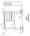
FIG. 4 is a side schematic view of the scaffolding of FIG. 2, supporting a level of conventional scaffolding.
DETAILED DESCRIPTION OF THE INVENTIONFIG. 2 shows the present scaffolding 20 that takes advantage of a previously built structure such as for example, a completed building foundation wall 24 on which framing 26 is constructed, to provide support for the scaffolding. As a result, the scaffolding 20 is more stable than prior art scaffolding since the scaffolding 20 distributes weight on the foundation wall 24.
Scaffolding 20 includes a pair of scaffolding members 32 spaced approximately eighty-four inches apart and coupled together by cross-braces 34 to stabilize the scaffolding 20 and inhibit lateral movement of the scaffolding members 32. As the scaffolding members 32 are identified only one will be described.
As can be seen in FIGS. 2 and 3, the scaffolding member 32 comprises an upright 36 coupled to a horizontal support member 56. The upright 36 is constructed from a four-foot length of two-inch by two-inch steel tubing. A threaded bolt 40 extends from the bottom of the upright 36. As the inner dimensions of the upright 36 are sized to just accommodate the threaded bolt 40, the threaded bolt 40 slides into the interior of the upright 36 with some resistance to inhibit the threaded bolt 40 from simply sliding out of the bottom end of the upright 36 when the upright 36 is not in use. A foot 44 is secured to the bottom end of the threaded bolt 40. The foot 44 in this embodiment is a plate of metal that is wider than the upright 36. The foot 44 distributes the weight borne by the upright 36, and reduces lateral slippage. A wingnut 48 is threaded onto the threaded bolt 40 between the upright 36 and the foot 44.
The upright 36 has a plurality of through-holes 52 provided therein. The through-holes 52 are generally evenly spaced substantially along the length of the upright 36. The through-holes 52 are one half-inch in diameter and are spaced about six inches apart.
The horizontal support member 56 is constructed from two-inch by three-inch steel tubing and is approximately 88 inches in length. As the horizontal support member 56 must bear significant weight, it is oriented such that its depth (vertical height when in position) is greater than its width (lateral width across) to provide additional resistance to the vertical force of gravity. The horizontal support member 56 has a sleeve 60 welded to one end that is complementary in shape to the upright 36. In this embodiment, the sleeve 60 is constructed from a four-inch length of two-and-one-half inch by two-and-one-half inch generally rectangular steel tubing. The sleeve 60 has a lengthwise passage that is dimensioned to slidably receive the upright 36. Aligned holes 64 are centrally disposed in two opposite lateral sides of the sleeve 60. The dimensions of the holes 64 are similar to through-holes 52. An L-shaped adjusting pin 68 is connected to the sleeve 60 via a cable 70. The adjusting pin 68 in this embodiment is a one half-inch diameter bent metal bolt. The adjusting pin 68 is sized to pass through the sleeve 60 and upright 36 when the holes 64 in the sleeve 60 are brought into alignment with one of the through-holes 52 in the upright 36.
A pair of upstanding bracing pins 72a, 72b is provided on the surface of the horizontal support member 56 for receiving the cross-braces 34. The bracing pins 72a, 72b are one-inch long, half-inch diameter steel rods that are welded to the upper surface of the horizontal support member 56. Bracing pin 72a is located six inches from the sleeve 60, and bracing pin 72b is located forty-two inches from bracing pin 72a. A pair of upstanding scaffold pins 76a and 76b for receiving scaffolding uprights is provided on the upper surface of the horizontal support member 56. Scaffolding pin 76a is located three inches from the sleeve 60, and scaffolding pin 76b is located forty-eight inches from the scaffolding pin 76a. The scaffolding pins 76a, 76b in this embodiment are two-and-one-half inches long, one-inch diameter steel rods that are welded to the horizontal support member 56.
The horizontal support member 56 has a wall bracket 80 at its other end opposite the sleeve 60. The wall bracket 80 is constructed of a half-inch thick steel plate that is bent to form an angle defining a generally planar horizontal tongue 84 and a generally vertical joining web 86. The tongue 84 is four inches long, four inches wide, has tapered sides, and a thickness of about one-half inch and is angled slightly downwards. The joining web 86 is oriented generally to form a right angle with the horizontal support member 56 and is welded thereto.
Turning now to FIGS. 2 to 4, deployment of the scaffolding 20 during construction of a wall will be described. Initially, the ground where feet 44 will rest is prepared by packing it down to reduce the chance of the ground shifting at a later time. With the wingnuts 48 rotated until they are adjacent the feet 44, the feet 44 are placed either directly on the ground or atop wooden blocks 86, as shown in FIGS. 3 and 4. Where wooden blocks 86 are employed, the wooden blocks 86 are typically selected to have a larger surface area than the feet 44 to further distribute the weight borne by the scaffolding 20 and to reduce lateral slippage.
The scaffolding members 32 are then assembled by sliding the sleeves 60 of the horizontal support members 56 onto the uprights 36 and placing the tongues 84 of the wall brackets 80 onto the upper outer corner of the foundation wall 24 where work is to be performed.
For each scaffolding member 32, with its foot 44 either resting on the ground or on the wooden block 86, the sleeve 60 is adjusted until the horizontal support member 56 is level. If the holes 64 in the sleeve 60 are aligned with a through-hole 52 in the upright 36 at this point, the adjusting pin 68 is placed through both the sleeve holes 64 and the through-hole 52 in the upright 36, and the height adjustment of the horizontal support member 56 is complete.
If the holes 64 in the sleeve 60 are not aligned with a through-hole 52 in the upright 36 when the horizontal support member 56 is level, the sleeve 60 is slid downwards along the upright 36 until the holes 64 in the sleeve 60 are aligned with the most proximal through-hole 52 in the upright 36. At this point, the adjusting pin 68 is inserted through the holes 64 in the sleeve and the through-hole 52 in the upright 36. The wingnut 48 is then turned counter-clockwise to raise it from the foot 44. As the wingnut 48 is raised, the upright 36 is raised with it as the bottom end of the upright 36 rests on the wingnut 48. The wingnut 48 is turned in this fashion until the horizontal support member 56 is raised to a level disposition.
FIG. 3 better illustrates one of the scaffolding members 32 after deployment. As can be seen, the foot 44 of the upright 36 rests on the wooden block 86. The tongue 84 rests atop the foundation wall 24. The sleeve 60 and wingnut 48 are positioned such that horizontal support member 56 is level.
Once both of the scaffolding members 32 are deployed and are oriented as shown in FIG. 3, the cross-braces 34 are attached to the horizontal support members 56 via the bracing pins 72a, 72b. Once the cross-braces 34 are installed on the bracing pins 72a, 72b, locking pins 92 are placed through small through-holes in the bracing pins 72a, 72b to retain the cross-braces 34.
With the scaffolding 20 erected in the above manner, construction of the wall atop the foundation wall 24 can be commenced. During construction of a wall on the foundation 24, a layer of cement 96 is laid upon the exposed upper surface of the foundation wall 24. The thickness of each tongue 84 is generally to be the same as that of the layer of cement laid on the foundation wall 24. The cement 96 generally is applied to the areas around, but not touching, the tongues 84. A layer of bricks 98 is then laid atop of the layer of cement 96 and the tongues 84. Subsequent layers of cement 96 and bricks 98 are then laid.
FIG. 4 illustrates the scaffolding 20 of FIG. 3, showing the tongue 84 of one of the scaffolding members 32 wedged under a number of layers of bricks 98. The bracket 80 is designed such that the load on the scaffolding 20 is principally redirected downward on the top of the foundation wall 24. A small component of the force is however directed towards the foundation wall 24.
In FIG. 4, the scaffolding 20 is also shown supporting an additional level of scaffolding 99. Scaffolding 99 includes uprights 100 placed atop the horizontal support members 56, over the scaffolding pins 76a, 76b. The pins 76a and 76b are roughly the same size as the internal diameter of the additional scaffolding uprights 100 and thus provide a secure fit. The scaffolding pins 76a, 76b are also sufficiently long to inhibit the scaffolding from being removed from the scaffolding 20 vertically. Crossbeams 104 extend between adjacent pairs of the scaffolding uprights 100 to provide stability to the scaffolding 99 and to serve as supports for platforms. Additional cross-braces (not shown) are affixed to the scaffolding uprights 100 and the crossbeams 104 to further stabilize the scaffolding 99.
Planks 108 are deployed across the crossbeams 104 to form platforms on which workers can stand allowing workers to work on higher portions of the wall. Planks 108 can also be deployed across the horizontal support members 56 adjacent the wall brackets 80 to form an additional work platform. As will be appreciated additional scaffolding 99 and platforms can be added on as required to accommodate the needs of the building project.
Upon completion of the wall, when the scaffolding 20 is no longer required, the additional scaffolding 99 built atop the scaffolding 20, if it exists, is disassembled as scaffolding typically is. Next, the cross-braces 34 are removed from the horizontal support members 56. Once the cross-braces 34 have been removed, the tongues 84 are removed from the wall. This is typically achieved by applying force on the uprights 36 in a direction away from the wall. As the tongues 84 are tapered in width, and no or little contact is made between the tongues 84 and the cement 96 to bind the tongues 84 in place, they are generally readily removed from between the bricks 98 and the foundation wall 24. It will be appreciated, however, that some contact between the cement placed on the foundation and the tongues may occur without restricting removal of the tongues from the constructed wall. The voids in the wall left once the tongues 84 of the scaffolding 20 are then filled with cement.
While the bracket 80 has been illustrated as being generally L-shaped, other variations will occur to those skilled in the art. Additionally, where the exterior of the wall being constructed is not perpendicular to a level plane, the angle of the wall bracket can be altered correspondingly.
The scaffolding members are described as including sleeves slidable along uprights and lockable along the uprights using pins. Those of skill in the art will appreciate that any suitable adjusting mechanism can be employed to lock the horizontal support members at set heights along the uprights.
While the described embodiment makes use of pins along the upper surface of the horizontal support members to retain the uprights of additional scaffolding, other means for securing additional scaffolding uprights atop the scaffolding members will occur to those of skill in the art. For example, brackets can be welded onto the top surface of the horizontal support members to securely restrict lateral movement of additional scaffolding uprights placed on the scaffolding members. In this case, the brackets are dimensioned to restrict accidental slippage of the additional scaffolding uprights.
Gussets can be employed between the horizontal support members and the brackets to strengthen the joint therebetween and to reduce bending of the tongues.
Although a preferred embodiment has been described, those of skill in the art will appreciate that variations and modifications may be made without departing from the spirit and scope thereof as defined by the appended claims.
Claims
What is claimed is:1. Scaffolding, comprising:
a plurality of scaffolding members, each of said scaffolding members comprising an upright and a generally horizontal support member coupled to said upright, a distal end of said support member being configured to rest on a building structure
2. Scaffolding according to claim 1, wherein said support member includes a wall bracket at said distal end.
3. Scaffolding according to claim 2, wherein said wall bracket includes a generally horizontal tongue extending from said support member.
4. Scaffolding according to claim 3, wherein said tongue is vertically spaced from said support member.
5. Scaffolding according to claim 4, wherein said tongue has a thickness substantially equal to the thickness of a layer of cement placed between layers of bricks forming a wall.
6. Scaffolding according to claim 5, wherein opposite sides said tongue are inwardly tapered in a direction towards said distal end.
7. Scaffolding according to claim 5, wherein said wall bracket includes a web oriented generally at a right angle to said support member and bridging said support member and tongue, said web extending upwardly from said support member to position said tongue above said support member.
8. Scaffolding according to claim 7, wherein said web and tongue form an angle equal to about 90 degrees.
9. Scaffolding according to claim 4, wherein said building structure is a foundation wall.
10. Scaffolding according to claim 3, where said support members are moveable along and lockable to said uprights at selected positions.
11. Scaffolding according to claim 10, further comprising:
cross bracing extending between said scaffolding members to inhibit lateral movement therebetween.
12. Scaffolding according to claim 11 wherein said cross bracing engages pins on said support members.
13. Scaffolding according to claim 12, wherein opposite sides said tongue are inwardly tapered in a direction towards said distal end.
14. Scaffolding according to claim 11 further comprising scaffolding retaining pins on said support memebers.
15. A scaffodling member, comprising:
an upright; and
a horizontal support member coupled to said upright at one end and having a bracket at an opposite end, said bracket being configured to rest on a building structure.
16. A scaffolding member according to claim 15, wherein said bracket includes a generally horizontal tongue extending from said support member.
17. A scaffolding member according to claim 16, wherein said tongue is vertically spaced from said support member.
18. A scaffolding member according to claim 17, wherein said tongue has a thickness substantially equal to the thickness of a layer of cement placed between layers of bricks forming a wall.
19. A scaffolding member according to claim 18, wherein opposite sides said tongue are inwardly tapered in a direction towards said distal end.
20. A scaffolding member according to claim 19, wherein said web and tongue form an angle equal to about 90 degrees.
Images & Drawings included:


Sources:
- United States Patent and Trademark Office - verify current appl. status at the USPTO↗
Similar patent applications:
- » 20180119434
SCAFFOLD PART AND SCAFFOLD HAVING SUCH A SCAFFOLD PART - » 20200217090
SCAFFOLDING CROSSBAR, SCAFFOLDING AND METHOD FOR CONSTRUCTING SCAFFOLDING - » 20150068841
Vertical support member for a suspended scaffold assembly, kit for mounting a suspended scaffold assembly, suspended scaffold assembly and method for mounting the same - » 20180073258
Scaffold with scaffold holder receptable and use of an aperture in a scaffold pole - » 20190309532
SUPPLY SCAFFOLD FOR ARRANGING IN THE INTERIOR OF A TOWER, SCAFFOLD MODULE, TOWER, WIND TURBINE AND METHOD FOR ERECTING AND/OR OPERATING A SUPPLY SCAFFOLD AND FOR ERECTING A TOWER - » 20200095784
Scaffold transport system, method for controlling a scaffold transport system and use of a scaffold transport system - » 20060157302
Scaffold, and girder intended for such a scaffold, and method for building a scaffold - » 20130330117
Scaffolding component with at least one connection head and method for fastening a scaffolding component having at least one connection head to a vertical scaffolding element - » 20160153205
Scaffolding pipe of a structural scaffolding system and scaffolding element - » 20230003037
HANDRAIL, SCAFFOLD, METHOD OF ERECTING A SCAFFOLD AND USE OF A HANDRAIL IN A SCAFFOLD
Recent applications in this class:
- » 20150075911 2015-03-19
Supporting element for scaffolds - » 20110085884 2011-04-14
Multi-directional transport device for scaffolding - » 20100025155 2010-02-04
Reusable Mud-Sill - » 20090026013 2009-01-29
Adjustable and transportable scaffolding - » 20080168740 2008-07-17
Mud sill - » 20050126856 2005-06-16
Screw jack socket