System for evaluating luminance and movement within an observation space, and method for controlling light sources within the observation space
US20060071153A1
2006-04-06
11/226,376
2005-09-15
✅ Patent granted
US 7,459,661 B2
2008-12-02
-
-
Georgia Y Epps | Pascal M Bui-Pho
2025-09-15
Abstract:
A sensor system has a video camera and an evaluation unit, the evaluation unit receiving a video signal from the video camera and providing output information relating to luminance and movement of an observation space. The evaluation unit can include a microcontroller that undertakes calculations in order to provide the output information. However, the sensor system can be included in a light control system. A method for controlling an artificial light component of controllable light sources via a light control system includes: picking up a video signal, relaying the video signal to the input of the evaluation unit, evaluating the video signal with reference to luminance and movement in the evaluation unit, outputting the information relating to luminance and movement at the output of the evaluation unit to a control unit and setting a desired brightness of the controllable light sources via the control unit.
Assignee:
- PATENT-TREUHAND-GESELLSCHAFT FUR ELEKTRISCHE GLUHLAMPEN MBH 165 🇩🇪 MUNCHEN, Germany
- Patent-Treuhand-Gesellschaft Fur Elektrisch Gluhlampen MBH 49 🇩🇪 Munchen, Germany
Interested in similar patents?
Get notified when new applications in this technology area are published.
Classification:
H05B47/11 » CPC main
Circuit arrangements for operating light sources in general, i.e. where the type of light source is not relevant; Controlling the light source in response to determined parameters by determining the brightness or colour temperature of ambient light
G08B5/36 » CPC further
Visible signalling systems, e.g. personal calling systems, remote indication of seats occupied using electric transmission; using electromagnetic transmission using visible light sources
G08B13/196 » CPC further
Burglar, theft or intruder alarms; Actuation by interference with heat, light, or radiation of shorter wavelength; Actuation by intruding sources of heat, light, or radiation of shorter wavelength using passive radiation detection systems using image scanning and comparing systems using television cameras
Y02B20/40 » CPC further
Energy efficient lighting technologies, e.g. halogen lamps or gas discharge lamps Control techniques providing energy savings, e.g. smart controller or presence detection
Y02B20/40 » CPC further
Energy efficient lighting technologies, e.g. halogen lamps or gas discharge lamps Control techniques providing energy savings, e.g. smart controller or presence detection
G06M7/00 IPC
Counting of objects carried by a conveyor
G06M7/00 IPC
Counting of objects
G01J1/32 IPC
Photometry, e.g. photographic exposure meter by comparison with reference light or electric value provisionally void intensity of the measured or reference value being varied to equalise their effects at the detectors, e.g. by varying incidence angle using variation of intensity or distance of source using electric radiation detectors adapted for automatic variation of the measured or reference value
H01J40/14 IPC
Photoelectric discharge tubes not involving the ionisation of a gas; Details Circuit arrangements not adapted to a particular application of the tube and not otherwise provided for
Description
FIELD OF THE INVENTIONThe present invention relates to a sensor system having a video camera and an evaluation unit. The evaluation unit has an input and an output, the input receiving a video signal from the video camera, and the output providing output information relating to luminance and movement of an observation space. It also relates to a method for controlling an artificial light component of controllable light sources by means of a light control system. In this case, a video signal is picked up by a video camera, relayed to the input of the evaluation unit and evaluated in the evaluation unit with reference to luminance and movement. At the output of the evaluation unit, the information relating to luminance and movement is output to a control unit that sets a desired brightness of the controllable light sources.
BACKGROUND OF THE INVENTIONLight control systems are known that control or regulate artificial light as a function of movement and luminance with the aid of motion detectors (as a rule, PIR sensors) and light sensors (photoresistors or phototransistors or photodiodes). The measurement signals are fed to a controller that controls the artificial light sources. Light control systems for a number of light sources or large observation spaces require a number of motion detectors in order to cover the entire space, as well as a number of light sensors. This results overall in a large number of various sensors that must be set separately to the desired area of coverage and cause a high outlay on installation. Moreover, overlaps in the areas of coverage are often unavoidable, chiefly in the case of the light sensors, and interfere with the function. Specific areas in the field of coverage of a sensor cannot be masked out in order, for example, to exclude the interpretation of a fan as movement.
SUMMARY OF THE INVENTIONIt is an object of the present invention to provide a sensor system in order to control an artificial light component.
According to the invention, a sensor system having a video camera and an evaluation unit is provided, the input of the evaluation unit receiving a video signal from the video camera, and the output of the evaluation unit providing output information relating to luminance and movement of an observation space.
The video camera of the sensor system preferably includes a CCD, MOS chip or other chip technologies in order to take up image information.
In a preferred design of the sensor system, the evaluation unit includes a microcontroller or a digital signal processor (DSP) that undertakes calculations in order to provide the output information. In the case of relatively large light systems, these calculations can also be executed by a computer system having equipment for processing video signals.
A particularly preferred embodiment of the sensor system provides dividing the observation space into various zones and weighting the latter differently during an evaluation. For example, it is also possible to provide a large observation space for the coverage of movement, and to perform the coverage of the luminance only in a section of the large observation space.
Further preferred embodiments follow from the subclaims.
BRIEF DESCRIPTION OF THE DRAWINGSThe invention is to be explained in more detail below with the aid of exemplary embodiments and with reference to drawings, in which:
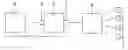
FIG. 1 shows a schematic of the design of a system for controlling an artificial light component, and
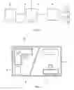
FIG. 2 shows a schematic of a video image having various zones that can be differently weighted during evaluation.
DETAILED DESCRIPTION OF THE INVENTIONFIG. 1 shows the design of a system for controlling an artificial light component. The light control system includes the sensor system 1 and the control unit 6. A video camera 2 picks up a video image of an observation space. The video camera 2 is connected to an evaluation unit 3 and relays the video signal to the input 4 of the evaluation unit 3. The video camera 2 and the evaluation unit 3 form the sensor system 1. The video signal is evaluated in the evaluation unit 3 with reference to luminance and movement in the observation space. The evaluation unit 3 is connected to the control unit 6. The control unit 6 obtains the information relating to luminance and movement from the output 5 of the evaluation unit 3. The control unit 6 sets the desired brightness of the controllable light sources 7.
FIG. 2 shows a video image of an observation space 8 that relates to an office situation. Depicted on the video image are various zones 9-12 that are to be differently weighted in the exemplary embodiment during evaluation with reference to movement and luminance. The video image can, for example, be divided into a zone 9 for information relating to movement over workplace 1, a zone 10 (desk) for information relating to luminance over workplace 1, a zone 11 for information relating to movement over workplace 2, and a zone 12 for information relating to luminance over workplace 2.
Claims
1. A sensor system having a video camera and an evaluation unit, characterized in that the evaluation unit has an input and an output, the input receiving a video signal from the video camera, and the output providing output information relating to luminance and movement of an observation space.
2. The sensor system as claimed in claim 1, characterized in that the video camera includes a CCD or MOS chip.
3. The sensor system as claimed in claim 1, characterized in that the evaluation unit includes a microcontroller or DSP that undertakes calculations in order to provide the output information.
4. The sensor system as claimed in claim 1, characterized in that the evaluation unit includes a computer system with equipment for processing video signals that undertakes calculations in order to provide the output information.
5. The sensor system as claimed in claim 1, characterized in that the observation space can be divided into various zones, and the latter can be weighted differently during an evaluation.
6. The sensor system as claimed in claim 1, characterized in that the video camera can be used for monitoring purposes.
7. A light control system characterized in that it comprises a sensor system as claimed in claim 1.
8. A method for controlling an artificial light component of controllable light sources by means of a light control system, characterized by the following steps:
picking up a video signal by a video camera
relaying the video signal to the input of the evaluation unit
evaluating the video signal with reference to luminance and movement in the evaluation unit
outputting the information relating to luminance and movement at the output of the evaluation unit to a control unit
setting a desired brightness of the controllable light sources by means of the control unit in accordance with prescribed setpoints.
9. The sensor system as claimed in claim 2, characterized in that the evaluation unit includes a microcontroller or DSP that undertakes calculations in order to provide the output information.
10. The sensor system as claimed in claim 2, characterized in that the evaluation unit includes a computer system with equipment for processing video signals that undertakes calculations in order to provide the output information.
Images & Drawings included:
Sources:
- United States Patent and Trademark Office - verify current appl. status at the USPTO↗
Recent applications in this class:
- » 20250294658 2025-09-18
Wearable light emitting device having a controllable light output in different angular bins - » 20250275039 2025-08-28
Light emitting system selectively increasing light toward an individual - » 20250275038 2025-08-28
Angularly varying light emitting device increasing contrast - » 20250275037 2025-08-28
Angularly varying light emitting device emitting light with wavelengths greater than 700 nanometers - » 20250275036 2025-08-28
Angularly varying light emitting device excluding television illumination - » 20250275035 2025-08-28
Light emitting device prioritizing illumination or irradiation modes - » 20250275034 2025-08-28
Method for controlling light sources of a lighting system - » 20250275033 2025-08-28
Angularly varying light emitting device with individually addressable light sources and an optical element - » 20250275032 2025-08-28
Light emitting device with an array of individually addressable visible light sources, ultraviolet light sources, and an imager - » 20250275031 2025-08-28
Light emitting device emitting light into different angular bins and illuminating a pathway and a form of an image, video, indicia, or graphic
Recent applications for this Assignee:
- » 20110062851 2011-03-17
Holding Rod - » 20100134037 2010-06-03
Light source emitting mixed-colored light and method for controlling the color locus of such a light source - » 20090316418 2009-12-24
Component With a Weld Projection Having a Projection and Lamp Housing Part Comprising a Component with a Weld Projection - » 20090295308 2009-12-03
Method for operating high-pressure lamps without hotstarting and luminaire having two high-pressure discharge lamps - » 20090295301 2009-12-03
Self-exciting step-up converter - » 20090289563 2009-11-26
Circuit Arrangement and Method for Operating At Least One Dielectric Barrier Discharge Lamp - » 20090284154 2009-11-19
Low-pressure gas discharge lamp with a reduced argon proportion in the gas filling - » 20090278441 2009-11-12
Luminescence conversion of LED including two phosphors - » 20090251895 2009-10-08
Lighting system - » 20090243486 2009-10-01
Discharge Lamp