Porous Ceramic Carrier
US20060078710A1
2006-04-13
10/963,454
2004-10-13
Abstract:
A porous ceramic carrier includes a main body having an inside provided with a plurality of intersecting separation walls formed with a plurality of through holes, wherein the separation walls have connections each formed with a cylindrical portion. Thus, each of the through holes of the separation walls has smooth corners instead of sharp corners so as to reduce the stress applied on the surface of each of the through holes, thereby preventing the connections of the separation walls from being worn or broken due to a stress concentration.
Interested in similar patents?
Get notified when new applications in this technology area are published.
Classification:
B01J35/04 » CPC main
Catalysts, in general, characterised by their form or physical properties; Solids Foraminous structures, sieves, grids, honeycombs
C04B2111/0081 » CPC further
Mortars, concrete or artificial stone or mixtures to prepare them, characterised by specific function, property or use; Uses not provided for elsewhere in as catalysts or catalyst carriers
C04B2111/343 » CPC further
Mortars, concrete or artificial stone or mixtures to prepare them, characterised by specific function, property or use; Non-shrinking or non-cracking materials Crack resistant materials
Y10T428/218 » CPC further
Stock material or miscellaneous articles; Circular sheet or circular blank Aperture containing
Y10T428/24273 » CPC further
Stock material or miscellaneous articles; Structurally defined web or sheet [e.g., overall dimension, etc.] including aperture
C04B38/0009 » CPC further
Porous mortars, concrete, artificial stone or ceramic ware; Preparation thereof; Honeycomb structures characterised by features relating to the cell walls, e.g. wall thickness or distribution of pores in the walls
C04B35/00 » CPC further
Shaped ceramic products characterised by their composition ; Ceramics compositions ; Processing powders of inorganic compounds preparatory to the manufacturing of ceramic products
B32B3/10 IPC
Layered products comprising a layer with external or internal discontinuities or unevennesses, or a layer of non-planar form ; Layered products having particular features of form characterised by a discontinuous layer, i.e. formed of separate pieces of material
Description
BACKGROUND OF THE INVENTION1. Field of the Invention
The present invention relates to a porous ceramic carrier, and more particularly to a having an enhanced strength.
2. Description of the Related Art
A porous ceramic carrier is used in a catalyst such as a far infrared catalyst, a heating element or an electrically conduction element. The porous ceramic carrier does not need secondary heat transfer when in use, so that the porous ceramic carrier is heated rapidly, evenly and safely with a higher thermal efficiency.
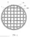
A conventional porous ceramic carrier in accordance with the prior art shown in FIG. 2 comprises a main body 1 having an inside provided with a plurality of intersecting separation walls 11 formed with a plurality of through holes 10. Each of the through holes 10 has four sharp corners 12. However, when fluid passes through the through holes 10, the sharp corners 12 of each of the through holes 10 easily cause a stress concentration, so that the sharp corners 12 are easily worn or broken due to the stress concentration, thereby wearing or breaking the connections of the separation walls 11.
SUMMARY OF THE INVENTIONIn accordance with the present invention, there is provided a porous ceramic carrier, comprising a main body having an inside provided with a plurality of intersecting separation walls formed with a plurality of through holes, wherein the separation walls have intersecting connections each formed with a cylindrical portion.
The primary objective of the present invention is to provide a porous ceramic carrier having an enhanced strength.
Another objective of the present invention is to provide a porous ceramic carrier, wherein each of the through holes of the separation walls has smooth corners instead of sharp corners so as to reduce the stress applied on the surface of each of the through holes, thereby preventing the connections of the separation walls from being worn or broken due to a stress concentration.
Further benefits and advantages of the present invention will become apparent after a careful reading of the detailed description with appropriate reference to the accompanying drawings.
BRIEF DESCRIPTION OF THE DRAWINGSFIG. 1 is a plan cross-sectional view of a porous ceramic carrier in accordance with the preferred embodiment of the present invention; and
FIG. 2 is a plan cross-sectional view of a conventional porous ceramic carrier in accordance with the prior art.
DETAILED DESCRIPTION OF THE INVENTIONReferring FIG. 1, a porous ceramic carrier in accordance with the preferred embodiment of the present invention comprises a main body 2 having an inside provided with a plurality of intersecting separation walls 21 formed with a plurality of through holes 20. Preferably, the main body 2 is formed integrally by an extruding process and has a proper shape, such as circular or square. The surface of each of the through holes 20 is used to function as a bed for attaching a functional material.
In addition, the separation walls 21 have intersecting connections each formed with a cylindrical portion 22. The cylindrical portion 22 of each of the connections of the separation walls 21 has a portion extended into the through holes 20 and located at a corner of each of the through holes 20, so that each of the through holes 20 has arc-shaped corners 202. Thus, each of the through holes 20 has arc-shaped corners 202 instead of sharp corners so as to reduce the stress applied on the surface of each of the through holes 20, thereby preventing the connections of the separation walls 21 from being worn or broken due to a stress concentration.
Accordingly, each of the through holes 20 of the separation walls 21 has smooth corners 202 instead of sharp corners so as to reduce the stress applied on the surface of each of the through holes 20, thereby preventing the connections of the separation walls 21 from being worn or broken due to a stress concentration.
Although the invention has been explained in relation to its preferred embodiment(s) as mentioned above, it is to be understood that many other possible modifications and variations can be made without departing from the scope of the present invention. It is, therefore, contemplated that the appended claim or claims will cover such modifications and variations that fall within the true scope of the invention.
Claims
What is claimed is:1. A porous ceramic carrier, comprising a main body having an inside provided with a plurality of intersecting separation walls formed with a plurality of through holes, wherein the separation walls have intersecting connections each formed with a cylindrical portion.
2. The porous ceramic carrier in accordance with claim 1, wherein the cylindrical portion of each of the connections of the separation walls has a portion extended into the through holes.
3. The porous ceramic carrier in accordance with claim 1, wherein the cylindrical portion of each of the connections of the separation walls is located at a corner of each of the through holes.
4. The porous ceramic carrier in accordance with claim 1, wherein each of the through holes has arc-shaped corners.
5. The porous ceramic carrier in accordance with claim 1, wherein each of the through holes has smooth corners.
6. The porous ceramic carrier in accordance with claim 1, wherein the main body is formed integrally.
7. The porous ceramic carrier in accordance with claim 1, wherein the main body has a circular shape.
8. The porous ceramic carrier in accordance with claim 1, wherein the main body has a square shape.
Images & Drawings included:


Sources:
- United States Patent and Trademark Office - verify current appl. status at the USPTO↗
Similar patent applications:
Recent applications in this class:
- » 20240149260 2024-05-09
EXHAUST GAS PURIFICATION DEVICE - » 20240033719 2024-02-01
CATALYTIC FILTER FOR GASOLINE ENGINE EXHAUST TREATMENT - » 20230405571 2023-12-21
Catalyst for Fuel Reformation and Preparation Method Thereof - » 20230405570 2023-12-21
EXHAUST GAS PURIFICATION CATALYST STRUCTURE - » 20230390752 2023-12-07
HONEYCOMB STRUCTURE - » 20230356205 2023-11-09
EXHAUST GAS-PURIFYING CATALYST - » 20230330654 2023-10-19
CERAMIC HONEYCOMB STRUCTURE AND HONEYCOMB-MOLDING DIE - » 20230321643 2023-10-12
HONEYCOMB STRUCTURE, EXHAUST GAS PURIFICATION DEVICE, AND PRODUCTION METHOD FOR HONEYCOMB STRUCTURE - » 20230311112 2023-10-05
PILLAR-SHAPED HONEYCOMB STRUCTURE - » 20230311111 2023-10-05
Honeycomb filter