Wall support and plumb brace
US20060080937A1
2006-04-20
10/967,681
2004-10-18
Abstract:
Two or more sections of hollow tubing of graduating width or diameter permitting one tube to slide into adjacent tube. Tubes can extend or contract to various lengths, held at desired length by a securing object of suitable dimension placed through holes in both sets of tubing. Two flat plates of metal or other suitable substance are the base for the hinge. Hinges are designed with a female hinge port that allows 300° or greater rotation. “T” or “J” shaped threaded rod bolts are secured into the hinge port to form hinge assembly. Hinge sections screw into a bolt acceptor mounted at the outer ends of two pieces of tubing. One hinge section contains a left thread bolt; the other a right thread bolt. Flat plate of hinge has holes of various circumferences permitting the apparatus to be secured to desired surface with screws, nails, stakes or other suitable means.
Interested in similar patents?
Get notified when new applications in this technology area are published.
Classification:
E04G21/26 » CPC main
Preparing, conveying, or working-up building materials or building elements ; Other devices or measures for constructional work; Safety or protective measures preventing damage to building parts or finishing work during construction Strutting means for wall parts; Supports or the like, e.g. for holding in position prefabricated walls
E04F21/00 IPC
Implements for finishing work on buildings
Description
CROSS-REFERENCE TO RELATED APPLICATIONSPlease refer to Disclosure Document file Number 495842 and Provisional Patent 60/309732
FEDERALLY SPONSORED RESEARCH OR DEVELOPMENTNot Applicable.
SEQUENCE LISTING, TABLE OR COMPUTER PROGRAM APPENDIXNot Applicable.
BACKGROUND1. Description of Invention
This invention relates to the field of building and construction, specifically to such areas as bracing, supporting, and leveling wood frame walls.
2. Description of Prior Art
Building contractors commonly use lumber to brace or support exterior and interior walls when framing buildings. This is a long and difficult process requiring several people.
Normally, to stand, brace, and level a frame wall two or more persons would lift the wall into an approximate position. A third person would nail 2×4 lumber onto one or more studs on the frame wall at approximately a 35′ angle. At the point where the 2×4 falls on the ground surface, a wood block is nailed to the floor and the 2×4 is then nailed to the wood block. This provides a temporary brace. To level the wall into a straight or “plumb” position, one must beat the 2×4 out of the wood block. The frame wall is then forced into level position. This process involves one person holding a level on the wall while another person beats the wall with a hammer to push the wall in or out until the person holding the level says the wall is plumb.
Quite often, two adjoining walls do not fit together properly. In order to force the walls to fit snugly, one must again resort to beating with a hammer or pushing with human strength to force the walls into the desired position.
The 2×4s and wood blocks are left in place until the next floor is attached or roof trusses are installed. Therefore, the 2×4s and wood blocks may remain in place for several days, weeks or sometimes months. Because the 2×4s and blocks are basically the same color as the rest of the building structure, they are difficult to see and since they are generally rather awkward and bulky in nature, they are easily tripped over and run into.
The lumber method of bracing can also be costly, since the nailed portion of the 2×4 is no longer useful and must be cut off. Considering that it requires approximately 20 2×4s to brace walls for a standard sized home, a great deal of lumber is wasted. In an effort to reduce time, labor, and materials, I have invented a unique tool, which is able to complete this same task as well as many others.
In performing a prior art search, I discovered a similar device patented in April of 1971 by Herbert H. Henschen, U.S. Pat. No. 3,574,981. This device featured a small turnbuckle in the middle of two metal bars. The turnbuckle had to be rotated by using the claw end of a hammer and the use of the small turnbuckle would probably have made this device inferior in strength and durability. This prior invention could also only extend a few inches in length because the turnbuckle and the threaded rods could only be contracted until one butted up to the other. The force capacity would have been limited greatly since the turnbuckle placed pressure into the metal bars rather then directly to the hinges. Further, the hinges were rather primitive in nature and could only pivot in one direction. The hinges were connected to the metal bars with a pin rather than a hinge port further limiting the strength and durability. This device could only be secured in place by using nails, restricting the use of this product to interior bracing only. Since the bars of this prior invention are not adjustable in length, it would be awkward to transport. The size of walls that can be supported by this device would also be limited to the length of the bar. I would also imagine at the time this device would have been fairly expensive to produce resulting in low market potential.
SUMMARY OF INVENTIONThe present invention includes an expandable or telescoping bar with hinges at both outer ends and “T” or “J” shaped opposing directional thread rods thereby allowing simultaneous extension or contraction. Included in this patent application are specifications for two types of hinged units. Both hinge units are designed to allow 300-degree rotation allowing attachment at any angel. Large and small fastener holes in the hinge plates allow the brace to be easily attached to lumber, concrete, dirt and other construction surfaces. Securing holes in the telescoping bars allow the unit to be adjusted and held in place at varying lengths. The optional extension bar allows for even greater length potential. Since the hinged units are merely screwed into the bars, additional alternate hinges, or attachments widen the potential spectrum of this bracing unit.
Objects and Advantages
Several objects and advantages of the adjustable support and plumb brace described in the present invention are:
-
- (a) to use as leverage for lifting traditional wood frame walls into position.
- (b) nailing off and supporting or bracing traditional wood frame walls during construction.
- (c) to level or “plumb” wood frame walls.
- (d) by securing the hinges at both ends to a ceiling beam that may be out of plumb, the beam can be lifted up by turning the center bar allowing shims to be placed under the beam.
- (e) when setting roof trusses, the first few trusses can be easily braced and leveled allowing the remaining trusses to be set up much faster.
- (f) when framing, walls that are leaning in or out can be attached together and pushed apart or pulled together by simply turning the center of the brace.
- (g) since the support and plumb brace is equipped with hinges containing a hole specifically designed to accept at standard metal stake, any walls, or framework can be easily staked to a dirt or concrete surface.
- (h) when produced as a larger model, from heavy metal components, the support and plumb brace can be used to support larger than standard unstable walls, ceilings or other structural parts.
- (i) in unstable buildings that are being remodeled, repaired or restored the support and plumb brace can be used to support unstable walls, ceilings, or other structural parts.
- j) when adding the extension bars, this brace can be used to lift, support and level very tall walls.
- (k) additional types of threaded attachments may replace the hinges allowing many additional uses for the bracing bars, some examples may include a spring loaded clamp with a molded pad surface for bracing items which cannot be nailed or screwed into. An offset hinge unit that allows additional clearance of the bracing bar.
Further objects and advantages are to provide a product that can be used over and over again thereby saving wasted lumber. This helps to preserve our natural resources and saves the builder and consumer added expense. This brace is also compact in size when contracted allowing for convenient transport and storage. Since the parts can be painted bright colors, it is easy to see by workers on the job-site, thereby minimizing accidents.
DRAWING FIGURESIn the drawings, closely related figures have the same number but different alphabetic suffixes.
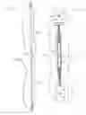
FIG. 1A contains a full front view of the brace when expanded, comprising hinge “a”.
FIG. 1B contains a full front view of the brace when contracted, comprising hinge “a”.
FIG. 1C shows a top view of hinge plate “a”.
FIG. 1D shows a front view of the “T” bolt.
FIG. 1E shows a front view of completed hinge “a”.
FIG. 1F shows a side view of completed hinge “a”
FIG. 1G demonstrates a side view of the hinge rotation.
FIG. 2A shows a full front view of the brace when expanded, comprising hinge “b”.
FIG. 2B shows a full front view of the brace when contracted, comprising hinge “b”.
FIG. 2C shows a top view of hinge plate “b”.
FIG. 2D shows a full front view of the “J” bolt.
FIG. 2E shows a front view of completed hinge “b”
FIG. 2F demonstrates a side view of hinge rotation
FIG. 3A shows the smaller telescoping tube, washer and nut.
FIG. 3B shows an end view of the smaller telescoping tube washer and nut weld.
FIG. 3C shows the larger telescoping tube, washer and nut.
FIG. 3D shows an end view of the larger telescoping extension tube washer and nut weld.
FIG. 4A shows the optional extension bar.
REFERENCE NUMBERS IN DRAWINGS
- 20 Flat hinge page “a”
- 21 Small fastener hole
- 22 Large fastener hole
- 23 Hinge “a” pivot point
- 24 Hinge Wrap/Female hinge port “a”
- 25 Solid rod
- 26 Right thread rod
- 27 Left thread rod
- 28 Solid rod to thread rod weld
- 29 Completed “T” bolt
- 30 Completed right hand hinge “a”
- 31 Completed left hand hinge “a”
- 40 Flat hinge plate “b”
- 41 Hinge “b” pivot point
- 42 Hollow pipe/Female hinge port “b”
- 43 90-degree bolt bend
- 44 180-degree bolt bend
- 45 Securing bolt
- 46 Securing bolt threads
- 47 Completed “J” bolt
- 48 “J” bolt with nut
- 50 Completed right hand hinge “b”
- 51 Completed left hand hinge “b”
- 70 Smaller Diameter Tubing
- 71 Right thread hexogen nut
- 72 USS washer
- 73 USS nut to washer weld
- 74 Right thread nut to USS washer weld
- 75 USS washer to tubing weld
- 79 Completed right thread bracing bar
- 80 Larger diameter tubing
- 81 Left thread hexogen nut
- 82 SAE washer
- 83 SAE nut to washer weld
- 84 Left thread nut to SAE washer weld
- 85 SAE washer to tubing weld
- 89 Completed left thread bracing bar
- 90 Adjusting holes
- 91 Securing hole
- 92 Securing clip, bolt or screw
- 98 Completed bracing bar with hinge “a”
- 99 Completed bracing bar with hinge “b”
- 100 Extension bar
FIGS. 1A, 1B, 1C-1F, 2A, 2B, 2C-2F, 3A-3D, 4A
The preferred embodiment of the present invention is illustrated in the above drawing figs, most completely in FIG. 1A-1B and FIG. 2A-2B. Keeping in mind the described components can be of varying size, dimension, and shape. So as not to limit the possible scope of this invention but only to create a more clear understanding to the reader, I will describe the materials needed to construct a metal brace 6′ in length which extends to 12′ in length constructed of square tubing and the respective components to produce a unit of this size. This size brace would support and level a standard 8′-12′ wall. When adding one extension bar, this brace would support and level a standard 20′ wall.
FIG. 1A-1B, FIG. 2A-2B and FIG. 3A-3D Bracing Bars
As the bracing components of FIGS. 1A-B and 2A-B are virtually one in the same, for the purpose of this description, I will refer only to FIGS. 1A and 1B.
A brace portion FIG. 1A-1B is constructed of one 5′10″ length of 1¼″×1¼″×0.065 square metal tubing 80 and one 5′10″ length of 1″×1″×0.083 square metal tubing 70.
FIGS. 3A-3D: nuts 71 and 81 and washers 72 and 82 are welded at one end of each piece of square tubing. FIG. 3B: a ½″ right thread hexogen nut 71 is welded 73 to a USS washer 72. FIG. 3B: USS washer 72 is then welded 74 to the end of the 1″×1″×0.083 square tubing 70. FIG. 3C: a ½″ left thread hexogen nut 81 is welded 83 to a SAE washer 82. FIG. 3D: SAE washer 82 is then welded 84 to the end of 1¼″×1¼″×0.065 square metal tubing 80.
FIG. 1B: adjusting holes 90 are drilled at varying lengths through the 1″×1″×0.083 square tubing 70. A securing hole 91 is drilled through the 1¼″×1¼″×0.065 square tubing 80. Holes allow the securing clip 92 to hold the brace at the desired length. Completed right thread bracing bar now referenced as 79. Completed left thread bracing bar now referenced as 89. Completed bars may now be painted.
FIG. 1A-1G Right and Left Hand Thread Hinge Units “a”
A hinge pictured in FIG. 1A and FIG. 1B, is constructed of the following elements as shown in FIGS. 1C, 1D, and 1E. FIG. 1C a 3″×6″ plate 20 is cut from ⅛″×3″ metal flat bar. A ½″×1″ retangle 23 is removed from one end of the plate with a plasma cutter. This notch out forms the pivot point 23 and wrapped portion of female hinge port 24.
FIG. 1C: four or more ⅛″ securing holes 21 are drilled down both sides of the metal plate 20 no more than ⅛″ from edge of plate 20 and no more than ¼″ from female hinge port 24. FIG. 1C: a hole the circumference of a standard metal stake (¾″) 22 is drilled in the center of metal plate 20.
FIG. 1D: a “T” bolt 29 is constructed by welding a ½″×3″ solid bolt 25 to an 8″ Left Hand all thread rod 27. Solid bolt 25 is welded centered and perpendicular 28 to thread rod 27 thus forming a “T” 29. Completed “T” bolt unit now referenced as 29.
FIG. 1E: “T” bolt 29 is placed at notched end of flat metal plate 20. FIG. 1C: top two sections of metal plate 24 are wrapped around “T” bolt 29 and welded in place, thus forming a female hinge port and male hinge assembly FIGS. 1E-1F completing left thread hinge unit “a”. Repeat process utilizing an 8″ Right Hand all thread rod 26 to construct right hand thread hinge unit 31. Right and Left thread hinge units 30, 31 are stamped with corresponding letters or painted for later identification during assembly. Completed left thread hinge unit “a” now referenced as 30. Completed right thread hinge unit “a” now referenced as 31.
FIG. 1G demonstrates the 300° turning radius of hinge “a” 30 and 31.
Right and left thread hinge units 30 and 31 are screwed into right and left thread tubing 70 and 80 respectively. Smaller tubing section 70 is inserted into larger tubing section 80 completing bracing bar FIG. 1A. A removable clip, bolt or screw 92 may now be placed through the securing hole. Completed brace with hinge “a” 98 shown fully extended in FIG. 1A. Completed brace with hinge “a” 98 shown fully collapsed in FIG. 1B.
Additional EmbodimentsFIG.2A-2F Alternate Hinge “b”, FIG. 4A Extension Bar
Alternate hinge “b” FIG. 2A-2F is constructed in much the same manner as hinge “a” 30 and 31. FIG. 2C shows flat hinge plate “b” 40 containing wrapped female hinge port 42 thereby allowing pivot point 41 and 300° rotation demonstrated in FIG. 2F.
FIG. 2D alternate hinge “b” is characterized by use of a “J” shaped bolt 47. The “J” shaped thread rod bolt 47 is formed by pressing a 13″ partially threaded and partially solid bolt into a dye which forms a 90° bend 43 at base of 6″ thread portion and curving continuously into a 180° opposing bend 44 thus forming a “J”. FIG. 2E: the “J” bolt 47 is placed into female hinge port 42 and secured by screwing left or right thread nut 45 onto the ½″ of securing nut threads 46. Completed right and left hand hinge “b” now referenced as 50 and 51.
Completed brace with hinge “b” 99 shown fully extended in FIG. 2A. Completed brace with hinge “b” 99 shown fully contracted in FIG. 2B.
Optional extension bar FIG. 4A allows 12′ brace to be extended another 4′-6′100.
Operation
To lift and level a wall with the described support and plumb brace, hinge unit 30, 31, 50 or 51 is placed at the top board of frame wall and secured with screws through the small fastener holes 21. The bracing unit 98 or 99 is adjusted to the desired length and secured by placing a securing clip 92 simultaneously through securing and adjusting holes 90 and 91 thereby holding the two bracing unit sections 70 and 80 at the desired length. The hinge unit at the opposing end 30,31, 50 or 51 is attached to the ground surface. This now provides bracing support to the fame wall. The frame wall can then be pushed or pulled into level or plumb position by simply turning the bracing unit 98 or 99 in either a clockwise or counter clockwise direction. Since the threaded rods 26 and 27 at each end of the hinge unit 30, 31, 50, or 51 are threaded in opposing directions, they become longer or shorter simultaneously. Therefore, by turning the square tubing sections of the brace 70 and 80 clockwise the brace becomes longer pushing the surfaces apart. When turning the square tubing sections of the brace 70 and 80 counter clockwise it becomes shorter pulling the surfaces together.
CONCLUSION, RAMIFICATIONS, & SCOPEAccordingly, the reader will see that the wall support and plumb brace of this invention can be used to brace and level walls much faster and easier than the old fashioned lumber method. The extension bars and bracing unit are easy to transport and store. Further, by saving lumber waster, this brace will help to preserve our natural resources and save the builder time and materials costs. A number of other advantages include.
-
- (a) Fewer accidents on the job sight.
- (b) Easy attachment to many surfaces.
- (c) One person can level a surface without help.
- (d) Unstable buildings can be supported while being repaired.
- (e) Setting roof trusses is easier and faster.
- (f) Leaning walls can be pulled together.
The presently described dimensions and materials for making and using the support and plumb brace have been directed to the field of wood frame building construction. However, this bracing unit has many other possibilities. Thus, the scope of the invention should be determined by the attached claims.
Claims
I claim:1. An adjustable wall anchoring and straightening device comprising:
telescoping tube bars which subsequently slide into and out of one another thus providing said bar to be lengthened or shortened;
hinged end members comprising opposing directional thread rods thereby allowing simultaneous extension or contraction;
adjusting holes in said telescoping tube bars for securing length adjustment;
multi sized securing holes in said hinged members for earth, wood, and concrete securing.
2. The adjustable wall anchoring and straightening device as defined in claim 1 wherein hinged members are equipped with at least one hole specifically designed the size and circumference to accept a standard concrete stake.
3. The adjustable wall anchoring and straightening device as defined in claim 1 wherein telescoping tube bars are equipped with thread rod acceptors thereby allowing thread rod acceptance and adjustment.
4. The adjustable wall anchoring and straightening device as defined in claim 1 wherein the hinged members are characterized by securing holes of varying sizes thereby allowing acceptance of securing devices of varying sizes.
5. The adjustable wall anchoring and straightening device as defined in claim 1 wherein telescoping members may accept an extension device.
6. The adjustable wall anchoring and straightening device as defined in claim 1 wherein optional threaded attachments may be added enabling additional uses of said telescoping members.
7. The adjustable wall anchoring and straightening device as defined in claim 1 wherein the hinged members are characterized by the use of a “T” shaped threaded and/or solid rod bolt.
8. The adjustable wall anchoring and straightening device as defined in claim 1 wherein the hinged members are characterized by the use of a “J” shaped threaded and/or solid rod bolt.
9. The adjustable wall anchoring and straightening device as defined in claim 1 wherein telescoping bars are painted and/or powdered coated a bright color.
10. The adjustable wall anchoring and straightening device as defined in claim 1 wherein telescoping bar members are comprised of square tubing.
11. The adjustable wall anchoring and straightening device as defined in claim 1 wherein telescoping bar members are comprised of round tubing.
12. The adjustable wall anchoring and straightening device as defined in claim 1 wherein telescoping bar members are comprised of various geometric shaped tubing.
13. The adjustable wall anchoring and straightening device as defined in claim 1 wherein the hinged members are characterized by a flat hinge plate with continuous wrapped female hinge port.
Images & Drawings included:


Sources:
- United States Patent and Trademark Office - verify current appl. status at the USPTO↗
Recent applications in this class:
- » 20230399862 2023-12-14
TRUSS SUPPORT SYSTEM - » 20230075809 2023-03-09
Push-pull prop - » 20220112733 2022-04-14
Formwork systems and related methods - » 20180058082 2018-03-01
GROUND ANCHOR BRACKET FOR MULTIPLE WALL BRACES - » 20170009474 2017-01-12
Pole clamp system for partition mount - » 20120068036 2012-03-22
PRESSURE-APPLYING TELESCOPIC SPACER - » 20110173918 2011-07-21
ADJUSTABLE WALL BRACE - » 20110079698 2011-04-07
BRACE - » 20110068568 2011-03-24
Pressure-applying telescopic spacer - » 20110047895 2011-03-03
Tilt-up wall brace dolly and method of use