Flexible production process for fabricating heat pipes
US20060096095A1
2006-05-11
10/984,437
2004-11-10
✅ Patent granted
US 7,467,465 B2
2008-12-23
-
-
David P. Bryant | Sarang Afzali
2026-11-26
Abstract:
A flexible production process for fabricating a heat pipe, having the processes of (a) performing pre-process on a heat-pipe material, (b) performing annealing process on the heat-pipe material, (c) introducing working fluid into the heat-pipe material, (d) removing non-condensable gas from the heat-pipe material, and (e) sealing the openings of the heat-pipe material. The heat-pipe material can be disposed into a laminar flow box between any of the steps (a) and (b), (b) and (c), and (c) and (d).
Inventors:
- Jia-Hao Li 11 🇹🇼 Kao Hsiung Hsien, Taiwan
- Jia-Hao Li 5 🇹🇼 Kang Shan Jen, Kao Hsiung Hsien, Taiwan
Interested in similar patents?
Get notified when new applications in this technology area are published.
Classification:
B21D53/06 IPC
Making other particular articles heat exchangers , e.g. radiators, condensers of metal tubes
B23P15/26 » CPC main
Making specific metal objects by operations not covered by a single other subclass or a group in this subclass heat exchangers or the like
F28D15/0283 » CPC further
Heat-exchange apparatus with the intermediate heat-transfer medium in closed tubes passing into or through the conduit walls ; Heat-exchange apparatus employing intermediate heat-transfer medium or bodies in which the medium condenses and evaporates, e.g. heat pipes Means for filling or sealing heat pipes
Y10T29/49353 » CPC further
Metal working; Method of mechanical manufacture; Heat exchanger or boiler making Heat pipe device making
Y10T29/49377 » CPC further
Metal working; Method of mechanical manufacture; Heat exchanger or boiler making Tube with heat transfer means
Y10T29/49391 » CPC further
Metal working; Method of mechanical manufacture; Heat exchanger or boiler making Tube making or reforming
Y10T29/49808 » CPC further
Metal working; Method of mechanical manufacture Shaping container end to encapsulate material
Y10T29/53096 » CPC further
Metal working; Means to assemble or disassemble including means to provide a controlled environment
B23P6/00 IPC
Restoring or reconditioning objects
Description
BACKGROUND OF THE INVENTIONThe present invention relates in general to a flexible production process for fabricating a heat pipe, and more particularly, to a flexible production process that allows production of heat pipe to be resumed after temporary or over-night off of the production line.
In the typical fabrication process of heat pipes, processes such as cleaning, annealing, filling of working fluid, removal of non-condensable gas are required in a dust-proof chamber. Therefore, when the production line is temporary or overnight off, the heat pipes under process will not be exposed to air. Otherwise, the heap pipes have to be fabricated without interruption.
However, factors may affect the normal operation of the production line can hardly be controlled, dustproof rooms are typically built for heat-pipe manufactures. However, the dustproof rooms are very expensive, and it costs a lot to control the allowable members entering the dustproof rooms. Therefore, the cost of heat pipes cannot be reduced.
BRIEF SUMMARY OF THE INVENTIONTo resolve the above drawbacks, a flexible production process for fabricating heat pipes is provided. Such process does not require a dustproof room, while the heat pipes are prevented from being contaminated by air due to temporary or overnight off of the machines. The fabrication can thus be resumed after the production line is open again.
Accordingly, the flexible production process for fabricating heat pipes includes the processes of (a) performing pre-process on a heat-pipe material, (b) performing annealing process on the heat-pipe material, (c) introducing working fluid into the heat-pipe material, (d) removing non-condensable gas from the heat-pipe material, and (e) sealing the openings of the heat-pipe material. The heat-pipe material can be disposed into a laminar flow box between any of the steps (a) and (b), (b) and (c), and (c) and (d).
BRIEF DESCRIPTION OF THE DRAWINGSThe above objects and advantages of the present invention will be become more apparent by describing in detail exemplary embodiments thereof with reference to the attached drawings in which:
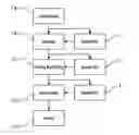
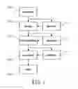
FIG. 1 shows an a fabrication process of heat pipes; and
FIG. 2 shows the application status of a laminar box.
DETAILED DESCRIPTION OF THE INVENTIONReferring to FIGS. 1 and 2, a flexible production process is provided to allow temporary or overnight off of a production line of heat pipes without the requirement of a dustproof room, while the heat pipes are prevented from being contaminated by air. In this process, laminar boxes 1, 1′ and 1″ are adequately used in various fabrication steps of the heat pipes 2.
The production process (a) includes a pre-process, which perform pre-process on heat-pipe material 2, including checking whether the tubular material and the wick structure meets with the standard requirement, disposing the wick structure into the tubular material of the heat pipe, and cutting the tubular material into a desired length, and a cleaning the tubular material.
After the pre-process, an annealing process (b) is performed to the tubular material to suppress the stress in the tubular material, prevent the tubular material from being oxidized, and further clean the tubular material.
An adequate amount of working fluid is then introduced into the tubular material to work as a phase transition medium in step (c).
The non-condensable gas in the tubular material is then removed in step (d).
The openings of the tubular material are then sealed in step (e).
During the above process steps, for example, between steps (a) and (b), (b) and (c) or (c) and (d), the tubular materials are disposed in laminar boxes 1, 1′ and 1″ as shown in FIG. 2. The laminar box 1 includes a hollow deposit chamber 100 and a deposit platform in the deposit chamber 100 allowing semi-products of the unfinished heat pipes 2 to be disposed therein. One side of the deposit chamber 100 includes a door panel 102 for accessing the heat pipes 2, and a gas supply 11 is installed on top of the laminar box 1. The gas supply 11 provides protection gas to protect the unfinished heat pipes 2. A plurality of flow diffluent device installed at the top of the laminar box 10 is connected to the gas supply to deliver the gas to a first fairing device 13 to direct the gas flowing vertically downward to the deposit chamber, such that the unfinished heat pipes 2 can be preserved in a clean air environment. Under the deposit platform 101 is a partitioning board 14. The partitioning board 14 includes a plurality of through holes allowing the gas to flow through. The laminar box 10 further includes a second fairing device 15 to exhaust the air carrying impurity out of the chamber 100.
Accordingly, when the fabrication of the heat pipes 2 have to be interruption between steps (a) and (b), (b) and (c), or (c) and (d) due to unexpected condition, the unfinished heat pipes 2 can be stored or deposited in the laminar boxes 1, 1′ and 1″. Thereby, the interruption of fabrication will not cause any contamination upon the unfinished heat pipes 2.
While the present invention has been particularly shown and described with reference to preferred embodiments thereof, it will be understood by those of ordinary skill in the art the various changes in form and details may be made therein without departing from the spirit and scope of the present invention as defined by the appended claims.
Claims
What is claimed is:1. A flexible production process for fabricating heat pipes, comprising:
(a) performing pre-process on tubular materials for making heat pipes;
(b) performing annealing process on the tubular materials;
(c) filling working fluid in the tubular material;
(d) removing non-condensable gas from the tubular materials; and
(e) sealing openings of the tubular materials; wherein the tubular members are disposed in laminar boxes when the process is interrupted between steps of (a) and (b), (b) and (c), or (c) and (d).
2. The process of claim 1, wherein step (a) checks whether the tubular materials, wick structures in the tubular materials meet with standard and cuts the tubular material into required lengths.
Images & Drawings included:

Sources:
- United States Patent and Trademark Office - verify current appl. status at the USPTO↗
Recent applications in this class:
- » 20250205836 2025-06-26
METHOD FOR MANUFACTURING HEAT EXCHANGER - » 20250205835 2025-06-26
METHOD FOR MANUFACTURING A HEAT EXCHANGER BY BRAZING A TEMPERATURE PROBE, CORRESPONDING HEAT EXCHANGER AND TEMPERATURE PROBE - » 20250196276 2025-06-19
DISASSEMBLY METHOD FOR TWO-STAGE COLD HEAD, AND DISPLACER REMOVAL JIG - » 20250196275 2025-06-19
METHOD FOR USING HEAT DISSIPATION PLATE MANUFACTURING APPARATUS - » 20250187124 2025-06-12
AIR COOLED CONDENSER AND RELATED METHODS - » 20250178140 2025-06-05
Window Installation System And Method For Split-Architecture Air Conditioning Unit - » 20250153287 2025-05-15
HEAT TRANSFER SHEET, METHOD FOR PRODUCING HEAT TRANSFER SHEET, HEAT TRANSFER SHEET PACKAGE, AND METHOD FOR PRODUCING HEAT TRANSFER SHEET PACKAGE - » 20250144754 2025-05-08
TIGHT-FIT RIVETING PROCESS FOR HEAT DISSIPATION ALUMINUM PLATE AND HEAT PIPE - » 20250065453 2025-02-27
HEAT EXCHANGER PROCESSING METHOD AND HEAT EXCHANGER PROCESSING APPARATUS - » 20250018511 2025-01-16
MANUFACTURING DEVICE AND MANUFACTURING METHOD FOR HEAT EXCHANGER AND TRANSPORT CARRIAGE USED FOR MANUFACTURING DEVICE