Golf stand bag
US20060108244A1
2006-05-25
11/086,696
2005-03-22
Abstract:
A golf stand bag of the present invention comprises a bottom; a top; and two stays; wherein each of the two stays is connected with the bottom and the top at its two ends; one stay connecting with the top in an inner side adjacent to a side top end thereof and the other stay connecting with the top in an inner side far from the side top end thereof. The two stays have their axes in a same plane and there is a certain angle between their axes so as to prevent the bottom from rotating relative to the top.
Interested in similar patents?
Get notified when new applications in this technology area are published.
Classification:
A63B55/50 » CPC further
Bags for golf clubs; Stands for golf clubs for use on the course; Wheeled carriers specially adapted for golf bags Supports, e.g. with devices for anchoring to the ground
A63B55/00 » CPC main
Bags for golf clubs; Stands for golf clubs for use on the course; Wheeled carriers specially adapted for golf bags
Description
FIELD OF THE INVENTIONThe present invention is related to golf game apparatus, and particularly to a golf stand bag which top and bottom do not rotate relatively so as to attain a high stability.
BACKGROUND OF THE INVENTIONAt present, a traditional golf stand bag comprises a top 2 and a bottom 1 which has a connection and support structure, as shown in FIG. 1. A stay 3 connects the top 2 with the bottom 1 at a top inside thereof far from a slantwise-supporting apparatus of the golf stand bag (not shown). Because of the connections between the stay 3, the top 2 and the bottom 1 is a fixed connection, the stay 3 then makes a small bottom 12 of the bottom 1 rotate relatively to a big bottom 11 of the bottom 1 when the golf stand bag is positioned slantways by the slantwise-supporting apparatus. Then, the big bottom 11 contacts with the ground while the small bottom 12 is off the ground so as to make the golf stand bag stand stably with the help of the big bottom 11 and the slantwise-supporting apparatus. However, because there is only one stay to connect the bottom 1 with the top 2, the bottom 1 and the top 2 are easily rorated relatively with the axis of the stay 3 as rotation axis. This will reduce the reliability and usage life of the golf stand bag, and also degrade the support stability thereof.
Hence it is desired to provide a golf stand bag which can overcome the foregoing drawbacks of the prior art.
SUMMARY OF THE INVENTIONA main object of the present invention is to provide a golf stand bag which has a high stability and make sure no relative rotation will happen between a top and a bottom of the golf stand bag.
A golf stand bag of the present invention comprises a bottom, a top, and two stays; wherein each of the two stays is connected with the bottom and the top at its two ends; one stay connecting with the top in an inner side adjacent to a side top end thereof and the other stay connecting with the top in an inner side far from the side top end thereof.
In an embodiment, the two stays have their axes in a same plane and there is a certain angle between their axes. The bottom has a bottom constituted with a big bottom and a small bottom which are connected together by an elastic connection portion. Each stay has a bottom end connected with an inner side of a sidewall of the bottom, one is connected at a position near to a top end of the small bottom while the other is connected at a position adjacent to the elastic connection portion. In an embodiment, the elastic connection portion is U-shaped.
Because the golf stand bag of the present invention has two stays to connect the bottom with the top, which is positioned in a same plane, Thus preventing the bottom from rotating relative to the top and prolonging the usage life of the golf stand bag. In addition, connection positions of the two stays connecting with the bottom or the top has a long distance so that the force-bearing points thereon has a long distance and thus a stable support of the golf stand bag is attained.
For the purpose of making the invention easier to understand, some particular embodiments thereof will now be described with reference to the appended drawings in which:
DESCRIPTION OF THE DRAWINGSFIG. 1 is a sketch of showing a connection structure between a bottom and a top of a traditional golf stand bag;
FIG. 2 is a sketch of showing a connection structure between a bottom and a top of a golf stand bag of the present invention;
FIG. 3 is a sketch of showing a positional relation between two stays of the present invention;
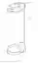
FIG. 4 is a perspective view of a golf stand bag according to an embodiment of the present invention.
DETAILED DESCRIPTION OF THE INVENTIONReferring now to the drawings in detail, as shown in FIGS. 2-3, according to an embodiment of the present invention, a golf stand bag comprises a bottom 1′, a top 2′ and two stays 3′. Each of the two stays 3′ are connected with the bottom 1′ and the top 2′ at its two ends. The two stays 3′ have their axes in a same plane and there is a certain angle between their axes. The bottom of the bottom 1′ comprises a big bottom 11 and a small bottom 12 which are connected together by an U-shaped elastic connection portion 15. Each of the two stays 3′ is connected with the bottom 1′ and the top 2′ at its two ends. The top end of each stay 3′ is connected with an inner side of the top 2′, and the connection positions thereof exist a certain distance, that is, one stay 3′ connecting with the top 2′ in an inner side adjacent to a side top end thereof and the other stay 3′ connecting with the top 2′ in an inner side far from the side top end thereof. The bottom end of each stay 3′ is connected with an inner side of a sidewall 13 of the bottom 1′, one is connected at a position near to a top end of the small bottom 12 while the other is connected at a position adjacent to the elastic connection portion 15.
Referring to FIGS. 2 and 4, during using the golf stand bag, it is only to tilt the golf stand bag forwardly, and then the elastic connection portion 15 of the bottom 1′ is compressed under the press exerted by the stay 3′ so as to make the big bottom 11 of the bottom 1′ still contact with the ground, while the small bottom 12 rotates around the connection portion 15 and then leaving from the ground and forming a certain angle with the ground. In the meantime, a foot bracket 5 of the golf stand bag is unfolded so as to make the golf stand bag stand slantways. Because the two unparallel stays 3′ are positioned at a same plane so as to not only make the golf stand bag stand stable and no rotation will happen between the bottom 1′ and the top 2′. When lifting the golf stand bag, the elastic connection portion 15 will return to its original shape and the small and big bottoms 12, 11 will also return back to their original positions. Then the foot bracket 5 will also draw back under an effort of a pair of steel wires 4.
It is understood that the invention may be embodied in other forms without departing from the spirit thereof. Thus, the present examples and embodiments are to be considered in all respects as illustrative and not restrictive, and the invention is not to be limited to the details given herein.
Claims
What is claimed is:1. A golf stand bag comprising:
a bottom;
a top; and
two stays; wherein each of the two stays is connected with the bottom and the top at its two ends; one stay connecting with the top in an inner side adjacent to a side top end thereof and the other stay connecting with the top in an inner side far from the side top end thereof.
2. The golf stand bag as claimed in claim 1, wherein the two stays have their axes in a same plane and there is a certain angle between their axes.
3. The golf stand bag as claimed in claim 2, wherein the bottom has a bottom constituted with a big bottom and a small bottom which are connected together by an elastic connection portion.
4. The golf stand bag as claimed in claim 3, wherein each stay has a bottom end connected with an inner side of a sidewall of the bottom, one is connected at a position near to a top end of the small bottom while the other is connected at a position adjacent to the elastic connection portion.
5. The golf stand bag as claimed in claim 3, wherein the elastic connection portion is U-shaped.
Images & Drawings included:


Sources:
- United States Patent and Trademark Office - verify current appl. status at the USPTO↗
Similar patent applications:
- » 20110005949
Rotate bottom base assembly for a golf stand bag and golf stand bag with a rotate bottom base assembly - » 20090212174
Golf Bag Stand System - » 20100140122
Golf bag stand - » 20070068829
Golf stand bag - » 20100252466
Stand golf bag with mechanism to secure clubs - » 20080078913
Adjustable golf bag stand - » 20080169212
Golf bag stand - » 20080217195
Stand golf bag with mechanism to secure clubs - » 20080251399
Golf stand bag having folding body - » 20120074269
Adjustable golf bag stand
Recent applications in this class:
- » 20230356046 2023-11-09
Golf club tracking assembly - » 20210093936 2021-04-01
DETACHABLE COMBINED CHASSIS STRUCTURE OF GOLF BAG - » 20160184674 2016-06-30
Golf club shaft protector - » 20160016058 2016-01-21
SYSTEM AND METHOD FOR A VERTICALLY CARRIED GOLF BAG - » 20150209632 2015-07-30
GOLF BAG ASSEMBLY STRUCTURE - » 20150122678 2015-05-07
Modular golf bag and method of making same - » 20150114859 2015-04-30
GOLF BAGS WITH A DETACHABLE CARRYING STRAP SYSTEM AND METHODS TO MANUFACTURE GOLF BAGS WITH A CARRYING STRAP SYSTEM - » 20150076019 2015-03-19
HEAD FRAME OF GOLF BAG - » 20150068932 2015-03-12
GOLF BAG WITH A CRADLE FOR A MOBILE DEVICE - » 20150014196 2015-01-15
Golf bag divider accessory and method of making same