Plastic panel
US20060144014A1
2006-07-06
11/325,866
2006-01-05
Abstract:
The present invention relates to a plastic panel, and more particularly, to a plastic panel which comprises inner and outer panels wherein a bonding groove to be coated with an adhesive is formed on any one of the inner and outer panels. According to a preferred embodiment of the present invention, the bonding groove is formed on any one of the inner and outer panels, while a protrusion is formed on a bonding surface of the other of the inner and outer panels. Accordingly, since the bonding groove is bonded to the bonding surface of the inner or outer panel, the bonding groove can serve as a guide when the adhesive is applied. Thus, the adhesive can be applied at a uniform thickness to correct positions even though it is manually applied, and even an adhesive with certain fluidity can be prevented from leaking to the outside. Therefore, there are advantages in that the post-processing work for enhancing the external appearance is not required, the manufacturing time and costs can be reduced, and the bonding force can be increased due to the increased bonding area.
Inventors:
- Hee-Deog Kim 5 🇰🇷 Seoul, South Korea
- Hyung-Jun Ahn 2 🇰🇷 Daejeon-si, South Korea
- In-Se Yoon 2 🇰🇷 Daegu-si, South Korea
Interested in similar patents?
Get notified when new applications in this technology area are published.
Classification:
B29C65/48 » CPC main
Joining of preformed parts ; Apparatus therefor using adhesives, i.e. using supplementary joining material; solvent bonding
B29C66/112 » CPC further
General aspects of processes or apparatus for joining preformed parts; General aspects dealing with the joint area or with the area to be joined; Particular design of joint configurations particular design of the joint cross-sections; Joint cross-sections comprising a single joint-segment, i.e. one of the parts to be joined comprising a single joint-segment in the joint cross-section Single lapped joints
B29C66/1122 » CPC further
General aspects of processes or apparatus for joining preformed parts; General aspects dealing with the joint area or with the area to be joined; Particular design of joint configurations particular design of the joint cross-sections; Joint cross-sections comprising a single joint-segment, i.e. one of the parts to be joined comprising a single joint-segment in the joint cross-section; Single lapped joints Single lap to lap joints, i.e. overlap joints
B29C66/114 » CPC further
General aspects of processes or apparatus for joining preformed parts; General aspects dealing with the joint area or with the area to be joined; Particular design of joint configurations particular design of the joint cross-sections; Joint cross-sections comprising a single joint-segment, i.e. one of the parts to be joined comprising a single joint-segment in the joint cross-section Single butt joints
B29C66/1284 » CPC further
General aspects of processes or apparatus for joining preformed parts; General aspects dealing with the joint area or with the area to be joined; Particular design of joint configurations particular design of the joint cross-sections; Joint cross-sections combining only two joint-segments; Tongue and groove joints; Tenon and mortise joints; Stepped joint cross-sections; Stepped joint cross-sections comprising at least one butt joint-segment
B29C66/1286 » CPC further
General aspects of processes or apparatus for joining preformed parts; General aspects dealing with the joint area or with the area to be joined; Particular design of joint configurations particular design of the joint cross-sections; Joint cross-sections combining only two joint-segments; Tongue and groove joints; Tenon and mortise joints; Stepped joint cross-sections; Stepped joint cross-sections comprising at least one bevelled joint-segment
B29C66/322 » CPC further
General aspects of processes or apparatus for joining preformed parts; General aspects dealing with the joint area or with the area to be joined; Measures for keeping the burr form under control; Avoiding burr formation; Shaping the burr Providing cavities in the joined article to collect the burr
B29C66/54 » CPC further
General aspects of processes or apparatus for joining preformed parts; General aspects of joining tubular articles; General aspects of joining long products, i.e. bars or profiled elements; General aspects of joining single elements to tubular articles, hollow articles or bars; General aspects of joining several hollow-preforms to form hollow or tubular articles; Joining tubular articles, profiled elements or bars; Joining single elements to tubular articles, hollow articles or bars; Joining several hollow-preforms to form hollow or tubular articles Joining several hollow-preforms, e.g. half-shells, to form hollow articles, e.g. for making balls, containers; Joining several hollow-preforms, e.g. half-cylinders, to form tubular articles
B62D27/026 » CPC further
Connections between superstructure sub-units rigid Connections by glue bonding
B62D29/04 » CPC further
Superstructures, characterised by the material thereof predominantly of synthetic material
E04C2/20 » CPC further
Building elements of relatively thin form for the construction of parts of buildings, e.g. sheet materials, slabs, or panels characterised by specified materials of wood, fibres, chips, vegetable stems, or the like; of plastics; of foamed products of plastics
B29C65/7829 » CPC further
Joining of preformed parts ; Apparatus therefor; Means for handling the parts to be joined, e.g. for making containers or hollow articles, e.g. means for handling sheets, plates, web-like materials, tubular articles, hollow articles or elements to be joined therewith; Means for discharging the joined articles from the joining apparatus; Positioning the parts to be joined, e.g. aligning, indexing or centring by setting the gap between the parts to be joined by using distance pieces, i.e. by using spacers positioned between the parts to be joined and forming a part of the joint said distance pieces being integral with at least one of the parts to be joined
B29L2024/00 » CPC further
Articles with hollow walls
B29L2031/3055 » CPC further
Other particular articles; Vehicles, e.g. ships or aircraft, or body parts thereof Cars
B29L2031/724 » CPC further
Other particular articles Doors
B29C65/7814 » CPC further
Joining of preformed parts ; Apparatus therefor; Means for handling the parts to be joined, e.g. for making containers or hollow articles, e.g. means for handling sheets, plates, web-like materials, tubular articles, hollow articles or elements to be joined therewith; Means for discharging the joined articles from the joining apparatus; Positioning the parts to be joined, e.g. aligning, indexing or centring the parts to be joined comprising positioning features in the form of inter-cooperating positioning features , e.g. tenons and mortises
B29C66/128 » CPC further
General aspects of processes or apparatus for joining preformed parts; General aspects dealing with the joint area or with the area to be joined; Particular design of joint configurations particular design of the joint cross-sections; Joint cross-sections combining only two joint-segments; Tongue and groove joints; Tenon and mortise joints; Stepped joint cross-sections Stepped joint cross-sections
B29C66/30321 » CPC further
General aspects of processes or apparatus for joining preformed parts; General aspects dealing with the joint area or with the area to be joined; Particular design of joint configurations the joint involving an anchoring effect making use of protusions or cavities belonging to at least one of the parts to be joined making use of protusions belonging to at least one of the parts to be joined
B29C65/00 » CPC further
Joining of preformed parts ; Apparatus therefor
B29K2067/003 » CPC further
Use of polyesters or derivatives thereof , as moulding material PET, i.e. poylethylene terephthalate
B29K2069/00 » CPC further
Use of PC, i.e. polycarbonates or derivatives thereof , as moulding material
B29C66/71 » CPC further
General aspects of processes or apparatus for joining preformed parts characterised by the composition, physical properties or the structure of the material of the parts to be joined; Joining with non-plastics material characterised by the composition of the plastics material of the parts to be joined
E04C2/54 IPC
Building elements of relatively thin form for the construction of parts of buildings, e.g. sheet materials, slabs, or panels Slab-like translucent elements
Description
TECHNICAL FIELDThe present invention relates to a plastic panel, and more particularly, to a plastic panel which comprises inner and outer panels wherein a bonding groove to be coated with an adhesive is formed on any one of the inner and outer panels.
BACKGROUND ARTIn general, a panel is made of a single plate. However, in the case of a vehicle door in which it is necessary to contain some articles, two panels, i.e. an inner panel and an outer panel, are bonded to each other in order to contain the necessary articles between the inner and outer panels. In particular, a bonded panel composed of inner and outer panels is typically used as a tail gate of a vehicle. Members for opening/closing and locking a door, members for operating a wiper and a variety of reinforcing members for installing the wiper and aforementioned members are provided in the vehicle tail gate. For example, a hinge used for opening/closing the door and a hinge reinforcement thereof are provided at an upper end of the tail gate; a space for installing a wiper motor of a wiper system and a wiper motor bracket thereof are provided at the center of a lower portion of the vehicle tail gate; and a latch bracket used for mounting a latch for opening/closing the tail gate is also provided at the center of a lower end of the tail gate. Accordingly, bonding surfaces are generally formed along an edge of the inner and outer panels between which a space is thus formed.
The inner and outer panels of the vehicle tail gate are generally manufactured from a steel sheet. In such a case, however, the two steel sheets should be joined and assembled through a spot welding method, and thus, a thickness of the steel sheet should be increased up to a certain thickness. Therefore, this leads to the increase of overall weight and production costs of the tail gate. Accordingly, the steel sheet for use in the tail gate has been recently replaced with a plastic sheet.
In the case of the plastic panel, such as the vehicle tail gate, manufactured by coupling two inner and outer panels with each other, the inner and outer panels are bonded and assembled with each other using the conventional adhesive. Since the bonding surface of the currently available inner and outer panels is planar (See FIG. 2), there is a problem in that the used adhesive leaks out of the bonded panels. In particular, since the adhesive is applied onto the planar bonding surface, the adhesive, if it has certain fluidity, inevitably leaks out from the panels after applied on the bonding surface. This problem can occur when the adhesive is manually applied and also even when an accurate amount of adhesive is applied by using adhesive coating equipment.
Accordingly, the adhesive is excessively spent more than is necessary and an additional process for removing the adhesive leaked between the inner and outer panels is required. Consequently, there are some problems that it takes a long time to manufacture the panel and a manufacturing cost is increased.
DISCLOSURE[Technical Problem]
The present invention is conceived to solve the aforementioned problems of the conventional plastic panel. An object of the present invention is to provide a plastic panel in which a bonding groove to be coated with an adhesive is formed on an inner or outer panel to prevent the adhesive from leaking to the outside.
Another object of the present invention is to provide a plastic panel in which an adhesive can be applied at a uniform thickness to correct positions by using a bonding groove formed on the inner or outer panel serving as a guide even when the adhesive is manually applied.
A further object of the present invention is to provide a plastic panel wherein even when an adhesive with certain fluidity is used, the adhesive does not leak out between the inner and outer panels, whereby post-processing work for enhancing the external appearance is not required, manufacturing time and costs can be reduced, and a bonding force can be increased due to an increased bonding area.
[Technical Solution]
According to an aspect of the present invention for achieving the above objects, there is provided a plastic panel, comprising inner and outer panels wherein a bonding groove is formed on any one of the inner and outer panels.
Preferably, the bonding groove formed on the inner or outer panel of the plastic panel is formed on the inner panel to maintain strength of the outer panel.
More preferably, a bonding groove is formed on any one of the inner and outer panels, while a bonding surface is shaped as a protrusion corresponding to a shape of the bonding groove.
The bonding groove or bonding surface may be formed with a stopper.
[Advantageous Effects]
The plastic panel of the present invention has the following advantages:
Since the bonding groove is bonded to the bonding surface of the inner or outer panel, it is possible to prevent the applied adhesive from leaking to the outside. Further, since the bonding groove formed on the inner or outer panel serves as a guide when the adhesive is applied, the adhesive can be applied at a uniform thickness to correct positions even though it is manually applied. Furthermore, since a stopper and additional space are provided on the bonding groove or bonding surface, even an adhesive with certain fluidity cannot leak out between the inner and outer panels. Therefore, the post-processing work for enhancing the external appearance is not required, the manufacturing time and costs can be reduced, and the bonding force can be increased due to the increased bonding area.
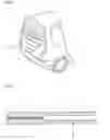
DESCRIPTION OF DRAWINGSFIG. 1 is a partial perspective view showing a state where a tail gate is mounted to a vehicle.
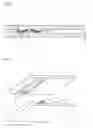
FIG. 2 is a sectional view of a related art plastic panel.
FIG. 3 is a sectional view showing a bonded structure of a plastic panel according to an embodiment of the present invention.
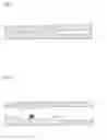
FIG. 4 is a perspective view of the plastic panel according to the embodiment of the present invention in which stoppers are employed.
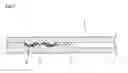
FIGS. 5 to 7 are sectional views illustrating a process of assembling the plastic panel according to the embodiment of the present invention.
EXPLANATION OF REFERENCE NUMERALS FOR DESIGNATING MAIN COMPONENTS IN THE DRAWINGS
| 1: Tail gate | 2: Inner panel | |
| 3: Outer panel | 4: Adhesive | |
| 5: Stopper | 6: Additional space | |
| 7: Bonding Groove | 8: Protrusion | |
[Best Mode]
Hereinafter, the present invention will be described in detail with reference to the accompanying drawings.
FIG. 1 is a partial perspective view showing a state where a tail gate is mounted to a vehicle, FIG. 2 is a sectional view of a related art plastic panel, FIG. 3 is a sectional view showing a bonded structure of a plastic panel according to an embodiment of the present invention, FIG. 4 is a perspective view showing a state where stoppers are of the plastic panel according to the embodiment of the present invention in which stoppers are employed, and FIGS. 5 to 7 are sectional views illustrating a process of assembling the plastic panel according to the embodiment of the present invention.
Inner and outer panels 2 and 3 constituting the plastic panel of the present invention can be manufactured from sheet molding compounds (SMC), glass mat thermoplastics (GMT), polyethylene terephthalate (PET), PA, PC and the like as a raw material by means of the general compression molding method or injection molding method. The inner and outer panels 2 may be the same as or different from each other in view of thickness.
In the plastic panel of the present invention, at least one bonding groove 7 in which an adhesive is applied is formed on any one of the inner and outer panels 2 and 3.
The other of the inner and outer panels 2 and 3, in which the bonding groove is not formed, is formed with a bonding surface at a position corresponding to the bonding groove 7 such that the bonding surface can be bonded to the bonding groove using the adhesive 4 applied to the bonding groove.
The bonding surface may be formed in the shape of a plane or protrusion. Preferably, the bonding surface is shaped as a protrusion. In a case where the bonding surface is shaped as a protrusion, it is more preferred that the bonding surface be shaped as a protrusion 8 corresponding to a shape of the bonding groove. Even in such a case, it is preferred that a space with a certain interval (gap) be formed between a bottom surface of the protrusion and a floor surface of the bonding groove such that an adhesive can be injected (applied) at a proper thickness in the gap of the space.
Since the plastic panel obtained by mechanically coupling the inner and outer panels 2 and 3 with each other using a bolt and nut cannot be tightly sealed, the inner and outer panels are generally assembled into the plastic panel by means of a chemical bonding method using an adhesive. The plastic panel of the present invention is manufactured in such a manner that the adhesive 4 is applied to the bonding groove 7 formed along an edge of the inner or outer panel 2 or 3 and the two panels are then coupled and bonded to each other.
The inner and outer panels 2 and 3 of the plastic panel according to the present invention have one or two or more bonding grooves having various sectional shapes such that a bonding strength higher than a certain level can be maintained after the inner and outer panels have been bonded to each other. Once the number and sectional shape of the bonding grooves 7 to be formed is determined, a width and depth of the bonding groove can be determined and formed such that the adhesive can be applied to the bonding groove to a suitable bonding area and thickness enough to keep bonding strength to the certain level or more. The bonding area and thickness by which the bonding strength can be maintained after two panels have been bonded may vary according to the kinds of adhesive. However, once the adhesive is selected, at least one bonding groove 7 with a width and depth suitable for the selected adhesive can be formed. For example, if a bonding area and thickness of the bonding groove suitable for the kind of selected adhesive is determined, at least one bonding groove 7 and the corresponding protrusion, if necessary, enough to ensure the suitable width and thickness are manufactured. Then, a volume of an adhesive to be applied is calculated and the adhesive as much as the calculated volume is applied to the bonding groove. Therefore, the two panels can be coupled and bonded to each other. At this time, the amount of the adhesive applied is set slightly smaller than the volume of the bonding groove 7 formed between the inner and outer panels, and thus, it is possible to prevent the applied adhesive from leaking out between the bonded panels.
In the present invention, an additional space or spaces 6 are further formed at one or both sides of the bonding groove by extending the bonding groove 7 toward the one or both sides. Therefore, even though the adhesive is injected in the bonding groove more than the volume of the bonding groove, it is possible to prevent the applied adhesive from leaking out between the bonded panels. In a case where the additional spaces are formed at both sides of the bonding groove, their widths can be different from each other. Further, the additional space 6 can be formed to have the same depth (See FIGS. 3 to 7). However, the depth of the additional space can be gradually decreased away form the bonding groove such that the bonding area per an amount of adhesive applied can be increased.
On the other hand, a stopper can be configured (formed) on the bonding groove or the bonding surface corresponding to the bonding groove to prevent an incomplete bonding state from occurring at the bonded region or prevent the thickness of the applied adhesive from being decreased when the inner and outer panels are pressed and then bonded to each other.
In the present invention, it is most desirable that a thickness (height) of the stopper be equal to the gap between the floor surface of the bonding groove and the bonding surface. However, the height may be slightly less than the gap. Further, a width enough to withstand a bonding pressure applied when the inner and outer panels are bonded and coupled to each other is sufficient for the stopper. Accordingly, it is preferred that the width of the stopper be formed as narrow as possible.
The stoppers 5 can be formed on the bonding groove or bonding surface at regular intervals (See FIG. 4). Alternatively, the stopper 5 can be formed to continuously extend along the bonding groove or bonding surface (not shown).
Further, the stopper 5 can be separately manufactured and then placed on the bonding surface or bottom surface of the bonding groove 7. Alternatively, the stopper can be formed integrally with the panel.
Since the stopper 5 is formed, the bonding groove and bonding surface cannot be further pressed. Thus, the two panels can be bonded to each other with a predetermined pressure. Due to the aforementioned structure of the present invention, therefore, an amount of adhesive used more than necessary can be minimized, and the conventional problem in that the fluid adhesive leaks out between the inner and outer panels and contaminates the exterior of the plastic panel can also be solved. Furthermore, a bonding force can be maximized.
INDUSTRIAL APPLICABILITYThe plastic panel of the present invention can be usefully applied to a vehicle door, in particular, a panel for a tail gate.
The present invention has the following advantages. That is, since the bonding groove is bonded to the bonding surface of the inner or outer panel, it is possible to prevent the applied adhesive from leaking to the outside. Further, since the bonding groove formed on the inner or outer panel serves as a guide when the adhesive is applied, the adhesive can be applied at a uniform thickness to correct positions even though it is manually applied. Furthermore, since a stopper and additional space are provided on the bonding groove or bonding surface, even an adhesive with certain fluidity cannot leak out between the inner and outer panels. Therefore, the post-processing work for enhancing the external appearance is not required, the manufacturing time and costs can be reduced, and the bonding force can be increased due to the increased bonding area.
Claims
1. A plastic panel, comprising:
an inner panel formed with any one of a bonding groove to be coated with an adhesive and a bonding surface corresponding to the bonding groove; and
an outer panel formed with the other of the bonding groove and bonding surface.
2. The plastic panel as claimed in claim 1, wherein the bonding groove is formed on the inner panel.
3. The plastic panel as claimed in claim 1, wherein an additional space extends from the bonding groove.
4. The plastic panel as claimed in claim 1, wherein the bonding surface is shaped as a protrusion corresponding to a shape of the bonding groove.
5. The plastic panel as claimed in claims 1, wherein the bonding groove or bonding surface is formed with a stopper.
6. The plastic panel as claimed in claim 5, wherein the stopper has a height (thickness) which is equal to or smaller than a gap between the bonding surface and a floor surface of the bonding groove.
7. The plastic panel as claimed in claim 6, wherein the stopper is formed integrally with the inner or outer panel.
8. The plastic panel as claimed in claim 7, wherein the plastic panel is used for a vehicle door.
Images & Drawings included:

Sources:
- United States Patent and Trademark Office - verify current appl. status at the USPTO↗
Similar patent applications:
- » 20240352745
DECORATIVE PLASTIC PANEL AND METHOD OF FABRICATING DECORATIVE PLASTIC PANELS - » 20070090083
Squeezable multi-panel plastic container with smooth panels - » 20100301003
Multi-panel plastic container with asymmetric vacuum panels - » 20070199253
Reinforced blow-molded plastic panels and structures - » 20070187391
Electrical connection to printed circuits on plastic panels - » 20050120641
Low profile plastic panel enclosure - » 20070075032
Multi-panel plastic container - » 20060157462
Heat enhancement in critical viewing area of transparent plastic panel - » 20060204746
Plastic panels with uniform weathering characteristics - » 20060012071
Method of manufacturing a metal-reinforced plastic panel
Recent applications in this class:
- » 20250135729 2025-05-01
Method and Apparatus for Connecting and Reinforcing Pre-Manufactured Parts - » 20250065573 2025-02-27
METHOD FOR JOINING SILICONE RUBBER USING PLASMA TREATMENT - » 20230286221 2023-09-14
Electric heating pad - » 20230241843 2023-08-03
ENHANCED FRACTURE TOUGHNESS OF BONDED JOINTS USING TAILORED SACRIFICIAL CRACKS - » 20230050811 2023-02-16
METHOD OF MANUFACTURING A WIND TURBINE BLADE AND SHEAR WEB ASSEMBLY FOR A WIND TURBINE BLADE - » 20230034977 2023-02-02
Electric heating pad - » 20230016964 2023-01-19
Joint structure and method for manufacturing joint structure - » 20220410499 2022-12-29
SYSTEMS AND METHODS FOR MATING COMPONENTS - » 20220363015 2022-11-17
EMBEDDED POLYMERIC INSERT FOR INCREASED TOUGHNESS OF ADHESIVE BONDED JOINT - » 20220332055 2022-10-20
SUPPORT STRUCTURE FOR A PERSONAL CARE PRODUCT