Device for impact sensing having at least two pressure sensors
US20060155504A1
2006-07-13
10/524,217
2003-02-24
✅ Patent granted
US 7,664,609 B2
2010-02-16
WO; PCT/DE03/00562; 20030224
WO; WO2004/018263; 20040304
Eliseo Ramos Feliciano | Janet L Suglo
2023-02-24
Abstract:
A device for impact sensing having at least two pressure sensors is described, where pressure values are communicated from the pressure sensors to a processor, and the processor performs impact sensing on the basis of the pressure value. The processor communicates the pressure values to additional vehicle systems, which use them to fulfill their own functions, or at least to carry out a plausibility check of their own pressure values.
Assignee:
- Robert Bosch GMBH 19,123 🇩🇪 Stuttgart, Germany
Interested in similar patents?
Get notified when new applications in this technology area are published.
Classification:
B60R21/16 IPC
Arrangements or fittings on vehicles for protecting or preventing injuries to occupants or pedestrians in case of accidents or other traffic risks; Occupant safety arrangements or fittings, e.g. crash pads Inflatable occupant restraints or confinements designed to inflate upon impact or impending impact, e.g. air bags
B60R21/013 » CPC main
Arrangements or fittings on vehicles for protecting or preventing injuries to occupants or pedestrians in case of accidents or other traffic risks; Electrical circuits for triggering safety arrangements, in case of vehicle accidents or impending vehicle accidents including means for detecting collisions, impending collisions or roll-over
B60R21/0136 » CPC further
Arrangements or fittings on vehicles for protecting or preventing injuries to occupants or pedestrians in case of accidents or other traffic risks; Electrical circuits for triggering safety arrangements, in case of vehicle accidents or impending vehicle accidents including means for detecting collisions, impending collisions or roll-over responsive to actual contact with an obstacle, e.g. to vehicle deformation, bumper displacement or bumper velocity relative to the vehicle
B60R2021/01061 » CPC further
Arrangements or fittings on vehicles for protecting or preventing injuries to occupants or pedestrians in case of accidents or other traffic risks; Electrical circuits for triggering safety arrangements, in case of vehicle accidents or impending vehicle accidents; Communication circuits for data transmission; Architecture; Bus between the airbag system and other vehicle electronic systems
B60R2021/0119 » CPC further
Arrangements or fittings on vehicles for protecting or preventing injuries to occupants or pedestrians in case of accidents or other traffic risks; Electrical circuits for triggering safety arrangements, in case of vehicle accidents or impending vehicle accidents; Prevention of malfunction; Fault detection or diagnostic circuits Plausibility check
B60R2021/01345 » CPC further
Arrangements or fittings on vehicles for protecting or preventing injuries to occupants or pedestrians in case of accidents or other traffic risks; Electrical circuits for triggering safety arrangements, in case of vehicle accidents or impending vehicle accidents including means for detecting collisions, impending collisions or roll-over responsive to imminent contact with an obstacle, e.g. using radar systems using mechanical sensing means
G06F15/00 IPC
Digital computers in general ; Data processing equipment in general
G01L27/00 IPC
Testing or calibrating of apparatus for measuring fluid pressure
G01L7/00 IPC
Measuring the steady or quasi-steady pressure of a fluid or a fluent solid material by mechanical or fluid pressure-sensitive elements
G01L7/00 IPC
Measuring fluid pressure
G01L15/00 IPC
Devices or apparatus for measuring two or more fluid pressure values simultaneously
Description
FIELD OF THE INVENTIONThe present invention relates to a device for impact sensing having at least two pressure sensors.
BACKGROUND INFORMATIONGerman Patent Application No. DE 102 101 31.0 (not a prior publication) describes communicating absolute pressure values as well as differential pressure values.
SUMMARYAn example device according to the present invention for impact sensing having at least two pressure sensors may have the advantage over the related art that the pressure values of the pressure sensors of the example device according to the present invention may now also be made available to other vehicle systems. To that end, the example device according to the present invention is connected to those other vehicle systems, for example, through a bus, in order to communicate the pressure values to those vehicle systems also. The other vehicle systems may use these pressure values to check the plausibility of their own sensor values and/or as a substitute for a nonexistent sensor. This enables inexpensive multiple use of the pressure signals of the pressure sensors for impact detection. The additional hardware complexity is small, since in most cases an interface or a bus system to other vehicle systems is already present. The result is that pressure sensors may be eliminated for the other vehicle systems. This may also simplify the design of the electronic systems in a vehicle.
It is particularly advantageous if the at least one additional vehicle system is an injection system, a climate-control system and/or a barometer function. An altitude-measuring system based on pressure may also profit from the example device according to the present invention.
The pressure value may be communicated advantageously to the other vehicle systems as an absolute pressure value or as a differential pressure value.
BRIEF DESCRIPTION OF THE DRAWINGSExemplary embodiments of the present invention are illustrated in the figures and are explained in greater detail below.
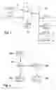
FIG. 1 shows a block diagram of an example device according to the present invention.
FIG. 2 shows a flow chart of the sequence of operations on the example device according to the present invention.
DETAILED DESCRIPTION OF EXAMPLE EMBODIMENTSPressure sensors are known from industry and from automotive applications. Depending on the design, the pressure sensors communicate absolute or differential pressure values to an analyzer unit. In the automobile, the sensors are usually utilized for controlling the engine and for sensing side crashes and triggering an airbag.
According to the example embodiment of the present invention, the pressure values which are constantly being recorded and communicated to the control unit by the sensors present for impact sensing are also made available to other vehicle systems. This may make it possible under some circumstances to eliminate pressure sensors or to check pressure sensors for plausibility which are present in other vehicle systems.
FIG. 1 shows a block diagram of the example device according to the present invention. Two pressure sensors 1 and 2, which are used for impact sensing, are connected via corresponding lines 3 and 4 to a processor 5. Through a third data input, processor 5 receives signals from an acceleration sensor 10, which is used to check the plausibility of the pressure sensor signals from sensors 1 and 2. Through a data input/output, processor 5 is connected to a bus 11, to which additional vehicle systems 6 through 9 are connected. Vehicle system 6 is an injection system, vehicle system 7 is a climate-control system, vehicle system 8 is a barometer function having an on-board computer, and vehicle system 9 is an altimeter.
Pressure sensors 1 and 2 are designed as micromechanical pressure sensors, which are used here for sensing side impacts and are thus located in a side part of the vehicle. The side part is largely closed, so that when a side impact occurs, pressure sensors 1 and 2 detect an adiabatic pressure increase through the deformation of the side part. That makes it possible for pressure sensors 1 and 2 to sense a side impact very quickly. Pressure sensors 1 and 2 therefore function as indirect deformation sensors.
Alternatively or additionally, it is also possible to utilize pressure sensors in the bumper or the rear, in order to also detect an impact there through an adiabatic pressure increase. More than two sensors may be used for side impact sensing. However, the use of at least two sensors makes it possible to ensure a reciprocal check of the performance of pressure sensors 1 and 2 through the evaluation of the signals that are communicated to the processor via lines 3 and 4. Because pressure sensors 1 and 2 are located in the side parts, which are opposite each other, they are positioned in the vehicle away from a control unit. Sensors 1 and 2 have measuring amplifiers, an analog-digital converter and a transmitting element, in order to communicate the measured pressure data to processor 5. Here, unidirectional communication is provided from sensors 1 and 2 to processor 5 in a control unit. Lines 3 and 4 are also used to supply power to pressure sensors 1 and 2, the pressure sensors communicating their data to processor 5 over this direct current through amplitude modulation. Processor 5 has one receiving module each for lines 3 and 4, in order to receive the transmitted data. Alternatively, it is possible for the connection between pressure sensors 1 and 2 and processor or control unit 3 to be bidirectional, so that control unit 5 is also able to communicate queries to pressure sensors 1 and 2. It is further possible for pressure sensors 1 and 2 to communicate not only their measurement data to control unit 5 or the processor, but also data that have already been analyzed, for example differential pressure data or normalized data. In addition, it is possible for the connection between pressure sensors 1 and 2 and control unit 5 to be implemented via a bus, i.e., a sensor bus. This would enable control unit 5 to use only a single bus controller, and also only a single line to which sensors 1 and 2 are connected. Acceleration sensor 10 is provided here as a plausibility sensor for an impact. This means that only if acceleration sensor 10 also indicates an impact does processor 5 decide that an impact has occurred, and activates restraining means such as airbags and belt tensioners, which are not shown here. However, if no impact has occurred, control unit 5 communicates the pressure data of the two sensors 1 and 2 to the other control units 6 through 9. These use the pressure data to check the plausibility of their own sensors or to carry out their function with this pressure data. In particular, comfort functions such climate-control system 7, barometer function 8 and altimeter 9 may dispense with pressure sensors of their own and use the values from pressure sensors 1 and 2.
From the point of view of functions alone, it is possible to dispense with the additional sensor 10 used here for plausibility checking, if it is possible to tolerate impairment of the functions of the other vehicle systems 6-9, designed mostly for comfort, in the event of a crash, or if this impairment is slight.
It is also possible for control unit 5 to be connected to vehicle systems 6, 7, 8 and 9 via two wire connections each. A wireless or optical connection is also feasible here.
FIG. 2 shows a flow chart to explain the sequence of operations on processor 5. In process step 100, processor 5 receives the pressure data from sensors 1 and 2. In process step 101, processor 5 uses the signal from acceleration sensor 10 to check whether an impact has occurred. If both the pressure data and the acceleration data indicate a side impact, then the system jumps to process step 102, and restraining means corresponding to the severity of the impact are triggered. But if no impact was detected in process step 101, which is the normal case, then the system jumps to process step 103, and the pressure data from sensors 1 and 2 is communicated to vehicle components 6 through 9. In process step 104, vehicle systems 6 through 9 then carry out their functions with the pressure data. Thus, it is advantageously possible for vehicle systems 6 through 9 to perform plausibility checks of their own measured values, or to use these pressure values directly for their own functions.
Claims
1-5. (canceled)
6. A device for impact sensing, comprising:
a processor; and
at least two pressure sensors connectable to the processor to communicate at least one pressure value each to the processor, the processor being configured to perform an impact sensing based on the at least one pressure value;
wherein the processor is connectable to at least one additional vehicle system to transmit the at least one pressure value to the at least one additional vehicle system.
7. The device as recited in claim 6, wherein the at least one additional vehicle system is at least one of an injection system, a climate-control system, a barometer function, and an altitude measuring function.
8. The device as recited in claim 6, wherein the at least one additional vehicle system is configured to use the at least one pressure value for plausibility checking.
9. The device as recited in claim 6, wherein the at least one additional vehicle system is configured to control its function as a function of the at least one pressure value.
10. The device as recited in claim 6, wherein the at least one pressure value is an absolute pressure value or a differential pressure value.
Images & Drawings included:

Sources:
- United States Patent and Trademark Office - verify current appl. status at the USPTO↗
Recent applications in this class:
- » 20250214524 2025-07-03
LOW-POWER ANALOG VEHICLE MONITORING SYSTEM - » 20250178554 2025-06-05
System and Method for Automated Vehicle Accident Detection and Safety-Protocol Activation - » 20250153670 2025-05-15
METHOD AND APPARATUS FOR CONTROLLING ROLLOVER PREVENTION OF TANK TRUCK, CLOUD, TANK TRUCK, AND SYSTEM FOR CONTROLLING ROLLOVER PREVENTION OF TANK TRUCK - » 20250136030 2025-05-01
CRASH DETECTION CIRCUIT FOR BATTERY MANAGEMENT UNIT - » 20240351543 2024-10-24
DEVICE HAVING ELECTROMECHANICAL TRANSDUCERS FOR DETECTING APPROACH AND/OR CONTACT IN A MOTOR VEHICLE - » 20240343217 2024-10-17
ENERGY-EFFICIENT COLLISION DETECTION AND MOTION PLANNING - » 20240190373 2024-06-13
Active Adaptive Interior Surface Mechanism - » 20240174194 2024-05-30
CONTROL DEVICE - » 20240092299 2024-03-21
Event-based connected vehicle control and response systems - » 20240075895 2024-03-07
CRASH DETECTION ON MOBILE DEVICE
Recent applications for this Assignee:
- » 20250154889 2025-05-15
PRESSURE CONTROL IN AN EXHAUST AFTERTREATMENT SYSTEM - » 20250154580 2025-05-15
ENZYME TRANSLOCATORS IN NANOGAP WITH 3' -ESTERS - » 20250147582 2025-05-08
METHOD FOR DETERMINING AN EYE DISTANCE IN A PAIR OF DATA GLASSES, AND DATA GLASSES - » 20250146568 2025-05-08
DRIVE ASSEMBLY AND VEHICLE HAVING SUCH A DRIVE ASSEMBLY - » 20250146495 2025-05-08
Flexible Pump Assembly for Use in a Fan Drive - » 20250140882 2025-05-01
FUEL CELL SYSTEM HAVING ENERGY RECUPERATION - » 20250137810 2025-05-01
METHOD FOR MATCHING A DIGITAL ROAD MAP - » 20250137033 2025-05-01
DNA UNFOLDING USING A FREE-END TAG FLOW MODIFIER - » 20250119751 2025-04-10
A BLUETOOTH COMMUNICATION METHOD AND SYSTEM - » 20250118116 2025-04-10
Diagnostic Protocol Search With Improved Efficiency