Locking device for a telescopic stem of a trolley
US20060157945A1
2006-07-20
10/563,174
2004-06-25
✅ Patent granted
US 7,370,877 B2
2008-05-13
WO; PCT/NO2004/000189; 20040625
WO; WO2005/002945; 20050113
Hau Phan
2024-09-06
Abstract:
Locking device for a telescopic stem for a trolley wherein the stem comprises an inner stem and an outer stem, which may glide into each other, characterised in that a friction element is arranged in the outer stem and that the inner stem is equipped with the blocking element grasping into the friction element and locking the movement of the inner stem in relation to the outer stem, in that the blocking element presses against the friction element of housing with a conical groove linked to a rod stretching from the housing to the upper end of the inner stem and connected to a handle which influences the position of the housing.
Assignee:
- Stokke AS 7 🇳🇴 Skodje, Norway
Interested in similar patents?
Get notified when new applications in this technology area are published.
Classification:
B62B9/20 » CPC main
Accessories or details specially adapted for children's carriages or perambulators Handle bars; Handles
F16B7/1463 » CPC further
Connections of rods or tubes, e.g. of non-circular section, mutually, including resilient connections; Telescoping systems locking in intermediate positions with the expansion of an element inside the outer telescoping member due to the axial movement towards a wedge or a conical member
B62B5/065 » CPC further
Accessories or details specially adapted for hand carts; Hand moving equipment, e.g. handle bars adaptable for different users, e.g. by means of pivoting elements by means of telescopic elements
Y10T16/451 » CPC further
Miscellaneous hardware [e.g., bushing, carpet fastener, caster, door closer, panel hanger, attachable or adjunct handle, hinge, window sash balance, etc.]; Handle, handle component, or handle adjunct Length adjustable pull handle for luggage or luggage cart [e.g., wheeled suitcase handle, etc.]
B62B3/00 IPC
Hand carts having more than one axis carrying transport wheels; Steering devices therefor; Equipment therefor
B62B11/00 IPC
Hand-propelled vehicles not otherwise provided for
B62B1/00 IPC
Hand carts having only one axis carrying one or more transport wheels; Equipment therefor
B62B1/00 IPC
Hand carts
Description
The present invention relates to a locking device for a telescopic stem with handle, for a trolley, and especially a children's trolley such as described in Norwegian patent 315230. The trolley comprises a central stem wherein a seat or another module may be height adjusted along the stem, and the height of the handle may be regulated in that the stem may be lengthened telescopically.
BACKGROUND OF THE INVENTIONIt is proposed in the above mentioned patent that the central stem of the trolley can be lengthened in that the stem consists of two parts, wherein the upper part may, for example, be moved within the lower part. In order to lock the stem parts in relation to each other, a locking sleeve may for example be used at the transition between the parts.
The disadvantage of this solution is that the area around the transition is not easily accessible, since modules such as a children's seat which may be height adjusted all the way up to just under the transition, hinder access to the lock.
A telescopic handle is known from U.S. Pat. No. 4,302,029 on a golf trolley, wherein the inner and outer stems glide into each other and are locked by a locking pin, which penetrates both stems in the upper part of the outer stem.
There therefore exits a need for a locking device which may be remotely controlled from a more accessible area on the trolley.
OBJECT OF THE INVENTIONThe object of the invention is to provide a solution for the remote control of a telescopic stem on a trolley, especially a children's trolley.
DETAILED DESCRIPTION OF THE INVENTIONThe above objects are achieved by a remote controlled locking device wherein the stem comprises an inner stem (1) connected to a handle (1a) and an outer stem (2), wherein the inner stem can glide inside the outer stem, wherein a blocking element is present which locks movement of the inner stem (1) in relation to the outer stem (2), characterised in that a friction element (3) is placed in the outer stem (2) and that the inner stem (1) is equipped with the blocking element (4) grasping into the friction element (3) and locking the movement of the inner stem (1) in relation to the outer stem (2), in that the blocking element (4) is pressed against the friction element (3) of housing (5) with a conical groove (6) linked to a rod (7) stretching from the housing (5) to the upper end of the inner stem (1) and connected to a handle (8) which actuate the position of the house (5).
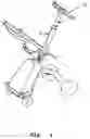
DESCRIPTION OF THE FIGURESFIG. 1 depicts a perspective view of a trolley as described over.
FIG. 2 is a section of the stem of the trolley in FIG. 1.
FIG. 3 depicts an enlargement of the marked area in FIG. 2.
PREFERRED EMBODIMENTThe present invention is achieved by an inner stem 1 and an outer stem 2 wherein the inner stem 1 may glide into the outer stem 2 as shown in FIG. 1. The stems preferably have about the same cross sectional shape in order to hinder slack between the stems. A sleeve 20 prevents dirt and particles from entering between the stems as shown in FIG. 2.
The outer stem 2 is equipped with a friction element 3, as shown in greater detail in FIG. 3. The friction element 3 stretches over a large portion of the length of the outer stem 2. The inner stem 1 is equipped with a corresponding blocking element 4 which may lock into the friction element 3 and lock the movement of the inner stem 1 in relation to the outer stem 2. In this embodiment the friction element 3 is arranged on an inner area of the outer stem 2 and the blocking element 4 is arranged on the lower end of the inner stem 1, opposite the friction element 3.
The blocking element 4 presses against the friction element 3, achieved by that spring-loaded housing with a cocked or conical area or track 6 contained within, is pressed against the blocking element 4. The housing 5 is linked to a rod 7 which extends from the lower end of the inner stem 1 to the upper end of the inner stem 1, where the rod is linked to a handle 8, which tilts around an axis and is used to adjust the positioning of the housing.
In FIGS. 2 and 3, the house 5 is in the lower position such that the inner stem 1 may move up or down in the outer stem 2, by releasing the blocking element 4 in relation to the friction element 3. The handle 8 is then in an elevated position, pressing the rod downwards in the lower position against the spring loading, provided by a spring 9, straining the housing 5 up from the end of the inner stem 1. When the handle 8 is pushed downward, the rod 7 is thereby pulled up and the house 5 presses the blocking element 4 into the friction element 3 and locking the movement of the inner stem 1 in relation to the outer stem 2.
As shown in FIG. 2, the end of the inner stem may move freely between an upper position limited by a sleeve 20, on the outer part of the upper end of the stem 2, and a lower position limited by an inner clamp 21 on the inside of the outer stem 2.
Claims
1. Locking device for a telescopic stem for a trolley, wherein the stem comprises an inner stem connected to a handle, which may glide within an outer stem, a handle at the upper end of the inner stem for controlling the locking of the inner stem in relation to the outer stem, the handle connected to a rod running through the inner stem, characterised in that a toothed friction element is arranged in the outer stem and that the inner stem is equipped with a toothed blocking element locking into the friction element and preventing movement of the inner stem in relation to the outer stem when the blocking element is pressed into the toothed friction element by a conical groove of a housing connected to the rod influencing the position of the housing.
2. Locking device according to claim 1, characterised in that the friction element is arranged on an inner area of the outer stem.
3. Locking device according to any one of claims 1-2, characterised in that the a blocking element is arranged on the lower side of the stem, opposite the friction element.
4. Locking device according to any one of claims 1-3, characterised in that the housing and/or the blocking element is spring-loaded by a spring, automatically affecting locking by the friction element.
Images & Drawings included:


Sources:
- United States Patent and Trademark Office - verify current appl. status at the USPTO↗
Recent applications in this class:
- » 20250282408 2025-09-11
BABY STROLLER HANDLE DEVICE - » 20220355846 2022-11-10
Cart handle and baby cart - » 20220274638 2022-09-01
PRAM - » 20220073121 2022-03-10
Attachment for push apparatus - » 20210261184 2021-08-26
Handle extension for stroller - » 20210229729 2021-07-29
STROLLER AND OPERATION METHOD THEREOF - » 20210188340 2021-06-24
Attachment for a pushable device - » 20210053606 2021-02-25
Handle folding mechanism, three-fold handle employing the folding mechanism, and stroller having the same - » 20200031381 2020-01-30
Detachable brace for collapsible stroller - » 20180134307 2018-05-17
STEERABLE JOGGING STROLLER
Recent applications for this Assignee:
- » 20150217793 2015-08-06
Foldable stroller - » 20130214571 2013-08-22
Baby cradle and mounting device - » 20110095593 2011-04-28
DEVICE FOR A CHILD'S CHAIR - » 20080265650 2008-10-30
Fastening bracket - » 20060152059 2006-07-13
Device for height adjustment of a child seat and telescopically adjustable foot support - » 20060138837 2006-06-29
Mobile joint suitable for a sitting device