Enhanced mechanism for radio frequency identification reader
US20060158334A1
2006-07-20
11/213,721
2005-08-30
✅ Patent granted
US 7,388,500 B2
2008-06-17
-
-
Hung Nguyen
2026-04-19
Abstract:
The invention relates to an enhanced mechanism for RFID reader which includes: an antenna for receiving a RFID signal transmitted from an object under test and outputting the RFID signal to the RFID reader; a metal plate disposed on an entrance of a building. The metal plate and the object under test are respectively placed on opposite sides of the antenna. The angle between the first metal plate and the second metal plate is from 30 to 180 degrees; therefore the metal plate, the antenna, and the RFID reader provide an enhanced mechanism of a RFID reader.
Assignee:
- TATUNG COMPANY 149 🇹🇼 Taipei, Taiwan
- TATUNG UNIVERSITY 56 🇹🇼 Taipei, Taiwan
- Tatung Co., Ltd. 116 🇹🇼 Taipei City, Taiwan
Interested in similar patents?
Get notified when new applications in this technology area are published.
Classification:
H01Q1/2216 » CPC main
Details of, or arrangements associated with, antennas; Supports; Mounting means by structural association with other equipment or articles associated with components used in interrogation type services, i.e. in systems for information exchange between an interrogator/reader and a tag/transponder, e.g. in Radio Frequency Identification [RFID] systems used in interrogator/reader equipment
G06K7/0008 » CPC further
Methods or arrangements for sensing record carriers, e.g. for reading patterns General problems related to the reading of electronic memory record carriers, independent of its reading method, e.g. power transfer
G06K7/10316 » CPC further
Methods or arrangements for sensing record carriers, e.g. for reading patterns by electromagnetic radiation, e.g. optical sensing; by corpuscular radiation sensing by radiation using wavelengths larger than 0.1 mm, e.g. radio-waves or microwaves using at least one antenna particularly designed for interrogating the wireless record carriers
H01Q1/52 IPC
Details of, or arrangements associated with, antennas Means for reducing coupling between antennas; Means for reducing coupling between an antenna and another structure
G08B13/14 IPC
Burglar, theft or intruder alarms; Mechanical actuation by lifting or attempted removal of hand-portable articles
Description
BACKGROUND OF INVENTION1. Field of the Invention
The present invention relates to Radio Frequency Identification (RFID) reader and, more particularly, to an enhanced mechanism for RFID reader.
2. Description of Related Art
RFID is suitable for use of tag and reader, which applies the technique of wireless radio waves to identify objects automatically. The frequency band of RFID includes low frequency (125 k-135 kHz), high frequency (13.56 MHz), ultra high frequency (UHF 860-930 MHz), microwave (2.45 GHz), etc. Characteristics of different frequencies have different applications. For the RFID of electromagnetic induction type, the antenna of the reader continuously emits electromagnetic pulses, and the antenna coil of the RFID tag uses magnetic field to produce electric currents. The drive chip induces a coupling effect to start a certification process, which transfers the stored information to the reader within an operative distance. Then, the reader will transform and transfer the received information to an edge server to be encoded and processed. Therefore, RFID technique can be applied in a tracing device for merchandise management. For example, if the merchandises pass through the effective area of a special scanning device, the RFID reader will be able to locate its exact position.
As shown in FIG. 1, when merchandises pass through the entrance of a building, antenna 15 can receive the RFID signal reflected by the RFID tag 14 on the subject, and then it outputs the received RFID signal to a RFID reader 16. However, the RFID signal reflected by the RFID tag 14 on the object is passive, so the signal is weak. If the transmission distance is too long, or the RFID tag is attached to a dead space, both cases will result in the situation of ineffective RFID signal identification. Therefore, it is desired to provide an effective RFID signal receiver to mitigate and/or obviate the aforementioned problems.
SUMMARY OF THE INVENTIONThe present invention has been accomplished under the circumstances in view. The present invention relates to an enhanced mechanism for RFID reader, which includes an antenna and a metal plate device. The antenna can receive RFID signal transmitted from an object under test and output the RFID signal to the RFID reader. The metal plate device is disposed on an entrance of a building. The metal plate and the object under test are respectively placed on the opposite sides of the antenna. Such a metal plate device is formed by two metal plates, forming an angle between 30 and 180 degrees. The operating frequency of RFID signal can be set between ultra high frequency and microwave frequency. The combination of the antenna and metal plates forms a better antenna transmitting system. Being linked with RFID tag, RFID signal reader can improve its receiving capability and avoid missing weaker signal, and thus an effective RFID signal receiver can be improved.
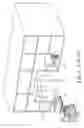
BRIEF DESCRIPTION OF THE DRAWINGSFIG. 1 is a schematic view of a RFID reader.
FIG. 2 is a schematic view of an enhanced mechanism for a RFID reader in accordance with the first preferred embodiment of the present invention.
FIG. 3 is a schematic view of an enhanced mechanism for a RFID reader in accordance with the second preferred embodiment of the present invention.
FIG. 4 is a schematic view of an enhanced mechanism for a RFID reader in accordance with the third preferred embodiment of the present invention.
FIG. 5 is a schematic view of an enhanced mechanism for a RFID reader in accordance with the fourth preferred embodiment of the present invention.
DETAILED DESCRIPTION OF THE PREFERRED EMBODIMENTThe present invention discloses an enhanced mechanism for radio frequency identification reader. Referring to FIG. 2, the first metal plate 21 and the second metal plate 22 form an angle of 180 degrees, placing on an entrance of a building 12. When a truck 13 passes through the entrance of the building 12, the RFID tag 14 on the truck 13 will send out the RFID signal. The combination of the antenna 15 and metal plate 21 and 22 provides an antenna transmitting system with a high gain. When the transmitting system is linked with the RFID tag 14, the RFID signal will reach the reader 16, in which the information will be transformed and transferred to an edge server 17 to be decoded and processed. According to the Corner Reflector theory, the metal plate 21 and 22 can effectively strengthen the reception of antenna 15 of the RFID reader 16; as a result, it can effectively avoid the situation of low antenna gain for communication link.
Referring to FIG. 3, the angle between the first metal plate 21 and second metal plate 22 is 180 degrees, which is placed parallel to a partially reflective surface 31. Both the metal plates 21 and 22 and the partially reflective surface 31 are installed at the entrance of the building 12, with the antenna 15 in the middle. When a truck 13 passes through the entrance of the building 12, the RFID tag 13 on the truck 13 will send out the RFID signal. The combination of the partially reflective surface 31, the antenna 15, and metal plates 21 and 22 provides an antenna transmitting system with a better gain. When the transmitting system is linked with the RFID tag 14, the RFID signal will reach the reader 16. The reflective surface 31 and the metal plates 21 and 22 became a resonance cavity-like device; this mechanism can improve the radiated power gain. The antenna 15 will receive the gained signal and send the same to the reader 16, in which the information will be transformed and transferred to the edge server 17 to be decoded and processed.
Referring to FIG. 4, the angle of the first metal plate 21 and second metal plate 22 is between 30 to 180 degrees, placing at the entrance of the building 12. When the truck 13 passes through the entrance of the building 12, the RFID tag 14 on the truck 13 will send out the RFID signal. The combination of the antenna 15 and metal plates 21 and 22 provides an antenna transmitting system with a better gain. When the transmitting system is linked with the RFID tag 14, the RFID signal will reach the reader 16, in which the information will be transformed and transferred to an edge server 17 to be decoded and processed. According to the Corner Reflector theory, the metal plates 21 and 22 can effectively strengthen the reception of antenna 15 of the RFID reader 16; as a result, it can effectively avoid the situation of low antenna gain for communication link.
Referring to FIG. 5, the angle of the first metal plate 21 and second metal plate 22 is between 30 to 180 degrees, and a partially reflective surface 31 is placed under the metal plates 21 and 22. Both of the reflective surface 31 and the metal plates 21 and 22 are placed at the entrance of the building 12, and the antenna is placed in-between the metal plates 21 and 22 and the partially reflective surface 31. When a truck 13 passes through the entrance of a building 12, the RFID tag 14 on the truck 13 will send out the RFID signal. The combination of the partially reflective surface 31, the antenna 15, and metal plates 21 and 22 provides an antenna transmitting system with a better gain. When the transmitting system is linked with the RFID tag 14, the RFID signal will reach the reader 16. The reflective surface 31 and the metal plates 21 and 22 became a resonance cavity-like device; this mechanism can improve the radiated power gain. The antenna 15 will receive the gained signal and send the same to the reader 16, in which the information will be transformed and transferred to an edge server 17 to be decoded and processed.
Furthermore, the antenna in the above embodiments can be a dipole antenna or a circular polarized antenna, and the standard RFID tag 14 can be its receiving media. As proven in the experiment, if the angle between the two metal plates is 180 degrees as shown in FIGS. 2 and 3, the use of circular polarized antenna has better effect in antenna gain. However, if the angle of the two metal plates is between 30 to 180 degrees as shown in FIGS. 4 and 5, the use of dipole antenna has better effect in antenna gain.
Although the present invention has been explained in relation to its preferred embodiment, it is to be understood that many other possible modifications and variations can be made without departing from the spirit and scope of the invention as hereinafter claimed.
Claims
What is claimed is:1. an enhanced mechanism for RFID reader, which comprises:
an antenna for receiving RFID signal transmitted from an object under test and outputting the RFID signal to the RFID reader; and
a metal plate device disposed on an entrance of a building, wherein the metal plate device and the object under test are respectively placed on the opposite sides of the antenna.
2. The enhanced mechanism for RFID reader as claimed in claim 1, wherein the metal plate device is formed by a first metal plate and a second metal plate.
3. The enhanced mechanism for RFID reader as claimed in claim 1, wherein the angle between the first metal plate and the second metal plate is from 30 to 180 degrees.
4. The enhanced mechanism for RFID reader as claimed in claim 1, further comprising a partially reflective surface disposed in-between the antenna and the object under test.
5. The enhanced mechanism for RFID reader as claimed in claim 1, wherein the antenna is a circular polarized antenna.
6. The enhanced mechanism for RFID reader as claimed in claim 1, wherein the antenna is a dipole antenna.
7. The enhanced mechanism for RFID reader as claimed in claim 1, wherein an operating frequency of RFID signal is an ultra high frequency.
8. The enhanced mechanism for RFID reader as claimed in claim 1, wherein an operating frequency of RFID signal is a microwave frequency.
Images & Drawings included:


Sources:
- United States Patent and Trademark Office - verify current appl. status at the USPTO↗
Recent applications in this class:
- » 20250266609 2025-08-21
MODULAR ANTENNA UNIT FOR CONSTRUCTING TAG READER PORTALS - » 20250219281 2025-07-03
ANTENNA DEVICE AND IC CARD HAVING THE SAME - » 20250030146 2025-01-23
RADIO FREQUENCY IDENTIFICATION (RFID) ANTENNA AND COMMUNICATION SYSTEM - » 20240396204 2024-11-28
RADIOFREQUENCY IDENTIFICATION EQUIPPED MEDICAL CABINET SYSTEMS AND METHODS OF ASSEMBLY AND USE THEREOF - » 20240372244 2024-11-07
ANTENNA FOR AN RFID READING DEVICE WITH POLARIZATION SWITCHING - » 20240291133 2024-08-29
Antenna Arrangement for RFID-Integrated Scanning Device - » 20240250407 2024-07-25
NFC READER WITH NFC ANTENNA AND WIRELESS CHARGING ANTENNA - » 20240113411 2024-04-04
RFID system - » 20240014541 2024-01-11
ELECTRONIC DEVICE - » 20230411824 2023-12-21
RADIO COMMUNICATION ANTENNA CONSISTING OF A PREVIOUSLY BENT RIGID METALLIC WIRE, SUPPORT STRUCTURE AND CORRESPONDING PAYMENT TERMINAL
Recent applications for this Assignee:
- » 20200283621 2020-09-10
Biodegradable plastic composition and manufacturing method thereof - » 20200283621 2020-09-10
Biodegradable plastic composition and manufacturing method thereof - » 20190065288 2019-02-28
Gateway, internet of things device control system and method thereof - » 20190065288 2019-02-28
Gateway, internet of things device control system and method thereof - » 20180265962 2018-09-20
Method of fabricating hydrophilic-hydrophobic transformable composite film - » 20180265962 2018-09-20
Method of fabricating hydrophilic-hydrophobic transformable composite film - » 20170063823 2017-03-02
Identity verification method, internet of thins gateway device, and verification gateway device using the same - » 20170063823 2017-03-02
Identity verification method, internet of thins gateway device, and verification gateway device using the same - » 20170063807 2017-03-02
Method for automatically establishing wireless connection, gateway device and client device for internet of things using the same - » 20170063807 2017-03-02
Method for automatically establishing wireless connection, gateway device and client device for internet of things using the same