Coupling element for inverted t beams
US20060165481A1
2006-07-27
10/531,909
2003-11-05
Abstract:
An improved coupling element for inverted T beams characterised by comprising at their ends an appendix (2) formed from two portions (8, 10) of different height, the outer portion (10) having the lesser height and being bent to V-shape with the free part (14) comprising a tooth (16), and in their central web (4) at least one aperture (18) having a height substantially corresponding to the height of the outer portion (10), for the insertion of said portion and its stable retention by the tooth and by the edge of the inner portion (8).
Interested in similar patents?
Get notified when new applications in this technology area are published.
Classification:
E04B9/122 » CPC main
Ceilings; Construction of ceilings, e.g. false ceilings; Ceiling construction with regard to insulation characterised by constructional features of the supporting construction, e.g. cross section or material of framework members; Connections between non-parallel members of the supporting construction one member passing through the other member, both members laying at least partly in the same plane
Y10T403/7001 » CPC further
Joints and connections; Interfitted members Crossed rods
E06B3/99 IPC
Window sashes, door leaves, or like elements for closing wall or like openings; Layout of fixed or moving closures, e.g. windows in wall or like openings ; Features of rigidly-mounted outer frames relating to the mounting of wing frames; Corner joints or edge joints for windows, doors, or the like frames or wings for continuous frame members crossing each other with out interruption
Description
The present invention relates to an improved coupling element for inverted T beams.
Structural elements for false ceilings are known consisting of beams of inverted T cross-section provided at their ends with hooks, which are either formed directly on the central web of the T beam or are in the form of inserts which are constructed separately and applied to each beam section during its construction.
Said beams are also provided in their web with cut-outs in which to engage the coupling element of a beam perpendicular to it, to form a lattice structure which is generally suspended from the ceiling, usually by steel cables or tie bars, to functionally support with its horizontal flanges those panels and staves or the like necessary to form the false ceiling.
A known type of beam comprises an element which is subjected to pressing to form an elastic strip in which, by cutting and plastic deformation, at least one tooth is defined having its abutment surface facing the beam, to form an insertion connection with the cut-out provided in the web of the beam.
A drawback of this coupling element is a certain laboriousness both in constructing the strip and in disengaging the strip from the cut-out in which it is engaged.
An object of the invention is to provide an improved coupling element which enables the appendix to be easily and quickly engaged with and disengaged from the cut-out.
This and further objects which will be apparent from the ensuing description are attained according to the invention by an improved coupling element for inverted T beams as claimed in claim 1.
The present invention is described in detail hereinafter with reference to the accompanying drawings, in which:
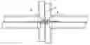
FIG. 1 is a side view of a beam provided with the coupling element of the invention;
FIG. 2 is a plan view of a coupling element inserted into the central web;
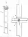
FIG. 3 is an enlarged view of the coupling appendix;
FIG. 4 is a side view thereof;
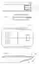
FIG. 5 is a side view of a beam with the appendix formed in one piece therewith; and
FIG. 6 is a plan view thereof.
As can be seen from the figures, the improved coupling element 2 of the invention is applied to the ends of the central web 4 of a beam of inverted T cross-section, said element being formed separately and applied to each beam part during its construction.
The coupling element comprises a substantially rectangular first portion 8 applied by traditional riveting to the ends of the central web, the portion 8 extending into a second portion 10 of lesser height which is bent substantially to V-shape with a portion 12 coplanar with the first portion 8 and with a second portion 14 comprising a tooth 16 obtained by cutting and plastic deformation, the free end of the tooth substantially facing the end of the first portion 8.
The central web 4 comprises a substantially rectangular cut-out 17 with its minor side provided with a projection 20 and with its major side having a length substantially corresponding to that of the second portion 10 of the coupling element.
In this manner the projection 20 defines two apertures 18 each suitable for engagement by the opposing part of the coupling elements.
To assemble the lattice structure, the operator inserts the V-bent element 8 of the coupling element 2 into the aperture 18 of the central web 4, so compressing together the two parts 12, 14 of the second portion 10 until the free end of the tooth 16 becomes positioned on the other side of the web, to hence retain it with the end of the first portion 8 (see FIG. 2).
When it becomes necessary to mutually disengage the beams, the operator presses the free end 14 of the V portion 10 so as to disengage the undercut formed by the tooth 16 from the edge of the aperture 18 and then axially withdraws the coupling element therefrom.
In the embodiment shown in FIGS. 5 and 6 the coupling element is obtained directly during the beam construction.
From the aforegoing it is clear that the improved coupling element according to the invention presents the advantage not only of constructional simplicity, but also of a greater ease of release by virtue of the better accessibility of the appendix part to be pressed, without having to perform unusual manoeuvres.
Claims
1. (canceled)
2. An element as claimed in claim 4 wherein the appendix is secured to the ends of the beam by riveting.
3. An element as claimed in claim 4 wherein the appendix is formed in one piece with the beam.
4. An inverted T-beam comprising:
two ends and a central web;
at least one of its ends having an appendix formed from two portions of a different height, a first inner portion extending into a second outer portion, said outer portion having the lesser height and being bent to a V-shape comprising two parts forming the two legs of said V-shape, a first part being coplanar with the first portion and the second free part comprising a tooth obtained by cutting out and plastically deforming a part of the second part, the free end of the tooth substantially facing the end of the first portion, and
at least one aperture in the central web having a height substantially corresponeding to the height of said outer portion of the appendix such that said aperture is suitable for the insertion and for the stable retention of the outer portion of the appendix of another inverted T-beam having an identical appendix by the tooth and the edge of the inner portion of said other inverted T-beam.
Images & Drawings included:
Sources:
- United States Patent and Trademark Office - verify current appl. status at the USPTO↗
Recent applications in this class:
- » 20230056851 2023-02-23
A SECONDARY PROFILE CONNECTOR FOR A SUSPENDED CEILING SYSTEM - » 20200318350 2020-10-08
Cross runner connector and cross runner connector arrangement for a suspended ceiling system - » 20160040426 2016-02-11
Suspended ceiling grid adapter - » 20150040495 2015-02-12
Channel cross member - » 20150040494 2015-02-12
Two-part channel cross member - » 20140341640 2014-11-20
SUSPENDED CEILING GRID ADAPTER - » 20140069041 2014-03-13
Suspended ceiling grid adapter - » 20130318905 2013-12-05
Two-piece modular yoke - » 20120159890 2012-06-28
Grid system for a suspended ceiling - » 20120085061 2012-04-12
Profiled Bar for Frames and Relative Frame