Plug-type connection for a ribbon conductor
US20060166523A1
2006-07-27
10/545,903
2004-02-16
Abstract:
The invention relates to a plug-type connection in which a ribbon cable (1) is inserted into a plug (3). According to the invention, the ribbon cable (1) has a marking (2).
Inventors:
- Klaus Umfahrer 2 🇩🇪 Stuttgart, Germany
- Markus Bilger 6 🇩🇪 Trossingen, Germany
- Ulf Bartholomaeus 1 🇩🇪 St. Georgen, Germany
- Josef Rottler 1 🇩🇪 Koenigsfeld, Germany
- Mathias Vollmer 1 🇩🇪 Villingen-Schwenningen, Germany
Assignee:
- SIEMENS AKTIENGESELLSCHAFT 10,711 🇩🇪 Munich, Germany
Interested in similar patents?
Get notified when new applications in this technology area are published.
Classification:
H01R13/641 » CPC main
Details of coupling devices of the kinds covered by groups or -; Means for preventing incorrect coupling by indicating incorrect coupling; by indicating correct or full engagement
H01R13/631 » CPC further
Details of coupling devices of the kinds covered by groups or -; Means for facilitating engagement or disengagement of coupling parts or for holding them in engagement; Additional means for facilitating engagement or disengagement of coupling parts, e.g. aligning or guiding means, levers, gas pressure electrical locking indicators, manufacturing tolerances for engagement only
H01R12/79 » CPC further
Structural associations of a plurality of mutually-insulated electrical connecting elements, specially adapted for printed circuits, e.g. printed circuit boards [PCBs], flat or ribbon cables, or like generally planar structures, e.g. terminal strips, terminal blocks; Coupling devices specially adapted for printed circuits, flat or ribbon cables, or like generally planar structures; Terminals specially adapted for contact with, or insertion into, printed circuits, flat or ribbon cables, or like generally planar structures; Coupling devices for flexible printed circuits, flat or ribbon cables or like structures connecting to rigid printed circuits or like structures
H05K1/00 IPC
Printed circuits
H05K1/00 IPC
Printed circuits
Description
The invention relates to a plug-type connection between a ribbon cable and a plug suitable for ribbon cables. In the prior art, plug-type apparatuses are known in which ribbon cables can be inserted into plugs without being locked in This takes place in particular manually, since it is only possible to check for a correct contact-connection automatically using electrical means.
It is therefore the object of the invention to specify a plug-type connection which can also be carried out automatically and in which inspection of the electrical contact can be dispensed with. This object is achieved by the ribbon cable being provided with a marker. Once the ribbon cable has been mounted in the plug, it is possible for the position of the marker in relation to the plug to be inspected visually and to thereby establish whether the ribbon cable has been mounted correctly. In particular, the marker may be in the form of a marker line which in a particularly advantageous manner extends at a right angle to the extent of the ribbon cable. It is thus possible for the distance between the marker line and the plug to be measured.
The invention will be explained in more detail below with reference to the figures, in which:
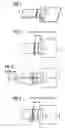
FIG. 1 shows a ribbon cable having a marker in a plug,
FIG. 2 shows the plan view of the group of components shown in FIG. 1, an optimal marked-out depth being illustrated,
FIG. 3 shows a plan view of the assembly shown in FIG. 1 in which an angular error has occurred, and
FIG. 4 shows the plan view of the assembly shown in FIG. 1, the ribbon cable having been inserted to an insufficient extent.
FIG. 1 shows a ribbon cable 1 having a marker 2 and also a plug 3 which is arranged on a printed circuit board 4 and is electrically connected to said printed circuit board 4. There is a high contrast between the marker 2 and the flexible conductor 1. In particular, in the case of light-colored flexible conductors, a black marker is particularly suitable.
FIGS. 2 to 4 also illustrate a sensor array 5 of a test device which is otherwise not illustrated. As long as the sensor array 5 coincides with the marker 2, an optimal marked-out depth of the ribbon cable can be assumed.
In FIG. 3, an angular error is detected since only parts of the sensor array 5 are covered.
In FIG. 4, an insufficient insertion depth is established since the sensor array 5 has not yet detected the marker 2.
The marker 2 may be of any desired form; it is therefore in particular also possible for colored markers to be provided only at the edges of the ribbon cable. It is also possible for the markers to be in three-dimensional form using, for example, strips or notches. However, overall it has been shown that an optical marker in the form of a continuous line can be inspected particularly easily and reliably.
The ribbon cable may have, for example, a contact pitch of 0.3 mm, 0.5 mm, 1 mm or 1.25 mm.
Claims
1. (canceled)
2. (canceled)
3. (canceled)
4. (canceled)
5. A plug-type connection, comprising means for receiving a ribbon cable is inserted into the plug, the plug being arranged on a printed circuit board and being electrically connected to the printed circuit board, wherein the ribbon cable comprises a marker.
6. The plug-type connection according to claim 5, wherein the marker is a marker line.
7. The plug-type connection according to claim 2, wherein the marker line extends at substantially right angles to the extent of the ribbon cable.
8. The plug-type connection according to claim 1, wherein marker color is in contrast to the rest of the ribbon cable.
Images & Drawings included:

Sources:
- United States Patent and Trademark Office - verify current appl. status at the USPTO↗
Recent applications in this class:
- » 20250149829 2025-05-08
CONNECTOR - » 20250132523 2025-04-24
POWER CONNECTOR - » 20250125564 2025-04-17
CABLE DETECTION USING LIGHT SENSOR - » 20250105560 2025-03-27
CONNECTOR - » 20250105559 2025-03-27
DEVICE FOR CONNECTING AN ELECTRICAL CONDUCTOR TO AN ELECTRICAL CONNECTOR, THE DEVICE BEING PROVIDED WITH A VISUAL INDICATOR OF PROPER ASSEMBLY - » 20250096506 2025-03-20
CONNECTOR AND ELECTRONIC DEVICE - » 20250079768 2025-03-06
HIGH-VOLTAGE ENERGY STORAGE QUICK CONNECTOR - » 20250023298 2025-01-16
ELECTRICAL CONNECTOR ASSEMBLY - » 20250007217 2025-01-02
CONNECTOR - » 20240429657 2024-12-26
CONNECTOR
Recent applications for this Assignee:
- » 20250166165 2025-05-22
TRAINING SYSTEMS FOR SURFACE ANOMALY DETECTION - » 20250117920 2025-04-10
SELF-SUPERVISED ANOMALY DETECTION FRAMEWORK FOR VISUAL QUALITY INSPECTION IN MANUFACTRUING - » 20250108504 2025-04-03
PLANNING HINT GENERATION FOR COLLISION FREE MOTIONS - » 20250097699 2025-03-20
NETWORK MANAGEMENT IN AN INTERNET-OF-THINGS (IOT) ENVIRONMENT - » 20250085928 2025-03-13
INTELLIGENT DEVICE EXTENSION FOR BUILDING SOFTWARE APPLICATIONS - » 20250028517 2025-01-23
SYSTEM AND METHOD FOR RELIABLE OVER-THE-AIR FIRMWARE UPDATES - » 20250004437 2025-01-02
Low Code Engineering Function Orchestrator - » 20240427304 2024-12-26
SYSTEM AND METHOD FOR ENABLING SCALABLE PROCESSING THROUGHPUT OF HIGH-VOLUME DATA ON INDUSTRIAL CONTROLLERS - » 20240419129 2024-12-19
Method and system for providing time-critical control applications - » 20240418560 2024-12-19
Calibration method for a flow measurement system, flow measurement system and computer program product