Outboard drive for boats
US20060166569A1
2006-07-27
11/306,327
2005-12-22
✅ Patent granted
US 7,226,327 B2
2007-06-05
-
-
Sherman Barsinger
2025-12-22
Abstract:
An outboard drive for boats, having a steerable underwater housing (1) which has a wing-profiled portion (2). Projecting at an approximately 90 degree angle from the aft part of one side face (31) of the wing profile is a face portion (32), the lateral extent of which amounts to about 1-2% of its distance to the steering shaft (36) of the wing profile. As a result of this construction, a lifting force will be generated during forward travel in the water. The face portion is configured on that side of the profile which produces a lifting force counter-directional to a steering force, deriving from the motor torque, upon the wing profile.
Assignee:
- AB VOLVO PENTA 29 🇸🇪 GOTHENBURG, Sweden
- AB VOLVO PENTA 1 🇺🇸 Goteborg, United States
Interested in similar patents?
Get notified when new applications in this technology area are published.
Classification:
B63H20/12 » CPC further
Outboard propulsion units, e.g. outboard motors or Z-drives; Arrangements thereof on vessels; Means enabling movement of the position of the propulsion element, e.g. for trim, tilt or steering; Control of trim or tilt Means enabling steering
B63H20/34 » CPC further
Outboard propulsion units, e.g. outboard motors or Z-drives; Arrangements thereof on vessels; Housings comprising stabilising fins, foils, anticavitation plates, splash plates, or rudders
B63H5/10 » CPC further
Arrangements on vessels of propulsion elements directly acting on water of propellers of more than one propeller of coaxial type, e.g. of counter-rotative type
B63H20/08 IPC
Outboard propulsion units, e.g. outboard motors or Z-drives; Arrangements thereof on vessels Means enabling movement of the position of the propulsion element, e.g. for trim, tilt or steering; Control of trim or tilt
B63H5/125 » CPC main
Arrangements on vessels of propulsion elements directly acting on water of propellers movably mounted with respect to hull, e.g. adjustable in direction, e.g. podded azimuthing thrusters
B63H5/20 IPC
Arrangements on vessels of propulsion elements directly acting on water of propellers of emergency propellers, e.g. arranged at the side of the vessel movable from a working position to a non-working position
B63H20/32 IPC
Outboard propulsion units, e.g. outboard motors or Z-drives; Arrangements thereof on vessels Housings
Description
CROSS-REFERENCE TO RELATED APPLICATIONSThe present application is a continuation patent application of International Application No. PCT/SE2004/000600 filed 20 Apr. 2004 which is published in English pursuant to Article 21(2) of the Patent Cooperation Treaty, and which claims priority to Swedish Application No. 0301 802-5 filed 23 Jun. 2003. Said applications are expressly incorporated herein by reference in their entireties.
TECHNICAL FIELD OF THE INVENTIONThe present invention relates to an outboard drive for boats that include an underwater housing which has a wing-profiled portion, having an aft portion configured non-symmetrically with respect to a vertical plane of symmetry of the wing profile. The outboard drive is intended to be mounted in a boat's hull for rotation about a substantially vertical steering shaft and a vertical drive shaft is mounted rotatably in the underwater housing concentrically with the steering shaft. At least one substantially horizontal propeller shaft is included that is rotatably mounted in the underwater housing and which, via a bevel gear encased in the underwater housing, is drivably connected to a lower end of the drive shaft. An upper end of the drive shaft is intended to be connected to a drive unit disposed on the inner side of the boat's hull.
BACKGROUND OF THE INVENTIONTo a rotatable underwater housing of an outboard drive for boats, torque is transmitted from the motor coupled to the outboard drive via a bevel gear mounted on the inner side of the boat's hull, so that the underwater housing, under load, strives to rotate in the same direction as the rotational direction of the vertical drive shaft. Outboard drives of the type described above are used, in particular, in boats from 40 feet and upward, which have high-powered motors with high torque, for example from about 600 Nm and above. This means that the underwater housing is constantly subjected, while the boat is in motion, to a relatively high steering torque that somehow has to be balanced.
A simple and known method is, of course, quite simply to dimension the steering machinery of the drive large enough so that it is able to absorb the forces to which the motor torque gives rise, together with the steering forces when the boat yaws. This means, however, that the steering machinery has to be more generously proportioned than would be required if it merely needed to exert the force to rotate the underwater housing during yawing. Another way is to dimension the underwater housing with a very large surface area behind the steering shaft of the underwater housing. Finally, the underwater housing can be configured with an asymmetrical profile, for example with a curved aft part, which is also known.
To provide the drive with steering machinery that is more powerful than that required for the actual steering is an expensive solution. This also applies to an underwater housing having a large surface area.
Moreover, such an underwater housing increases the resistance in the water and is additionally given an unnecessary amount of weight. Also, a drive having a curved aft edge on the wing-shaped underwater housing is more difficult to produce than a symmetrical drive and the dimensional control is not as good.
SUMMARY OF INVENTIONAn object of the present invention is to produce an outboard drive of the type introduced above, and which is asymmetrically configured so as to balance the steering force from the motor torque, but in a new way which is easy to control dimensionally and which has an insignificant effect upon production costs compared with a symmetrical drive, while simultaneously resulting in an underwater housing with low drag resistance.
This is achieved according to the invention by virtue of the fact that the wing profile has opposing side faces, of which one face has a first face portion, which extends from the fore edge of the wing profile aftward toward the aft edge of the wing profile, a second face portion, which, with a sharp offset, angles out sideways from the main portion at a distance from the aft edge, and a third face portion, which adjoins the aft edge.
Surprisingly, an angled-out face portion of this kind, which projects sideways by a distance only amounting to one or two percent of the total side face of the wing portion behind the steering shaft, has proved sufficient to balance the steering forces from the motor torque.
BRIEF DESCRIPTION OF THE DRAWINGSThe invention is described in greater detail with reference to illustrative embodiments shown in the accompanying drawings, in which:
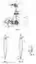
FIG. 1 shows a diagrammatic perspective view of a known outboard drive;
FIG. 2 shows a known asymmetrical cross-sectional profile of the underwater housing for a drive of the type shown in FIG. 1;
FIG. 3a shows a first embodiment of the cross-sectional profile of a drive configured according to the present invention; and
FIG. 3b shows a second embodiment of that region of the profile which is ringed in FIG. 3a.
DETAILED DESCRIPTIONThe outboard drive diagrammatically shown in FIG. 1 has an underwater housing 1 having a wing-shaped top part 2 and a torpedo-like bottom part 3. Mounted in the housing 1 is a vertical drive shaft 4, which, via an upper bevel gear 5 in a housing 6 on the inner side of a boat's hull (not shown), can be driven by a motor (not shown). The drive shaft 4 drives, via a bevel gear 7 in the torpedo-like bottom part 3 of the housing 1, two counter-rotating propeller shafts 8 and 9, of which the shaft 9 is a tubular shaft through which the shaft 8 extends. On each of the shafts 8 and 9 is mounted a respective draw propeller 10 and 11.
A bearing housing with steering spindle for pivotal mounting of the underwater housing 1 on the outer side of the bottom of a boat's hull is denoted by 12. Pivoting of the underwater housing is realized with the aid of a steering motor (not shown), which can be electric or hydraulic.
When an input shaft 13 is driven in the rotational direction indicated by the arrow “a”, the vertical drive shaft 4 is driven, via the bevel gear 5, in the rotational direction indicated by the arrow “b”, the torque from the motor giving rise to a steering force upon the underwater housing 1 in the direction indicated by the arrow “c”. This steering force can be balanced in a known manner if the wing-shaped housing part 2 is configured asymmetrically, for example with a profile 20 as shown in FIG. 2 and having a slightly curved aft portion 21. A lifting force is thereby created, which is counter-directional to the steering force.
According to the present invention, a corresponding lifting force can be produced with a wing-shaped housing part 2, which in one embodiment has the profile 30 shown in FIG. 3a. Here, projecting sideways from a main portion 31 of one side face of the profile 30 is a face portion 32, which adjoins the aft edge 33 of the wing profile via a face portion 34a. In the illustrated embodiment, the face portion 32 forms an approximately 90 degree angle with the plane of symmetry 35 of the wing profile. A lateral extent amounting to one to two percent of its distance to the steering shaft 36 of the profile has herein proved sufficient to produce the force necessary to balance the steering force from the motor torque. In the illustrated embodiment, this is about one and one-half percent. The distance between the face portion 32 and the aft edge 33 can be between two and six percent of the distance between the steering shaft 36 and the aft edge. In the illustrated embodiment, this is about five percent.
FIG. 3b shows an alternative embodiment of the aft portion of the wing profile which is ringed in FIG. 3a, which embodiment differs from the profile in FIG. 3a mainly by virtue of the fact that the face portion 32 adjoins the aft edge 33 via an angled face portion 34b, 34c. Here, the face portion 32 is situated closer to the aft edge 33 than in the embodiment in FIG. 3a. In the embodiment according to FIG. 3b, the face portion 32 can be a surface on a separate rail, which, expediently, is fixedly mounted on the aft edge 33 of the wing-shaped top part 2 of the underwater housing.
Claims
What is claimed is:1. An outboard drive for boats, comprising an underwater housing (1) which has a wing-profiled portion (2), having an aft portion configured non-symmetrically with respect to a vertical plane of symmetry (35) of the wing profile, and is intended to be mounted in a boat's hull for rotation about an at least substantially vertical steering shaft (36), a vertical drive shaft (4) mounted rotatably in the underwater housing concentrically with the steering shaft, and at least one at least substantially horizontal propeller shaft (8,9), which is mounted rotatably in the underwater housing and which, via a bevel gear encased in the underwater housing, is drivably connected to a lower end of said drive shaft, the upper end of which is intended to be connected to a drive unit disposed on the inner side of the boat's hull, wherein the wing profile (2) has opposing side faces, of which one face has a first face portion (31), which extends from the fore edge of the wing profile aftward toward the aft edge (33) of the wing profile, a second face portion (32), which, with a sharp offset, angles out sideways from the first portion at a distance from the aft edge, and a third face portion (34a; 34b, 34c), which adjoins the aft edge.
2. The outboard drive as recited in claim 1, wherein said second face portion (32) forms an approximately 90 degree angle with the plane of symmetry (35) of the wing profile.
3. The outboard drive as recited in claim 1, wherein said second face portion (32) has a width amounting to about 1-2 percent of its distance to the steering shaft (36) of the wing profile.
4. The outboard drive as recited in claim 1, wherein said second face portion (32) has a distance to the aft edge (33) of the wing profile amounting to about 2-6 percent of the distance between the steering shaft (36) and the aft edge.
5. The outboard drive as recited in claim 1, wherein said wing-profiled portion (2) forms an upper part of the underwater housing (1) and adjoins a lower, torpedo-like portion (3) encasing the bevel gear (7).
6. The outboard drive as recited in claim 1, wherein said propeller shaft (8, 9) has an end which projects from the fore end portion of the underwater housing and supports a draw propeller (10, 11).
7. The outboard drive as recited in claim 1, further comprising two concentric propeller shafts (10, 11) mounted in the underwater housing (1) and that are drivably connected to a double bevel gear for driving their respective draw propeller (10, 11) in opposite directions.
8. The outboard drive as recited in claim 1, wherein said steering shaft of the underwater housing (1) is situated at a distance from the fore edge of the wing profile amounting to about 15-20 percent of the total length of the wing profile (30).
9. An outboard drive for boats, comprising:
an underwater housing (1) having a wing-profiled portion (2) that includes an aft portion configured non-symmetrically with respect to a vertical plane of symmetry (35) of the wing-profiled portion (2);
a vertical drive shaft (4) mounted rotatably in the underwater housing concentrically with the steering shaft;
at least one substantially horizontal propeller shaft (8,9) is rotatably mounted in the underwater housing and which, via a bevel gear encased in the underwater housing, is drivably connected to a lower end of said drive shaft, an upper end of said drive shaft is configured to be connected to a drive unit disposed on the inner side of the boat's hull; and
said wing-profiled portion (2) comprises opposing side faces, of which one has (i) a first face portion (31) which extends from the fore edge of the wing-profiled portion (2) aftward toward the aft edge (33) thereof, (ii) a second face portion (32) that has a sharp offset that angles out sideways from the first portion at a distance from the aft edge and (iii) a third face portion (34a, 34b, 34c) which adjoins the aft edge.
10. The outboard drive as recited in claim 9, wherein said second face portion (32) forms an approximately 90 degree angle with the plane of symmetry (35) of the wing profile.
11. The outboard drive as recited in claim 9, wherein said second face portion (32) has a width amounting to about 1-2 percent of its distance to the steering shaft (36) of the wing profile.
12. The outboard drive as recited in claim 9, wherein said second face portion (32) has a distance to the aft edge (33) of the wing profile amounting to about 2-6 percent of the distance between the steering shaft (36) and the aft edge.
13. The outboard drive as recited in claim 9, wherein said wing-profiled portion (2) forms an upper part of the underwater housing (1) and adjoins a lower, torpedo-like portion (3) encasing the bevel gear (7).
14. The outboard drive as recited in claim 9, wherein said propeller shaft (8, 9) has an end which projects from the fore end portion of the underwater housing and supports a draw propeller (10, 11).
15. The outboard drive as recited in claim 9, further comprising two concentric propeller shafts (10, 11) mounted in the underwater housing (1) and that are drivably connected to a double bevel gear for driving their respective draw propeller (10, 11) in opposite directions.
16. The outboard drive as recited in claim 9, wherein said steering shaft of the underwater housing (1) is situated at a distance from the fore edge of the wing profile amounting to about 15-20 percent of the total length of the wing profile (30).
Images & Drawings included:

Sources:
- United States Patent and Trademark Office - verify current appl. status at the USPTO↗
Similar patent applications:
- » 20050227553
Method of steering a boat with double outboard drives and boat having double outboard drives - » 20070224893
Method of steering a boat with double outboard drives and boat having double outboard drives - » 20050272321
Boat hull with outboard drive and outboard drive for boats - » 20050202735
Outboard drive for boats - » 20070270053
Outboard drive for boats
Recent applications in this class:
- » 20240383594 2024-11-21
A PROPULSION UNIT FOR LIFEBUOY - » 20240343365 2024-10-17
PROPULSION SYSTEM FOR A MARINE VESSEL AND A USE OF A SLIP CLUTCH ASSEMBLY - » 20240227998 2024-07-11
WATERCRAFT PROPULSION SYSTEM, AND WATERCRAFT - » 20240132189 2024-04-25
WATERCRAFT PROPULSION SYSTEM, AND WATERCRAFT - » 20230227138 2023-07-20
Marine power plant assembly - » 20230150632 2023-05-18
Propulsion devices and methods of making propulsion devices that align propeller blades for marine vessels - » 20230070348 2023-03-09
A VESSEL - » 20220266968 2022-08-25
Propulsion devices and methods of making propulsion devices that align propeller blades for marine vessels - » 20220266967 2022-08-25
Devices and methods for making devices for supporting a propulsor on a marine vessel - » 20220055724 2022-02-24
Mounting arrangement for a propulsion unit
Recent applications for this Assignee:
- » 20220348301 2022-11-03
Electrical steering system in a marine vessel and a method for controlling such a steering system - » 20220090637 2022-03-24
Multi-plate clutch transmission and marine vehicle including a multi-plate clutch transmission - » 20200086962 2020-03-19
Propeller drive assembly - » 20200001959 2020-01-02
Large outboard motor for marine vessel application and related methods of making and operating same - » 20200001958 2020-01-02
Large outboard motor for marine vessel application and related methods of making and operating same - » 20190276122 2019-09-12
Outboard motor lighting system - » 20190202539 2019-07-04
Cooling water drain system for a marine engine - » 20190135398 2019-05-09
Large outboard motor including variable gear transfer case - » 20190054991 2019-02-21
Propeller drive assembly and a screw pump for a water vessel - » 20170259896 2017-09-14
Outboard motor including one or more of cowling, water pump, fuel vaporization suppression, and oil tank features