Adjustable tool storage tray
US20060169859A1
2006-08-03
11/045,398
2005-01-28
Abstract:
A tool storage tray assembly includes a bracket assembly enabling attachment of the tray assembly to a hoist arm of a vehicle hoist at the upper end of a depending vertical tube of the tray assembly. A separate tray bracket attached to a tray is slidably mounted on the lower end of the tube. The tray bracket enables vertical movement of the tray along the length of the tube and rotation of the tray about the axis of the tube. Thus, the tray is adjustable vertically as well as about the axis of the vertical tube or shaft.
Inventors:
- Randall J. Ploeger 15 🇺🇸 Clarinda, IA, United States
- Raymond Veasey 1 🇺🇸 Cranston, RI, United States
- James C. Draper 1 🇺🇸 Waterbury, CT, United States
Assignee:
- The Lisle Corporation 3 🇺🇸 Clarinda, IA, United States
Interested in similar patents?
Get notified when new applications in this technology area are published.
Classification:
B25H5/00 » CPC main
Tool, instrument or work supports or storage means used in association with vehicles; Workers' supports, e.g. mechanics' creepers
B25H3/06 » CPC further
Storage means or arrangements for workshops facilitating access to, or handling of, work tools or instruments Trays
A47B23/00 IPC
Bed-tables; Trays; Reading-racks; Book-rests, i.e. items used in combination with something else
Description
BACKGROUND OF THE INVENTIONIn a principal aspect the present invention relates to an adjustable tool storage tray, particularly adapted for utilization in combination with vehicle hoists of the type that are used for vehicle servicing and vehicle repair.
Auto mechanics, technicians and the like typically may need to position a motor vehicle upon a hoist in order to efficiently undertake repair of the vehicle. Generally, such hoists include a track mounted on a vertical support shaft or a series of projecting arms extending from a center support shaft. In versions having multiple arms, the arms are appropriately positioned against the vehicle undercarriage and then the central shaft is hydraulically or otherwise vertically driven to raise the vehicle to an appropriate height for servicing. The appropriate height may be only a few feet inasmuch as the servicing is directed to brake repair, for example. Alternatively, the vehicle may be raised to a height of 4, 5, or 6 feet in order to access the undercarriage of the vehicle, for example, to repair the emission system or otherwise repair vehicle component parts accessible only from the bottom or undercarriage.
Typically, it is necessary to have a variety of tools available when servicing a vehicle either from its undercarriage or otherwise positioned on a hoist. Thus, a tool cabinet, chest or tray is deemed desirable for positioning and storage of available tools. Heretofore, there have been obtained various patents directed to tool tray constructions used in combination with a hoist. For example, U.S. Pat. No. 3,983,821 entitled “Mechanic's Tray Assembly” issued Oct. 5, 1976 discloses a typical tray into which tools may be placed. The tray assembly is attached to the center pivot construction or shaft assembly of the vehicle service rack or hoist. The tray assembly includes an articulated arm to support a tool tray.
While such a prior art construction is deemed useful and beneficial, nonetheless there has remained the need for improved or alternative tool tray designs that will be especially useful in combination with a hoist. Such needs inspired the development of the present invention.
SUMMARY OF THE INVENTIONBriefly, the present invention comprises a storage tray assembly wherein a tray is constructed for attachment to a tray bracket assembly. Any one of a number of tray styles, shapes and designs may thus be attached to the tray bracket assembly. The tray bracket assembly is, in turn, slidably mounted on a generally vertical cylindrical tube so that the bracket assembly and attached tray may be moved vertically along the length of the tube. Additionally, the bracket assembly and attached tray may be pivoted around the tube to alter the position of the tray and thus enhance accessibility and utility. A locking mechanism or support mechanism is provided to maintain the tray bracket assembly and tray at a fixed position along the generally vertical tube or shaft upon which the tray bracket assembly and tray are positioned. At the top end of the generally vertical shaft or tube, a second adjustable bracket assembly is provided.
This second bracket assembly is designed and constructed to attach to a projecting arm of a hoist.
Thus, the second or hoist attachment bracket assembly includes a clamping mechanism and associated support members to insure appropriate balance of the second bracket assembly as it supports the attached tube, tray bracket assembly and tray.
In use, the upper or hoist attachment bracket assembly is tightly attached to the arm of a vehicle hoist. The vertical tube, which is positioned laterally with respect to the hoist bracket assembly, may then be positioned so as to provide for easy access to the tray. The tray, by virtue of the tray bracket assembly, may be adjusted in relative height or vertically as well as rotated about the axis of the tube or shaft. Thus, when a mechanic is working on the vehicle, for example, on wheels or brakes, it may be appropriate to raise the tool storage tray to access the tools. However, when the vehicle hoist is raised above the head of the mechanic or technician, the tool tray may be lowered and pivoted to a position where it is easy for the mechanic or serviceman to access the contents of the tool tray. The tray assembly, thus, has a wide range of applicability with respect to the various kinds of hoists available and with respect to the use and repair job which is being undertaken by a technician or auto mechanic.
Thus, it is an object of the invention to provide an improved tool storage tray assembly, particularly useful in combination with or as an adjunct to a vehicle hoist assembly.
A further object of the invention is to provide a tool storage tray assembly which provides for a tool tray which may be adjusted vertically in height as well as rotated about a generally vertical axis to enhance accessibility.
Another object of the invention is to provide a tool tray assembly for storage of tools wherein a variety of storage trays of different shape, size and configuration may be utilized.
A further object of the invention is to provide a tool storage tray assembly which is easily adjusted, rugged, and economical.
These and other objects, advantages and features of the invention will be set forth in the detailed description which follows.
BRIEF DESCRIPTION OF THE DRAWINGIn the detailed description which follows, reference will be made to the drawing comprised of the following figures:
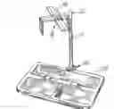
FIG. 1 is an isometric view of the tray assembly of the invention wherein the tray is positioned on a hoist in a generally partially lowered position;
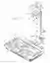
FIG. 2 is an isometric view wherein the tool tray assembly of the invention is attached to an arm of a vehicle hoist and the tool tray is positioned in a raised position;
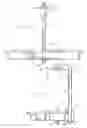
FIG. 3 is a front side elevation of the tool tray assembly of the invention;
FIG. 4 is an side view of the tool tray assembly of FIG. 3; and
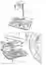
FIG. 5 is an isometric view of the tool tray assembly which is partially exploded and wherein the tray is separated from the bracket assemblies.
DESCRIPTION OF THE PREFERRED EMBODIMENTReferring to the figures, the tool storage tray assembly of the invention comprises, in a preferred embodiment, a generally cylindrical tube 10 in the range of 12-18 inches in length and having a diameter in the range of ⅜-¾ inch. Preferably the tube 10 is a hollow metal cylindrical tube. The tube 10 includes a vinyl cap 12 at its top end and defines a generally vertical axis 14.
An upper or hoist attachment bracket assembly 16 is welded to the upper end of the tube 10. A tray bracket assembly 18 is slidably mounted on the lower end of the tube 10 by sliding upwardly from the lower end to a desired or adjusted position. The tray bracket assembly 18 is provided for attachment to and support of a tray 20. The upper bracket assembly 16 is for attachment of the entire tool storage tray assembly to the arm of a vehicle hoist such as attachment to an arm 22 in FIG. 2.
The upper bracket assembly 16 and the tray bracket assembly or lower bracket assembly 18 are each fabricated from plate or sheet metal in the preferred embodiment. However, the components may be fabricated from other materials such as molded plastic materials or composites. The upper bracket assembly 16 includes a first generally horizontal arm 24 which is welded to the tube 10 and projects laterally from the axis 14. A second L-shaped upper bracket member 26 includes an arm 28 which, when assembled with the bracket arm 24, comprises an extension of that arm 24. The bracket member 26 further includes a downwardly pending run or section 30. A cross bracket member 32 is aligned at a substantially right angle to the bracket member 24 and bracket member 26. A bolt 34 and bracket tightening nut 36 cooperate to engage and hold the bracket members 26, 24 and 32 tightly together in a desired fixed position. For example, referring to FIG. 2, the bracket members are tightened to fit along the side edges as well as top of a hoist arm 22. Note that the transverse bracket member 32 provides stability so that the tube 10, which is held by that upper bracket assembly 16, will be held in a generally fixed position and not swing from side to side in an undesirable fashion.
Other configurations of the upper bracket assembly 16 may be utilized in order to maintain the stability and attachment to the tube 10. That is, the bracket design for the upper bracket assembly 16 may be varied to accomplish the goal or objective and function of maintaining the tube 10 spaced slightly laterally from the hoist arm 22 and generally rigidly positioned with respect thereto and to maintain a desired generally vertical orientation of tube or shaft 10.
The tray bracket assembly 18 is comprised of, a generally horizontal upper bracket member element 40 and a downwardly depending member or element 42 connected to a second spaced generally horizontal bracket member or element 44. The bracket elements 40 and 44 are generally parallel in the embodiment depicted and each includes an aligned passage or opening 46 and 48, respectively, therethrough sized so that the bracket 18 may be slidably mounted on the tube 10. Lower bracket element 44 extends horizontally, in the preferred embodiment, for a greater distance than the upper bracket element 40. A transverse or cross bracket element 50 is affixed, for example, by rivets or welding to the extended lower bracket element 44. The upper bracket element 40 includes a second outer passage or opening for receipt of a pin; namely, an opening 52 for receipt of a pin 54 therethrough. Pin 54 fits through the opening 52 and into a passage or opening 58 in the top rim of tray 20. The upper element 40 is spaced from the lower element 44 so that the bracket assembly 18 will appropriately bridge the thickness of the tray 20 with the lower element 44 and cross member 50 positioned snuggly against the bottom section of the tray 20 and the upper element 40 positioned snuggly against a top face of the tray 20 fasteners 51 fit through passages in the bottom of tray 20 and serve to attach tray 20 to cross bracket 50. The tray 20 is thus maintained in a stable condition by the bridging elements 40 and 44 with the pin 54 fitted in the opening 58 through the passage 52 to retain the tray 20 in the tray bracket assembly 18. The tray 20 is maintained at a desired or fixed distance from the generally vertical axis through the openings 46 and 48.
Various types of trays 20 may be utilized. That is, the tray 20 may include various troughs, such as a trough 60, for holding tools. The size, shape, color and the like of the tray 20 may be varied according to the tools and other desired functions to be performed by the tray 20. Importantly, the tray 20 is affixed to a bracket assembly 18; namely, tray bracket assembly 18 and may be easily removed and replaced.
Further, the tray bracket assembly 18 is mountable on the tube 10 in a slidable fashion so that the height of the tray 20 may be adjusted to accommodate the needs of the user of the tool storage tray assembly. Once the height is adjusted, a locking pin 70 may be inserted through one of a series of lateral passages 72 and 74 provided in the tube 10 to hold the tray bracket assembly 18 and associated tray 20 in a fixed position. That is, the pin 70 will be positioned so as to be beneath the tray bracket assembly 18 and thus hold the tray bracket assembly 18 at a fixed elevated position on the tube 10. When in this elevated position, the tray bracket assembly 18 is still pivotal about the axis 14 of the tube 10. Of course, the pin 70 may be removed and the vertical height of the tray 20 adjusted according to needs.
For example, as depicted in FIG. 1, the tray 20 is at a lower position on the tube 10. Such a lower position may be desirable when the hoist to which the tool storage tray assembly is attached is raised to a highest or higher level and the mechanic necessarily needs to have ease of access to tools within the tray 20. Thus, the tray 20 may be lowered relative to a hoist arm 22 to facilitate access to tools within the tray 20.
On the other hand, as depicted in FIG. 2, when the hoist is raised partially upward, for example, to service the brake system of a wheel, the tray 20 can be maintained at a level upwardly along the tube 10 as depicted for ease of access again, for example, at waist level or an equivalent level as desired by the mechanic. Thus, adjustability of the tray 20 to a desired level along the axis of the tube 10 is maintained. Additionally, the tray 20 may be rotated about the axis 14 to a desired orientation or position.
The adjustability of the upper bracket assembly 16 permits attachment of the device to any of a series of various types of hoists having various types and sizes of hoist arms.
Additionally, the tool storage assembly of the invention may be utilized in other environments wherein it can be easily attached and held on an arm or other member and wherein adjustability of the tray 20 in terms of its height can be obtained. The tray 20, as previously mentioned, may be altered or changed merely by removing the pin 54 and the two bolts or fasteners 51 through the tray 20 and cross member 50 and then substituting a new tray in place thereof.
Various other modifications and changes may be undertaken while not departing from the spirit and scope of the invention. The orientation of the tube 10 may be altered but the function of preserving the ability to adjust the relative position of a tray 20 along the length of the tube 10 as sell as to rotate the tray 10 about the axis of a tube 10 is a desired functional aspect of the invention to be maintained. Various types of bracket assemblies may also be utilized to accomplish the goals and objectives of the invention. The invention is therefore to be limited only by the following claims and equivalents thereof.
Claims
What is claimed is:1. A tool storage tray assembly comprising, in combination:
a generally cylindrical tube member having an upper end, a longitudinal axis and a lower end;
an upper bracket assembly attached to the upper end of the tube member, said upper bracket assembly projecting generally laterally from the longitudinal axis, said upper bracket assembly including adjustably spaced bracket gripping members and a fastening mechanism to fix the bracket members in position relative to one another for mounting the assembly to a fixture and thereby support the tube member;
a tray support bracket assembly including a first generally laterally projecting tray support member and a second, spaced generally laterally projecting tray support member spaced from the first tray support member, each said first and second tray support members including a tube passage aligned to enable axial sliding and rotational positioning of the tray support bracket assembly on the tube;
at least two detent positions of the tray support bracket on said tube;
a retention mechanism for retaining the tray support bracket at a generally fixed detent position relative to the longitudinal axis; and
a tray supported by the tray bracket assembly.
2. The tray assembly of claim 1 wherein the detent positions comprise a generally transverse passage in the tube and a pin member for placement in the passage to engage and support the tray support bracket.
3. The tray assembly of claim 1 wherein the tray support members comprise spaced, generally planar plate members for positioning on the tray, and a fastening member for attaching at least one plate member to the tray.
4. The tray assembly of claim 1 wherein the upper bracket assembly includes a slidable gripping member and a fixed gripping member, said fixed gripping member attached to the tube member and said slidable gripping member adjustably attached to the fixed gripping member by said fastening mechanism.
5. The tray assembly of claim 4 further including a stabilizing member attached to and projecting from one of the gripping members for engaging the fixture.
6. The tray assembly of claim 1 wherein the tray includes a top side with a pin receiving passage, and wherein said first tray support member includes a passage that may be aligned with the tray pin receiving passage, and further including a removable pin fitted through the passages to hold the tray.
Images & Drawings included:
Sources:
- United States Patent and Trademark Office - verify current appl. status at the USPTO↗
Recent applications in this class:
- » 20250153341 2025-05-15
CREEPER WITH ENHANCED MOBILITY - » 20250091195 2025-03-20
MECHANIC'S CREEPER WITH LIGHTS - » 20250083299 2025-03-13
CREEPER WTIH RAISED POSITION AND LOWERED POSITION AND WITH HIDDEN HINGE ASSEMBLY - » 20250042014 2025-02-06
BODY SUPPORT DEVICE - » 20240424662 2024-12-26
MULTI-CONFIGURATION MECHANIC'S CREEPER - » 20240399562 2024-12-05
FOLDABLE LYING CREEPER - » 20240375265 2024-11-14
Illuminated Mechanic's Creeper Device - » 20240326234 2024-10-03
CREEPER HEADREST ATTACHMENT SYSTEM - » 20240083015 2024-03-14
Swing arm system and method - » 20240033897 2024-02-01
Tools and parts caddy for man-lifts
Recent applications for this Assignee:
- » 20050066780 2005-03-31
Oxygen sensor removal and installation tool - » 20050022380 2005-02-03
Steering gear pitman-arm spreader tool