Battery pack-detecting charger
US20060176013A1
2006-08-10
11/398,697
2006-04-05
✅ Patent granted
US 7,405,536 B2
2008-07-29
-
-
Edward Tso
2026-04-05
Abstract:
A charger having a controller with an input and an output, a first terminal for connecting a battery pack to the controller, a connecting line disposed between the first terminal and the input of the controller, a current source connected to the controller for providing power to the battery pack. The current source provides power to the battery pack via the connecting line. The controller sends a pulse signal unto the connecting line via the output, so that the controller can determine whether the battery pack is connected to the charger by the presence of the pulse signal in the input of the controller.
Assignee:
- Black& Decker Inc. 1,427 🇺🇸 Newark, DE, United States
Interested in similar patents?
Get notified when new applications in this technology area are published.
Classification:
H02J7/0029 » CPC main
Circuit arrangements for charging or depolarising batteries or for supplying loads from batteries with safety or protection devices or circuits
H01M10/4257 » CPC further
Secondary cells; Manufacture thereof; Methods or arrangements for servicing or maintenance of secondary cells or secondary half-cells; Structural combination with electronic components, e.g. electronic circuits integrated to the outside of the casing Smart batteries, e.g. electronic circuits inside the housing of the cells or batteries
H02J9/007 » CPC further
Circuit arrangements for emergency or stand-by power supply, e.g. for emergency lighting using a power saving mode Detection of the absence of a load
Y02E60/10 » CPC further
Enabling technologies; Technologies with a potential or indirect contribution to GHG emissions mitigation Energy storage using batteries
Y02E60/10 » CPC further
Enabling technologies; Technologies with a potential or indirect contribution to GHG emissions mitigation Energy storage using batteries
Y10S320/12 » CPC further
Electricity: battery or capacitor charging or discharging Precharging analysis, e.g. determining presence of battery
H02J7/00 IPC
Circuit arrangements for charging or depolarising batteries or for supplying loads from batteries
H01M10/46 IPC
Secondary cells; Manufacture thereof; Methods or arrangements for servicing or maintenance of secondary cells or secondary half-cells Accumulators structurally combined with charging apparatus
Description
FIELD OF THE INVENTIONThis invention relates generally to battery chargers and more particularly to battery chargers with protection circuitry.
BACKGROUND OF THE INVENTIONThe battery packs for portable power tools, outdoor tools and certain kitchen and domestic appliances may include rechargeable batteries, such as lithium, nickel cadmium, nickel metal hydride and lead-acid batteries, so that they can be recharged rather than be replaced. Thereby a substantial cost saving is achieved.
It is preferable to provide a charger that recognizes when a battery pack has been connected in order to begin charging.
SUMMARY OF THE INVENTIONIn accordance with the present invention, an improved battery pack charger is employed. The charger includes a controller having an input and an output, a first terminal for connecting a battery pack to the controller, a connecting line disposed between the first terminal and the input of the controller, a current source connected to the controller for providing power to the battery pack, the current source providing the power to the battery pack via the connecting line, wherein the controller sends a pulse signal unto the connecting line via the output, whereby the controller determines whether the battery pack is connected to the charger by the presence of the pulse signal in the input of the controller.
Additional features and benefits of the present invention are described, and will be apparent from, the accompanying drawings and the detailed description below.
BRIEF DESCRIPTION OF THE DRAWINGSThe accompanying drawings illustrate preferred embodiments of the invention according to the practical application of the principles thereof, and in which:
FIG. 1 is a simplified block diagram of a battery pack and charger;
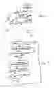
FIG. 2 is a flowchart showing a method according to the present invention;
FIG. 3 is a schematic diagram of the charger according to the present invention.
DETAILED DESCRIPTIONThe invention is now described with reference to the accompanying figures, wherein like numerals designate like parts.
Referring to FIGS. 1-2, a battery pack 10 is connected to a charger 20. Battery pack 10 may comprise a plurality of battery cells 11 connected in series and/or parallel, which dictate the voltage and storage capacity for battery pack 10. Battery pack 10 may include three battery contacts: first battery contact 12, second battery contact 13, and third battery contact 14. Battery contact 12 is the B+ (positive) terminal for battery pack 10. Battery contact 14 is the B− or negative/common terminal. Battery contact 13 is the S or sensing terminal. Battery contacts 12 and 14 receive the charging current sent from the charger 20 (preferably from current source 22, as discussed below) for charging the battery pack 10.
As shown in FIG. 1, the battery cells 11 are connected between the battery contacts 12 and 14. In addition, preferably connected between battery contacts 13 and 14 is a temperature sensing device 15, such as a negative temperature co-efficient (NTC) resistor, or thermistor, RT. The temperature sensing device is preferably in closer proximity to the cells 11 for monitoring of the battery temperature. Persons skilled in the art will recognize that other components, such as capacitors, etc., or circuits can be used to provide a signal representative of the battery temperature.
The charger 20 preferably comprises a controller 21, which in turn includes positive terminal (B+) 17 and negative (B−) terminal 18, which are coupled to battery pack 10 via battery contacts 12 and 14, respectively. The positive terminal may also act as an input, preferably an analog/digital input A/D, in order for the controller 21 to detect the battery pack voltage. In addition, the controller 21 may include another input TC, preferably an analog/digital input, which is coupled to the temperature sensing device 15 via the third battery contact 13 (S). This allows the controller 21 to monitor the battery temperature.
Controller 21 may include a microprocessor 23 for controlling the charging and monitoring operations. Controller 21 may control a charging power source for providing power to the battery pack 10, such as current source 22 that provides current to battery pack 10. This current may be a fast charging current and/or an equalization current. Current source 22 may be integrated within controller 21.
Controller 21 may have a memory 25 for storing data. Memory 25 may be integrated within controller 21 and/or microprocessor 23.
Controller 21 preferably has a pulse output PO, which sends a pulse signal unto the same line that sends power to the battery pack 10. The pulse signal may have an amplitude of 5 volts. Preferably the pulse signal generated by the controller 21 goes through a diode D23 and/or a resistor R54.
With such arrangement, controller 21 can determine whether a battery pack 10 has been connected to the charger 20. FIG. 2 is a flowchart illustrating the process for determining whether a battery pack 10 has been connected to the charger 20.
First, the current source 22 must be off (ST1). The controller 21 then sends a pulse signal via pulse output PO (ST2).
The controller 21 then checks whether the input A/D has received a pulse (ST3). If a pulse was received, a battery pack 10 is not connected to the charger 20.
On the other hand, if a pulse was not received, the controller 21 would interpret this to mean that a battery pack 10 is connected to the charger 20. Persons skilled in the art will recognize that the voltage at input A/D will be substantially constant since resistor R54 and diode D23 will not allow a significant current to generate an AC signal across the battery. Since the pulse was not received, controller 21 would then start charging battery pack 10 by turning on current source 22 (ST4).
Controller 21 then senses the battery voltage V0 via input A/D (ST5). Controller 21 compares battery voltage V0 to a certain threshold X (ST6). If battery voltage V0 is below threshold X, charging continues and controller 21 continues to sense and compare the battery voltage V0.
If battery voltage V0 exceeds (or is equal to) threshold X, controller 21 then assumes that the battery pack 10 has been removed from charger 20 and stops charging by turning the current source off. Persons skilled in the art will recognize that it is preferable to provide a relatively high threshold so as to not prematurely terminate charging, resulting in an undercharged battery pack. Accordingly, it is preferable to provide a threshold of at least 30 volts.
FIG. 3 is an exemplary schematic diagram of the charger of FIG. 1. Preferably, the values of the different components of are as follows:
| C1 | 0.1 microfarads |
| C2A | 1,000 microfarads |
| C2B | 1,000 microfarads |
| C2C | 1,000 microfarads |
| C3 | 0.1 microfarads |
| C5 | 102 picofarads |
| C6 | 0.1 microfarads |
| C7 | 47 microfarads |
| C8 | 0.001 microfarads |
| C9 | 0.1 microfarads |
| C10 | 0.001 microfarads |
| C11 | 220 picofarads |
| C12 | 0.1 microfarads |
| C14 | 0.01 microfarads |
| C15 | 0.1 microfarads |
| C22 | 1 microfarads |
| C26 | 1 microfarads |
| C29 | 0.1 microfarads |
| C51 | 0.1 microfarads |
| C52 | 0.01 microfarads |
| C62 | 100 picofarads |
| C65 | 0.001 microfarads |
| C67 | 0.01 microfarads |
| C68 | 0.1 microfarads |
| C69 | 47 microfarads |
| C70 | 0.0022 microfarads |
| C71 | 0.22 microfarads |
| C72 | 0.1 microfarads |
| CR51 | Diode FRD T220 STPR1020CT |
| D2 | Diode FRD 1 A 1000 V DO204 BYV26E |
| D6 | Diode SW .3 A 75 V MELF |
| D7 | Diode SW 200 mA 75 V DO-35 |
| D8 | Diode SW .3 A 75 V MELF |
| D9 | Diode SW 200 mA 75 V DO-35 |
| D10 | Diode SW .3 A 75 V MELF |
| D11 | Diode SW .3 A 75 V MELF |
| D17 | Diode SW .3 A 75 V MELF |
| D21 | Diode SW .3 A 75 V MELF |
| D22 | Diode SW .3 A 75 V MELF |
| D23 | Diode SW 200 mA 75 V DO-35 |
| D29 | Diode SW .3 A 75 V MELF |
| FL1 | LF 780 microhenries |
| IC1 | UC3845BN |
| IC2 | Microprocessor |
| IC4 | LM358 |
| L1 | 1.1 microhenries |
| L2 | 1.1 microhenries |
| NTC1 | thermistor, 100K |
| Q1 | FET 60 V 50 A T220 IRFZ44N |
| Q2 | FET 60 V 50 A T220 IRFZ44N |
| Q3 | MMBT4401 SMT |
| Q7 | MMBT4403 SMT |
| Q8 | MMBT4401 SMT |
| Q9 | MMBT4401 SMT |
| R2 | 47 kiloohms |
| R4 | 5.1 kiloohms |
| R5 | 3 kiloohms |
| R6 | 1 kiloohms |
| R7 | 33 ohms |
| R8 | 33 ohms |
| R9 | 1 kiloohms |
| R10 | 43 kiloohms |
| R11 | 12 kiloohms |
| R12 | 220 kiloohms |
| R13 | 100 ohms |
| R14 | 18 kiloohms |
| R15 | 2.2 ohms |
| R16 | 220 kiloohms |
| R27 | 80.6 kiloohms |
| R28 | 14 kiloohms |
| R31 | 47.5 kiloohms |
| R33 | 39 kiloohms |
| R43 | 470 ohms |
| R47 | 8.25 kiloohms |
| R48 | 8.2 kiloohms |
| R49 | 10 kiloohms |
| R52 | 1 kiloohms |
| R53 | 4.02 kiloohms |
| R54 | 470 ohms |
| R55 | 4.7 kiloohms |
| R56 | 82 kiloohms |
| R57 | 2 kiloohms |
| R58 | 1 kiloohms |
| R59 | 10 kiloohms |
| R60 | 82 kiloohms |
| R61 | 100 kiloohms |
| R62 | 100 kiloohms |
| R63 | 100 kiloohms |
| R64 | 470 ohms |
| R66 | 10 kiloohms |
| R67 | 100 kiloohms |
| R68 | 1 kiloohms |
| R69 | 10 kiloohms |
| R76 | 100 kiloohms |
| R83 | 100 kiloohms |
| R86 | 910 ohms |
| R87 | 1 kiloohms |
| R94 | 330 ohms |
| R95 | 1.2 kiloohms |
| R96 | 1.5 kiloohms |
| R97 | 1.2 kiloohms |
| R98 | 30 kiloohms |
| R99 | 200 kiloohms |
| R100 | 10 kiloohms |
| R101 | 10 kiloohms |
| R102 | 300 ohms |
| R103 | 10 kiloohms |
| T1 | Transformer |
| U4 | Voltage Regulator IC 5 V 0.1 A T92 3PIN 7805 |
| VR51 | Variable Resistor 1 kiloohms |
| Z1 | Varistor 20 VAC 6 J 1000 A |
| ZD1 | Zener Diode 0.5 W 18 B MELF |
| ZD2 | Zener Diode 0.5 W 20 B MELF |
| ZD3 | Zener Diode 0.5 W 6.2 B MELF |
| ZD4 | Zener Diode P6KE51A |
| ZD5 | Zener Diode 0.5 W 15 B MELF |
| ZD6 | Zener Diode 0.5 W 15 B DO-35 |
| ZD7 | Zener Diode 0.5 W 5.1 C MELF |
| ZD8 | Zener Diode 0.5 W 5.1 C MELF |
| ZD9 | Zener Diode 0.5 W 12 C MELF |
| ZD51 | Zener Diode 0.5 W 36 V RLZTE1139B/TZMB36 MELF |
Persons skilled in the art will recognize that the pulse output PO and input are pins 15 and 7 of IC2, respectively. Persons skilled in the art will also recognize that diode D23 and resistor R54 are the same components in FIGS. 1 and 3.
Persons skilled in the art should recognize that the charger shown in FIG. 3 is connectable to a vehicle battery, rather than to an AC source. Nevertheless, persons skilled in the art will know how to modify the power supply within the charger to accept power from an AC source.
Finally, persons skilled in the art may recognize other additions or alternatives to the means disclosed herein. However, all these additions and/or alterations are considered to be equivalents of the present invention.
Claims
What is claimed is:1. A charger comprising:
a controller having an input and an output;
a first terminal for connecting a battery pack to the controller;
a connecting line disposed between the first terminal and the input of the controller;
a current source connected to the controller for providing power to the battery pack, the current source providing the power to the battery pack via the connecting line;
wherein the controller sends a pulse signal unto the connecting line via the output, whereby the controller determines whether the battery pack is connected to the charger by the presence of the pulse signal in the input of the controller.
2. The charger of claim 1, wherein the charger is connectable to a vehicle battery.
3. The charger of claim 1, wherein the charger is connectable to an AC source.
4. A charger/battery pack combination comprising:
a battery pack;
a charger for charging the battery pack comprising:
a controller having an input and an output;
a first terminal for connecting the battery pack to the controller;
a connecting line disposed between the first terminal and the input of the controller;
a current source connected to the controller for providing power to the battery pack, the current source providing the power to the battery pack via the connecting line;
wherein the controller sends a pulse signal unto the connecting line via the output, whereby the controller determines whether the battery pack is connected to the charger by the presence of the pulse signal in the input of the controller.
5. The charger/battery pack combination of claim 4, wherein the charger is connectable to a vehicle battery.
6. The charger/battery pack combination of claim 4, wherein the charger is connectable to an AC source.
7. A method for detecting whether a battery pack is connected to a charger, the method comprising:
providing the charger a controller having an input and an output, a first terminal for connecting the battery pack to the controller, a connecting line disposed between the first terminal and the input of the controller, a current source connected to the controller for providing power to the battery pack, the current source providing the power to the battery pack via the connecting line;
sending a pulse signal unto the connecting line via the output; and
detecting a presence of the pulse signal in the input of the controller.
8. The method of claim 7, further comprising turning off the current source prior to sending the pulse signal.
9. The method of claim 7, further comprising turning on the current source if the pulse signal is not detected.
10. The method of claim 7, further comprising sensing a voltage of the battery pack.
11. The method of claim 10, further comprising comparing the voltage to a predetermined threshold.
12. The method of claim 11, further comprising stopping a charging process if the voltage exceeds the predetermined threshold.
13. The method of claim 11, further comprising continuing a charging process if the voltage is below the predetermined threshold.
14. The method of claim 11, wherein the predetermined threshold is at least 30 volts.
Images & Drawings included:

Sources:
- United States Patent and Trademark Office - verify current appl. status at the USPTO↗
Recent applications in this class:
- » 20250286389 2025-09-11
DEVICE FOR GENERATING A VIRTUAL NEUTRAL POINT - » 20250279660 2025-09-04
POWER SUPPLY APPARATUS, POWER SUPPLY SYSTEM, AND VEHICLE - » 20250260245 2025-08-14
BATTERY STRING PRE-CHARGE OPERATION - » 20250253685 2025-08-07
ENERGY STORAGE SYSTEM AND EQUIPOTENTIAL APPARATUS THEREOF, ENERGY STORAGE DEVICE, AND POWER STATION - » 20250253684 2025-08-07
BATTERY HEALTH PROTECTION IN FAST-CHARGING LITHIUM ION (Li-ion) BATTERY CHARGING SYSTEMS - » 20250253683 2025-08-07
ANALYSIS OF BATTERY CELLS DURING SWITCHED-MODE CONVERSION IN NORMAL OPERATION - » 20250246919 2025-07-31
PROTECTION CIRCUIT AND CHARGING EQUIPMENT - » 20250239870 2025-07-24
Vehicle Charging Circuit With A Two-Stage Discharge Process Via A DC-DC Converter And A Passive Discharge Circuit - » 20250219428 2025-07-03
SECONDARY BATTERY PROTECTION CIRCUIT, SECONDARY BATTERY PROTECTION DEVICE AND BATTERY DEVICE ABOUT TRANSITION TO LOW POWER MODE - » 20250211002 2025-06-26
PROTECTION CIRCUIT AND CHARGING DEVICE
Recent applications for this Assignee:
- » 20240100669 2024-03-28
Fastening Tool Nail Stop - » 20220118593 2022-04-21
Fastening Tool Nail Stop - » 20210083237 2021-03-18
Battery pack - » 20210079905 2021-03-18
Method of reducing air compressor noise - » 20200350635 2020-11-05
Battery pack and method of manufacture - » 20200259343 2020-08-13
Battery pack charger system - » 20200124458 2020-04-23
External fuel metering valve with shuttle mechanism - » 20200052479 2020-02-13
Battery pack adaptor with overstress detection circuit - » 20190107254 2019-04-11
Hydrogen fuel canister - » 20190078921 2019-03-14
External fuel metering valve with shuttle mechanism