Combinable floor plate
US20060179754A1
2006-08-17
11/047,647
2005-02-02
Abstract:
A combinable floor plate includes a first connection part formed on a first side face of the floor plate and a second connection part formed on a second side face of the floor plate opposite to the first side face. The first connection part has a tongue and the second connection part is provided with a first extension and a second extension to be respectively received in an upper cutout and a lower cutout in the first connection part. A securing device is to secure engagement between two adjacent floor plates.
Interested in similar patents?
Get notified when new applications in this technology area are published.
Classification:
E04F15/02 » CPC main
Flooring Flooring or floor layers composed of a number of similar elements
E04F15/04 » CPC further
Flooring; Flooring or floor layers composed of a number of similar elements only of wood , e.g. with wooden connecting members
E04F2201/0153 » CPC further
Joining sheets or plates or panels; Joining sheets, plates or panels with edges in abutting relationship by rotating the sheets, plates or panels around an axis which is parallel to the abutting edges, possibly combined with a sliding movement
E04F2201/023 » CPC further
Joining sheets or plates or panels; Non-undercut connections, e.g. tongue and groove connections with a continuous tongue or groove
E04F2201/042 » CPC further
Joining sheets or plates or panels; Other details of tongues or grooves with grooves positioned on the rear-side of the panel
E04F2201/0517 » CPC further
Joining sheets or plates or panels; Separate connectors or inserts, e.g. pegs, pins, keys or strips U- or C-shaped brackets and clamps
E04B2/00 IPC
Walls, e.g. partitions, for buildings; Wall construction with regard to insulation; Connections specially adapted to walls
Description
BACKGROUND OF THE INVENTION1. Field of the Invention
The present invention relates to a combinable floor plate, and more particularly to a combinable floor plate in combination with a securing device to combine two adjacent floor plates.
2. Description of Related Art
Conventionally, combinable floor plates are pieced together via applying adhesive agent on bottom faces of the floor plates to allow the floor plates to securely engage with a surface, i.e. ground. Further, securing elements such as nails are applied to enhance the engagement of the floor plates to the ground.
A kind of conventional floor plate (30) is shown in FIG. 4. The floor plate (30) has a groove (31) defined in a side of the floor plate (30) and a tongue (32) formed on a side of the floor plate (30) to be opposite and complementary to the groove (31). Thus after adhesive agent is applied to a bottom side of one of the floor plates (30) and the floor plate (30) with adhesive agent is placed on top of the ground, a different floor plate (30) is connected to the previous floor plate (30) with the tongue (32) being received in the corresponding groove (31). Therefore, the floor is completed via piecing the floor plates (30).
This kind of connection between two adjacent floor plates (30) is not strong enough to avoid warping of the floor plate due to humidity. That is, when the floor plate gradually warps as a result of humidity seeping into the floor plate, the floor is thus damaged.
To overcome the shortcomings, the present invention tends to provide an improved combinable floor plate to mitigate the aforementioned problems.
SUMMARY OF THE INVENTIONThe primary objective of the present invention is to provide a combinable floor plate with a securing device to securely combine two adjacent floor plates.
In order to accomplish the above objective, the floor plate of the present invention includes a first connection part formed on a first side face of the floor plate and a second connection part formed on a second side face of the floor plate opposite to the first connection part. The first connection part has a tongue extending from the first side face, an upper cutout defined in a top face of the tongue and a lower cutout defined in a bottom face of the tongue. A recess is further defined in a bottom face defining the lower cutout to communicate with the lower cutout. The second connection part is defined with a receiving space defined in the second side face of the floor plate to correspond to the tongue, a first slit defined in a side face defining the receiving space and a second slit defined in the side defining the receiving space. Both the first slit and the second slit communicate with the receiving space. A securing device includes a base with a wall formed on a top face of the base to be received in the lower cutout and the recess of the first connection part of an adjacent floor plate and a substantially L-shaped baffle formed on a mediate portion of the top face of the base to be received in the receiving space and the first slit of the second connection part. A side face opposite to the wall is received in the second slit of the second connection part. Therefore, after applying securing elements such as nails extending through the base and into a first extension between the first slit and the second slit and the tongue from adjacent floor plate is received in the receiving space with the second extension of the second connection part received in the upper cutout and the wall received in the lower cutout and the recess of the first connection part of the adjacent floor plate, two floor plates are combined.
Other objects, advantages and novel features of the invention will become more apparent from the following detailed description when taken in conjunction with the accompanying drawings.
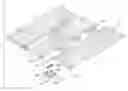
BRIEF DESCRIPTION OF THE DRAWINGSFIG. 1 is a perspective view of floor plates of the present invention;
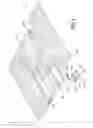
FIG. 2 is a schematic cross sectional view showing engagement between two adjacent floor plates;
FIG. 3 is a perspective view showing the completion of the engagement between adjacent floor plates; and
FIG. 4 is an exploded perspective view of the engagement between conventional floor plates.
DETAILED DESCRIPTION OF THE PREFERRED EMBODIMENTWith reference to FIGS. 1 and 2, it is noted that the floor plate (10) constructed in accordance with the present invention includes a first connection part (11) formed on a first side face of the floor plate (10) and a second connection part (12) formed on a second side face of the floor plate (10) opposite to the first connection part (11).
The first connection part (11) has a tongue (112) extending from the first side face, an upper cutout (110) defined in a top face of the tongue (112) and a lower cutout (111) defined in a bottom face of the tongue (112). A recess (113) is further defined in a face defining the lower cutout (111) to communicate with the lower cutout (111). The second connection part (12) is defined with a receiving space (120) defined in the second side face of the floor plate (10) to correspond to the tongue (112), a first slit (121) defined in a side face defining the receiving space (120) and a second slit (122) defined in the side defining the receiving space (120). Both the first slit (121) and the second slit (122) communicate with the receiving space (120).
A securing device (20) includes a base (21) with a wall (22) formed on a peripheral edge of a top face of the base (21) to be received in the lower cutout (111) and the recess (113) of the first connection part (11) of an adjacent floor plate (10) and a substantially L-shaped baffle (23) formed on a mediate portion of the top face of the base (21) to be received in the receiving space (120) and the first slit (121) of the second connection part (12). A side face opposite to and far away from the wall (22) of the base (21) corresponds to and is received in the second slit (122) of the second connection part (12).
Therefore, after applying securing elements (24) such as nails extending through the base (21) and into a first extension (123) between the first slit (121) and the second slit (122) and the tongue (112) from adjacent floor plate (10) is received in the receiving space (120) with a second extension (124) on top of the first extension (123) of the second connection part (12) received in the upper cutout (110) and the wall (22) received in the lower cutout (111) and the recess (113) of the first connection part (11) of the adjacent floor plate (10), two floor plates are combined. It is to be noted that after the securing device (20) is received in the receiving space (120), the space defined among the wall (22), the baffle (23) and the second extension (124) is not big enough to allow the tongue (112) to be inserted directly. Thus the tongue (112) from adjacent floor plate (10) is first oblique to the base (21) to allow the tongue (112) to have access to the space defined among the wall (22), the baffle (23) and the second extension (124). Then the tongue (112) is inserted into the receiving space (120) limited by the securing device (20).
Furthermore, a spacer (25) made of rubber or Ethylene Vinyl Acetate (EVA) is inserted in a space between the wall (22) and the baffle (23) such that once the tongue (112) is inserted into the receiving space (120) of the second connection part (12) after the baffle (23) is first received in the receiving space (120), the spacer (25) is able to properly space apart two adjacent floor plates (10) when the two adjacent floor plates (10) are deforming due to temperature or humidity change.
It is to be understood, however, that even though numerous characteristics and advantages of the present invention have been set forth in the foregoing description, together with details of the structure and function of the invention, the disclosure is illustrative only, and changes may be made in detail, especially in matters of shape, size, and arrangement of parts within the principles of the invention to the full extent indicated by the broad general meaning of the terms in which the appended claims are expressed.
Claims
What is claimed is:1. A combinable floor plate comprising:
a first connection part formed on a first side face of the floor plate and having a tongue extending from the first side face, an upper cutout defined in a top face of the tongue, a lower cutout defined in a bottom face of the tongue and a recess defined in a bottom face defining the lower cutout to communicate with the lower cutout;
a second connection part formed on a second side face of the floor plate opposite to the first connection part, the second connection part having a receiving space defined in the second side face of the floor plate to correspond to the tongue, a first slit defined in a side face defining the receiving space to communicate with the receiving space and a second slit defined in the side defining the receiving space to communicate with the receiving space; and
a securing device including a base with a wall formed on a top face of the base to be received in the lower cutout and the recess of the first connection part of an adjacent floor plate and a substantially L-shaped baffle formed on a mediate portion of the top face of the base to be received in the receiving space and the first slit of the second connection part, wherein a side face opposite to and far away from the wall is received in the second slit of the second connection part, such that after securing elements are applied to extend through the base and into a first extension formed on the second side face of the floor plate between the first slit and the second slit and the tongue from adjacent floor plate is received in the receiving space with a second extension formed on top of the first extension of the second connection part received in the upper cutout and the wall received in the lower cutout and the recess of the first connection part of the adjacent floor plate, two floor plates are combined.
2. The combinable floor plate as claimed in claim 1, wherein a spacer is inserted into the receiving space to adjust distance between two adjacent and joined floor plates.
3. The combinable floor plate as claimed in claim 2, wherein the spacer is made of rubber.
4. The combinable floor plate as claimed in claim 2, wherein the spacer is made of ethylene vinyl acetate.
Images & Drawings included:


Sources:
- United States Patent and Trademark Office - verify current appl. status at the USPTO↗
Similar patent applications:
- » 20070151189
Securing device for combining floor plates
Recent applications in this class:
- » 20250163707 2025-05-22
Deck Board End Cap Device - » 20250092688 2025-03-20
MECHANICAL LOCKING OF FLOOR PANELS WITH VERTICAL SNAP FOLDING - » 20240376721 2024-11-14
SYSTEM AND METHOD FOR FITTING FLOOR MODULES - » 20240360680 2024-10-31
METHOD FOR COMPOSING A SET OF FLOOR PANELS - » 20230383544 2023-11-30
PERIODIC AND NONPERIODIC TILING SYSTEM BASED ON REGULAR HEXAGONS - » 20230243158 2023-08-03
Tie-down anchor - » 20230203822 2023-06-29
Interlocking tile - » 20230124128 2023-04-20
PANEL CONNECTION - » 20210207384 2021-07-08
Method for composing a set of floor panels - » 20200063440 2020-02-27
SMART FLOOR TILES AND SMART FLOOR SYSTEMS