Cord control device for Roman shade
US20060196611A1
2006-09-07
11/068,771
2005-03-02
Abstract:
A cord control device for a window covering includes a frame mounted in a housing for the window covering. The cord control device further includes a roller having a first roller half and a second roller half that is rotatably supported by the frame and that is releasably engaged with the first roller half. At least one of the first roller half and the second roller half includes a cord hole, allowing an end of a cord to extend through a cord hole of the frame and the cord hole of the roller. The end of the cord is tied up to an outer side of the roller, and another end of the cord is attached to a shade body of the window covering, such that the roller and the cord turn jointly in a retracting direction or a releasing direction for retracting or releasing the shade body.
Interested in similar patents?
Get notified when new applications in this technology area are published.
Classification:
E06B9/262 » CPC main
Screening or protective devices for wall or similar openings, with or without operating or securing mechanisms; Closures of similar construction; Screens or other constructions affording protection against light, especially against sunshine; Similar screens for privacy or appearance; Slat blinds; Lamellar or like blinds, e.g. venetian blinds with flexibly-interconnected horizontal or vertical strips; Concertina blinds, i.e. upwardly folding flexible screens
E06B2009/2622 » CPC further
Screening or protective devices for wall or similar openings, with or without operating or securing mechanisms; Closures of similar construction; Screens or other constructions affording protection against light, especially against sunshine; Similar screens for privacy or appearance; Slat blinds; Lamellar or like blinds, e.g. venetian blinds with flexibly-interconnected horizontal or vertical strips; Concertina blinds, i.e. upwardly folding flexible screens Gathered vertically; Roman, Austrian or festoon blinds
A47H5/00 IPC
Devices for drawing draperies, curtains, or the like
Description
BACKGROUND OF THE INVENTION1. Field of the Invention
The present invention relates to a cord control device for a shade. In particular, the present invention relates to a cord control device for a Roman shade.
2. Description of the Related Art
Window coverings are used for shielding from sunlight and for privacy as well as decoration. FIG. 1 of the drawings illustrates a conventional Roman shade comprising a shade body (not shown) with a plurality of rings or loops (not shown) attached to a rear side thereof and a top assembly 1 that includes a housing 10 and a cord control device 11 for moving the shade body out of the housing 10 or into the housing 10 when not in use. The cord control device 11 comprises a frame 111 fixed in the housing 10, a roller 112 rotatably supported by the frame 111, and a spindle 117 extending through the roller 112 to turn therewith. A control member 116 is attached to an end of the housing 10 for sealing the housing 10. A pull string 118 is mounted to the control member 116 and operably connected to the spindle 117 such that the spindle 117 and the roller 112 rotate when the pull string 118 is pulled. A cord (not shown) is extended through the loops of the shade body. Further, the cord is extended through a cord hole 113 in the frame 111 and wound around the roller 112, with an end of the cord being tied up to a notch 114 in the roller 112. An end of the roller 112 is sealed by an end cap 115 to prevent disengagement of the knotted end of the cord. Thus, the shade body is coiled into or out of the housing 10 when the pull string 118 is pulled in a retracting direction or a releasing direction.
However, an end cap 115 is required for positioning the knotted end of the cord, resulting in an increase in the time and cost. Further, the end cap 115 has to be detached and then attached to the end of the roller 112 while mounting the cord. Further, before the last step of tying the end of the cord up to the notch 114 of the roller 112, the end of the cord has to be held by the installer, which is inconvenient.
SUMMARY OF THE INVENTIONAn objective of the present invention is to provide a cord control device that allows easy mounting of the cord while cutting the cost.
A cord control device for a window covering in accordance with the present invention comprises a frame mounted in a housing for the window covering. The cord control device further comprises a roller including a first roller half and a second roller half. The second roller half is rotatably supported by the frame. The first roller half is releasably engaged with the second roller half.
At least one of the first roller half and the second roller half includes a cord hole, allowing an end of a cord to extend through a cord hole of the frame and the cord hole of the at least one of the first roller half and the second roller half. The end of the cord is tied up to an outer side of the roller, and another end of the cord is attached to a shade body of the window covering, such that the roller and the cord turn jointly in a retracting direction or a releasing direction for retracting or releasing the shade body.
Preferably, at least one of the first roller half and the second roller half includes at least one rib on an inner side thereof to reinforce the structure of the roller.
Preferably, one of the first roller half and the second roller half includes at least one mortise, and the other of the first roller half and the second roller half includes at least one tenon for releasably engaging with the at least one mortise.
Other objectives, advantages, and novel features of the invention will become more apparent from the following detailed description when taken in conjunction with the accompanying drawings.
BRIEF DESCRIPTION OF THE DRAWINGSFIG. 1 is an exploded perspective view of a Roman shade with a conventional cord control device.
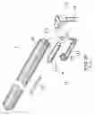
FIG. 2 is a perspective view of a cord control device for a Roman shade in accordance with the present invention.
FIG. 3 is an exploded perspective view of the cord control device for a Roman shade in accordance with the present invention.
FIG. 3A is an enlarged view of a circled portion in FIG. 3.
FIG. 4 is a sectional view taken along plane A-A in FIG. 2.
FIG. 5 is an exploded perspective view of a top assembly of a Roman shade and the cord control device in accordance with the present invention, wherein the shade body of the Roman shade is removed for clarity.
FIG. 6 is a perspective view of the Roman shade.
DETAILED DESCRIPTION OF THE PREFERRED EMBODIMENTReferring to FIGS. 5 and 6, a Roman shade comprises a shade body 23 with a plurality of rings or loops (not shown) attached to a rear side thereof and a top assembly 3 including a housing 30 and a cord control device 2 for moving the shade body 23 out of the housing 30 or into the housing 30 when not in use.
Referring to FIGS. 2 through 4, the cord control device 2 comprises a frame 21 fixed in the housing 30, a roller 22 rotatably supported by the frame 21, and a spindle 229 extending through the roller 22 to turn therewith. A control member 24 is attached to an end of the housing 30 for sealing the housing 30. A pull string 240 is mounted to the control member 24 and operably connected to the spindle 229 such that the spindle 229 and the roller 22 rotate when the pull string 240 is pulled.
The frame 21 includes a cord hole 211. The frame 21 further includes two ends 212 that are configured to rotatably support the roller 22. The roller 22 includes a first roller half 223 and a second roller half 224 that are assembled to form a substantially tubular structure. In the illustrated embodiment, the second roller half 224 includes a hollow axle 222 on each of two ends thereof, with each hollow axle 222 being rotatably supported by an associated end 212 of the frame 21. Each end of the second roller half 224 further includes a mortise 226. The first roller half 223 has a tenon 221 (FIG. 3A) on each of two ends thereof. Each tenon 221 of the first roller half 223 is releasably engaged with an associated mortise 226 of the second roller half 224. Thus, the first roller half 223 can be easily mounted to or detached from the second roller half 224.
The spindle 229 is extended through the hollow axles 222 and the roller 22 after assembly, allowing joint rotation of the spindle 229 and the roller 22.
At least one of the first roller half 223 and the second roller half 224 includes a cord hole 225. In the illustrated embodiment, a cord hole 225 is defined in each of the first roller half 223 and the second roller half 224.
A first end of a cord 4 is fixed to a bottom of a rear side of the shade body 23 and extends through the loops attached to the rear side of the shade body 23. Alternatively, the first end of the cord 4 is knotted below the lowermost loop of the shade body 23 so that the shape body 23 is pulled upward when the cord 4 is pulled upward, which is conventional.
A second end of the cord 4 is extended through the cord hole 211 of the frame 21. Then, the second end of the cord 4 is directly placed into, e.g., the second roller half 224 and then extended out of the second roller half 223 via the cord hole 225 of the second roller half 224. The second end of the cord 4 is knotted and thus tied up to the outer side of the second roller half 224, as shown in FIG. 4. The first roller half 223 is then coupled to the second roller half 224. A section of the cord is thus securely sandwiched between the first roller half 223 and the second roller half 224.
In an alternative arrangement, the second end of the cord 4 is extended out of the first roller half 223 via the cord hole 225 of the first roller half 223. The second end of the cord 4 is knotted and thus tied up to the outer side of the first roller half 223. The first roller half 223 is then coupled to the second roller half 224.
Thus, the cord 4 is coiled around or released from the roller 22 when the roller 22 is turned. As a result, the shade body 23 is coiled into or released out of the housing 23 when the pull string 240 is pulled in a retracting direction or a releasing direction.
Since the cord 4 for moving the shade body 23 is fixed to the roller 22 by the roller 22 consisting of two roller halves 223 and 224, no end cap is required for preventing disengagement of the cord 4. The mold for producing the end cap and the troublesome assembling procedure of the end cap are not required. The cost is thus significantly cut. Further, mounting of the cord 4 can be easily achieved, as the first roller half 223 can be easily detached from the second roller half 224 for mounting the cord 4, and the first roller half 223 can be easily attached to the second roller half 224 after mounting of the cord 4.
At least one rib 227 is formed on an inner side of at least one of the first roller half 223 and the second roller half 224. In the illustrated embodiment, two ribs 227 are formed on the inner side of each of the first roller half 223 and the second roller half 224. The ribs 227 improve the strength of the roller 22 without interfering with mounting of the spindle 229 and the cord 4.
Although the embodiment of the invention is illustrated and described with reference to a Roman shade, it is appreciated that the cord control device can be used with window coverings of other types.
Although a specific embodiment has been illustrated and described, numerous modifications and variations are still possible without departing from the essence of the invention. The scope of the invention is limited by the accompanying claims.
Claims
What is claimed is:1. A cord control device for a window covering, the cord control device comprising:
a frame adapted to be mounted in a housing for the window covering, the frame including a cord hole; and
a roller including a first roller half and a second roller half, the second roller half being rotatably supported by the frame, the first roller half being releasably engaged with the second roller half;
at least one of the first roller half and the second roller half including a cord hole, allowing an end of a cord to extend through the cord hole of the frame and the cord hole of said at least one of the first roller half and the second roller half, with the end of the cord being tied up to an outer side of the roller, and with another end of the cord being attached to a shade body of the window covering, such that the roller and the cord turn jointly in a retracting direction or a releasing direction for retracting or releasing the shade body.
2. The cord control device for a window covering as claimed in claim 1, wherein at least one of the first roller half and the second roller half includes at least one rib on an inner side thereof.
3. The cord control device for a window covering as claimed in claim 1, wherein one of the first roller half and the second roller half includes at least one mortise, and wherein the other of the first roller half and the second roller half includes at least one tenon for releasably engaging with said at least one mortise.
Images & Drawings included:


Sources:
- United States Patent and Trademark Office - verify current appl. status at the USPTO↗
Recent applications in this class:
- » 20250109631 2025-04-03
SHADE MEMBER AND WINDOW BLIND HAVING SAME - » 20250052109 2025-02-13
AN ARRANGEMENT FOR AT LEAST PARTIALLY COVERING A WINDOW - » 20250003287 2025-01-02
WINDOW SHADE AND PANEL ASSEMBLY THEREOF - » 20240401403 2024-12-05
HIDDEN COVERING FOR TWO PANEL FENESTRATION UNIT - » 20240337150 2024-10-10
METHOD AND STRUCTURE FOR FORMING A HONEYCOMB CURTAIN - » 20240279984 2024-08-22
INTEGRATED PLEATED SCREEN ASSEMBLY - » 20240218732 2024-07-04
ADHESIVE JOINT BETWEEN WOVEN AND NONWOVEN FABRIC FOR A CELLULAR SHADE - » 20240151101 2024-05-09
ROMAN BLIND WITH SHROUD PROTECTION - » 20240076933 2024-03-07
SHADE CONFIGURED TO BE CHANGED IN WIDTH AND HEIGHT AND CONFIGURED TO TRANSFORM BETWEEN DIFFERENT TYPES OF SHADES - » 20230417103 2023-12-28
Blind, a glazing system for a terrace or a balcony, and a method for arranging a blind in connection with a glazing system for a terrace or a balcony