Servo control apparatus
US20060198068A1
2006-09-07
11/338,787
2006-01-25
✅ Patent granted
US 7,279,861 B2
2007-10-09
-
-
Paul Ip
2026-02-24
Abstract:
In a servo control apparatus constituted by a converter unit 3 for rectifying an AC power supply voltage to produce a DC power supply voltage, and a plurality of inverter units 5 for producing drive power supply voltages of motors from the DC power supply voltage, the servo control apparatus is provided with a power supply breaker 2 which is connected to the side of the AC power supply of the converter unit 3; and a ground fault detecting circuit 16 built in the converter unit 3. When a ground fault happens to occur, the servo control apparatus stops the operations of all of the inverter units 5 so as to cut off the breaker 2.
Assignee:
- Kabushiki Kaisha Yasakawa Denki 9 🇯🇵 Fukuoka, Japan
Interested in similar patents?
Get notified when new applications in this technology area are published.
Classification:
H02H7/1216 » CPC main
Emergency protective circuit arrangements specially adapted for specific types of electric machines or apparatus or for sectionalised protection of cable or line systems, and effecting automatic switching in the event of an undesired change from normal working conditions for converters; for rectifiers for static converters or rectifiers for AC-AC converters
H02H1/0038 » CPC further
Details of emergency protective circuit arrangements concerning the connection of the detecting means, e.g. for reducing their number
H02H9/08 IPC
Emergency protective circuit arrangements for limiting excess current or voltage without disconnection Limitation or suppression of earth fault currents, e.g. Petersen coil
H02P5/74 IPC
Arrangements specially adapted for regulating or controlling the speed or torque of two or more electric motors controlling two or more ac dynamo-electric motors
H02P3/18 IPC
Arrangements for stopping or slowing electric motors, generators, or dynamo-electric converters for stopping or slowing an individual dynamo-electric motor or dynamo-electric converter for stopping or slowing an ac motor
H02P27/06 IPC
Arrangements or methods for the control of AC motors characterised by the kind of supply voltage using variable-frequency supply voltage, e.g. inverter or converter supply voltage using dc to ac converters or inverters
Description
BACKGROUND OF THE INVENTIONThe present invention is related to a servo control apparatus which is constituted in a multiple shaft manner by a converter unit and a plurality of inverter units.
As conventional techniques for detecting ground faults, for example, a patent publication 1 is opened. The conventional techniques will now be explained with reference to drawings. FIG. 2 is a block diagram for showing an arrangement of one conventional technique. In FIG. 2, reference numeral 101 indicates an AC power supply which is grounded, and reference numeral 102 shows an AC/DC converting circuit (rectifying circuit and converter) which is arranged by a diode bridge and a smoothing capacitor CB. Reference numeral 103 indicates a DC/AC converting circuit (inverter) in which a bridge circuit is arranged by employing respective arms (namely, in U phase, V phase, W phase, X phase, Y phase, and Z phase) of transistors and diodes. The DC/AC converting circuit 103 outputs 3-phase AC power having an output frequency and an output voltage in correspondence with a frequency command. The output of the DC/AC converting circuit 103 is connected to an induction motor 104, so that the induction motor 104 is driven in a variable speed. A load current of the Z phase of this induction motor 104 is detected by a current detector 105, and then, an output signal of the current detector 105 constitutes a signal “i” which is directly in proportional to the load current. This current “i” is continuously compared with each other by an overcurrent detectingcircuit106 so as to perform an overcurrent protection. That is, in the overcurrent protection, when the overcurrent is detected by the overcurrent detecting circuit 106, the operation of the DC/AC converting circuit 103 is stopped. Further, the current “i” is inputted to a comparator 111 of a ground fault detecting circuit 109. In the comparator 111, the signal “i” is compared with a reference value vs2, and when the signal “i” exceeds the reference value vs2, the comparator 111 outputs such a signal of an output “1.” A drive control circuit 108 outputs a signal “b” to a base drive circuit 107 during a normal operation. This signal “b” turns ON/OFF the transistors of the respective arms as to the U, V, W, X, Y, and Z phases. When the above-explained signal “b” is not outputted, the drive control circuit 108 further outputs aground fault detecting instruction signal “a” in response to a necessity of investigating a ground fault condition. When the signal “a” is inputted to a ground fault detecting-purpose base driving circuit 110, this ground fault detecting-purpose base driving circuit 110 outputs a drive signal with respect to the transistor of the Z phase for a predetermined time period. At this time, when a ground fault happens to occur in the output, as indicated in FIG. 2, a ground fault current “IG” flows through the transistor of the Z phase. At this time, the current detector 105 apparently detects a current “iG” of the Z phase to produce a signal “i.” The comparator 111 compares this signal “i” with the reference value vs2, and outputs a signal “c” of an output “1” when this signal “i” exceeds the reference value vs2. The signal “a” is entered to one input terminal of an AND circuit 113, and the above-explained signal “c” is entered from the comparator 111 to the other input terminal of the AND circuit 13. When both the signal “a” and the signal “c” are “1”, the AND circuit 113 outputs a signal “d” of an output “1.” The output signal “d” of the AND circuit 113 is inputted to a latch circuit 114 so as to be latched by the latch circuit 114. An output signal “g” of this latch circuit 114 prohibits the operation of the base drive circuit 107, and furthermore, is outputted to a display device 112, so that the display device 112 displays an occurrence of the ground fault and produces an alarm. Also, in addition, this output signal “g” of the latch circuit 114 is outputted as a ground fault detection signal to an external unit.
Also, another conventional technique is shown in FIG. 3. FIG. 3 is such an example that a servo control apparatus of multiple shafts such as a robot is constructed. In an application example to a robot, motors are built in the robot, and the servo control apparatus is connected to a robot control apparatus. Wiring lines wired to the motors are penetrated through the robot, and are moved in response to operations of the robot. originally, cables having anti-bending characteristics are used as these wiring lines. However, in connection with such a fact that action ranges of the robot are expanded, the bending ratio of the cables is increased. As a result, there is such an actual fact that occurring ratios of mechanical wearing of the cables and of disconnections of the cables become very high, as compared with those of other systems. In robot systems, ground fault detecting functions are necessary required. In FIG. 3, reference numeral 1 shows a power supply, reference numeral 2 indicates a breaker, reference numeral 3 represents a converter unit, reference numeral 4 shows a servo control circuit, and reference numeral 5 shows an inverter unit. Also, reference numeral 6 denotes a ground fault detecting circuit, reference numeral 7 shows a current detector, and reference numeral 8 denotes a motor. Since the current detector 7 is inserted in the output of the inverter unit 5, a zero-phase-sequence current is detected. As a method of detecting a zero-phase-sequence current, a sum of currents which flow through wired lines is detected. If no ground fault occurs, then the sum of currents becomes zero. When the ground fault is detected by the ground fault detecting circuit 6, the ground fault detecting circuit 6 outputs a ground fault signal to the servo-control circuit 4, and thus, the servo control circuit 4 is designed to turn OFF a power element of the inverter unit 5 and the breaker 2.
[Patent Document 1]
JP-A-5-328739 (FIG. 1)
However, in the conventional technique, since the zero-phase-sequence current detectors are used in the outputs of the inverter unit, plural sets of these zero-phase-sequence detectors and plural sets of ground fault current detecting circuits are required, the total quantities of which are equal to a total number of the shafts. Also, in order to turn OFF the breaker, the ground fault signals derived from the respective shafts must be received. As a result, plural sets of the wiring lines are required for the total quantity of these shafts. Among current servo control systems for robots, in particular, a strong demand as to compact sizes is made, and volumes occupied by servo control apparatus may become a problem and higher cost is required.
SUMMARY OF THE INVENTIONThe present invention is made to solve such a problem, and therefore, has an object to provide a servo control apparatus equipped with a ground fault detecting function, and manufactured in a compact size and in low cost.
To solve the above-explained problem, a servo control apparatus of the present invention is arranged as follows:
According to the aspect 1, there is provided with a servo control apparatus including: a converter unit for rectifying an AC power supply voltage to produce a DC power supply voltage, a plurality of inverter units for producing driving power supply voltages of servo motors from the DC power supply voltage, and for driving the servo motors which are mutually coupled to each other, a breaker connected to the AC power supply side of the converter unit, and a ground fault detecting circuit built in the converter unit, wherein when the ground fault detecting circuit detects a ground fault, the servo control apparatus stops operations of all of the inverter units and cuts off the breaker.
According to the aspect 2, there is provided with the servo control apparatus as in the aspect 1, wherein the ground fault detecting circuit is connected on the side of the AC power supply of the converter unit.
According to the aspect 3, there is provided with the servo control apparatus as in the aspect 1, wherein the ground fault detecting circuit is connected on the side of the DC power supply of the converter unit.
According to the aspect 4, there is provided with the servo control apparatus as in the aspect 1, wherein the breaker is a contactor.
According to the aspect 5, there is provided with the servo control apparatus as in the aspect 1, wherein the ground fault detecting circuit is a zero-phase-sequence current detector.
In accordance with the present invention, the compact servo control apparatus equipped with the ground fault detecting function and manufactured in low cost can be provided.
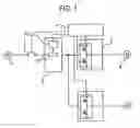
BRIEF DESCRIPTION OF THE DRAWINGSFIG. 1 is a block diagram for indicating an arrangement of a servo control apparatus of the present invention.
FIG. 2 is a block diagram for showing the arrangement of the inverter having the conventional ground fault protection function.
FIG. 3 is a block diagram for showing the arrangement of the multi-shaft servo control apparatus having the conventional ground fault protection function.
FIG. 4 is a block diagram for indicating a first embodiment of the present invention.
FIG. 5 is a block diagram for indicating a second embodiment of the present invention.
DETAILED DESCRIPTION OF THE PREFERRED EMBODIMENTSReferring now to drawings, various embodiments of the present invention will be described in detail.
FIG. 1 is a block diagram for showing a robot-purpose servo control apparatus of the present invention. In this drawing, reference numeral 1 shows a power supply, reference numeral 2 indicates a breaker, reference numeral 3 represents a converter unit, reference numeral 4 shows a servo control circuit, and reference numeral 5 shows an inverter unit. Also, reference numeral 8 denotes a motor, and reference numeral 16 represents a ground fault detecting circuit. Only one set of the ground fault detecting circuit 16 is employed irrespective of a total shaft number of motors. In the case of a general-purpose servo system, a merit obtained by detecting a problem with respect to each of plural shafts is given as follows: That is, since only such a servo that a problem has occurred is cut off and other motors are driven, the entire servo system may be operated in some cases. However, in the case of a robot system, and the like, respective shafts of the robot system are mutually coupled to each other. As a result, there is no merit if only one shaft is stopped, conversely speaking, there is a risk when only one shaft is stopped. As a consequence, when the ground fault detecting circuit 16 detects a ground fault in the robot-purpose servo control apparatus, bases of major circuit transistors employed in all of the inverter units 5 are electrically blocked so as to stop the inverting operations of these inverter circuits 5, and thus, the servo control apparatus is cut off from the AC power supply by the breaker 2.
Embodiment 1FIG. 4 is an example in which a zero-phase-sequence current detector is provided on the side of a DC power supply of a converter. A merit obtained by providing such a zero-phase-sequence current detector on the side of the DC power supply is given as follows: That is, in the case that a zero-phase-sequence current transformer is employed as the zero-phase-sequence current detector, two lines of a plus side and a minus side are linked irrespective of a total number of phases. As a result, the zero-phase-sequence current transformer can be made compact, and a total number of wiring lines can be reduced.
Embodiment 2FIG. 5 is an example in which a zero-phase-sequence current detector is provided on the side of an AC power supply of a converter unit. A merit achieved by providing such a zero-phase-sequence current detector on the side of the AC power supply is given as follows: That is, a range of circuit portions to be detected becomes wide. For example, in the case that the zero-phase-sequence current detector is provided on the side of the DC current power supply, when a ground fault happens to occur in a rectifying diode of the converter unit, this ground fault cannot be detected. However, generally speaking, there is a rare case that a ground fault happens to occur in a stationary unit, and therefore, even when the ground fault detecting circuit is provided on any side of the AC power supply and the DC power supply, there is no large difference.
Since the servo control apparatus of the present invention can have the ground fault detecting function and can be realized in the compact size and the low cost, it is possible to expect that the servo control apparatus may be applied not only to robots, but also to general-purpose industrial machines which use motors having multiple shafts.
Claims
What is claimed is :1. A servo control apparatus comprising:
a converter unit for rectifying an AC power supply voltage to produce a DC power supply voltage,
a plurality of inverter units for producing driving power supply voltages of servomotors from the DC power supply voltage, and for driving the servo motors which are mutually coupled to each other,
a breaker connected to the AC power supply side of the converter unit, and
a ground fault detecting circuit built in the converter unit, wherein
when the ground fault detecting circuit detects a ground fault, the servo control apparatus stops operations of all of the inverter units and cuts off the breaker.
2. The servo control apparatus as claimed in claim 1, wherein the ground fault detecting circuit is connected on the side of the AC power supply of the converter unit.
3. The servo control apparatus as claimed in claim 1, wherein the ground fault detecting circuit is connected on the side of the DC power supply of the converter unit.
4. The servo control apparatus as claimed in claim 1, wherein the breaker is a contactor.
5. The servo control apparatus as claimed in claim 1, wherein the ground fault detecting circuit is a zero-phase-sequence current detector.
Images & Drawings included:


Sources:
- United States Patent and Trademark Office - verify current appl. status at the USPTO↗
Similar patent applications:
- » 20180373223
Machine learning apparatus, servo control apparatus, servo control system, and machine learning method - » 20070286033
Servo control apparatus, servo control method, optical disc apparatus and video camera recorder - » 20170315513
Servo control apparatus, servo control method, and non-transitory computer-readable medium, with filter added to proportional term calculated at high speed - » 20180284703
Machine learning device, servo control apparatus, servo control system, and machine learning method - » 20170277206
Servo control apparatus, servo control method and computer-readable recording medium - » 20230324884
SERVO CONTROL APPARATUS AND SERVO CONTROL METHOD - » 20080297819
SERVO CONTROL APPARATUS IN OPTICAL DISC DEVICE AND METHOD OF CONTROLLING SERVO - » 20150042256
Servo apparatus, and controlling method of servo apparatus - » 20050004686
Servo control apparatus control method - » 20080054834
Servo control apparatus
Recent applications in this class:
- » 20210376594 2021-12-02
Resistive sub-module hybrid MMC and direct current fault processing strategy thereof - » 20200136370 2020-04-30
Protection coordination technique for power converters - » 20190312425 2019-10-10
Power converter with ground fault detection function and fault detection method - » 20190214811 2019-07-11
Power conversion apparatus - » 20180366942 2018-12-20
Bipole voltage source converter and control and operation thereof - » 20180145503 2018-05-24
Overcurrent protection device for semiconductor device - » 20180097353 2018-04-05
Differential fault detection system - » 20160087426 2016-03-24
Power source switching device and storage battery system - » 20150372481 2015-12-24
System and method for protecting a power converter during an adverse voltage event - » 20140192570 2014-07-10
Isolating faulty converter module in converter system with interconnected DC links
Recent applications for this Assignee:
- » 20070170885 2007-07-26
Motor control apparatus and method for generating modulation wave instruction of PWM inverter of the same motor control apparatus - » 20060119105 2006-06-08
Power generating system and its control method - » 20060087275 2006-04-27
Gain adjusting method for servo control device - » 20050280315 2005-12-22
Tandem arrangement linear motor - » 20050206246 2005-09-22
Voice coil-type linear motor with cooling function - » 20050140213 2005-06-30
Linear motor armature and linear motor - » 20050122242 2005-06-09
Absolute encoder and absolute value signal generation method - » 10781911 2007-10-30
Arc welder