Dehumidifying device
US20060201162A1
2006-09-14
11/077,618
2005-03-11
Abstract:
A dehumidifying device has a hollow body. An air inlet and an air outlet are respectively defined in two opposed sides of the body. A heat exchanger and a blower are provided in an airflow passage which is formed between the air inlet and the air outlet. A water passage is provided under the heat exchanger and a reservoir is provided under the water passage so that water which is condensed by the present invention can be purified for drinking etc.
Interested in similar patents?
Get notified when new applications in this technology area are published.
Classification:
C02F1/18 » CPC main
Treatment of water, waste water, or sewage by heating by distillation or evaporation Transportable devices to obtain potable water
B01D5/009 » CPC further
Condensation of vapours; Recovering volatile solvents by condensation characterised by auxiliary systems or arrangements Collecting, removing and/or treatment of the condensate
B01D53/265 » CPC further
Separation of gases or vapours; Recovering vapours of volatile solvents from gases; Chemical or biological purification of waste gases, e.g. engine exhaust gases, smoke, fumes, flue gases, aerosols,; Drying gases or vapours by refrigeration (condensation)
C02F1/283 » CPC further
Treatment of water, waste water, or sewage by sorption using coal, charred products, or inorganic mixtures containing them
C02F1/32 » CPC further
Treatment of water, waste water, or sewage by irradiation with ultra-violet light
C02F1/441 » CPC further
Treatment of water, waste water, or sewage by dialysis, osmosis or reverse osmosis by reverse osmosis
C02F2201/009 » CPC further
Apparatus for treatment of water, waste water or sewage Apparatus with independent power supply, e.g. solar cells, windpower, fuel cells
Y02A20/00 » CPC further
Water conservation; Efficient water supply; Efficient water use
Y02A20/211 » CPC further
Water conservation; Efficient water supply; Efficient water use; Controlling water pollution; Waste water treatment; Off-grid powered water treatment Solar-powered water purification
Y02A20/212 » CPC further
Water conservation; Efficient water supply; Efficient water use; Controlling water pollution; Waste water treatment; Off-grid powered water treatment Solar-powered wastewater sewage treatment, e.g. spray evaporation
F25B21/02 IPC
Machines, plants or systems, using electric or magnetic effects using Peltier effect; using Nernst-Ettinghausen effect
F25D17/06 IPC
Arrangements for circulating cooling fluids; Arrangements for circulating gas, e.g. air, within refrigerated spaces for circulating air, e.g. by convection by forced circulation
F25D21/14 IPC
Defrosting; Preventing frosting; Removing condensed or defrost water Collecting or removing condensed and defrost water; Drip trays
Description
BACKGROUND OF THE INVENTION1. Field of the Invention
The present invention relates to a dehumidifying device, and more particularly to a dehumidifying device which has an effect of filtering water therein.
2. Description of Related Art
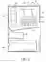
With reference to FIG. 4, a first conventional dehumidifying device (4), which can filter water derived from redundant moisture in the air, has a hollow body (40). An air inlet (41) and an air outlet (42) are respectively provided on two opposed sides of the conventional dehumidifying device (4). An airflow passage (not numbered), which is formed between the air inlet (41) and the air outlet (42), has a heat exchanger (43) and a blower (44) therein. The heat exchanger (43) is composed of a steamer (431) and a condenser (432), and a compressor (47) is provided in a lower end of the hollow body (40). A water passage (45) is provided under the airflow passage, and a reservoir (46) is mounted under the water passage (45).
When the first conventional dehumidifying device (4) is operating, a refrigerant circulates in the heat exchanger (43) due to the compressor (47) and the air enters the body (40) through the air inlet (41) due to the blower (44) so that the air with moisture can perform heat exchange through the steamer (431) and the condenser (432) and reduce the temperature of the air due to the refrigerant. Hence, the moisture of the air can be condensed to drops of water and gathered in the reservoir (46) via the water passage (45). The air, the humidity in which can be decreased due to the steamer (431) absorbing the heat and the condenser (432) exporting the heat, can be exhausted via the air outlet (42).
With reference to FIG. 5, another preferred embodiment of a second conventional dehumidifying device (5) comprises a hollow body (50). An air inlet (51) and an air outlet (52) are respectively provided on two sides of the body (50) and an airflow passage is formed between the air inlet (51) and the outlet (52). A heat exchanger (53), which comprises a radiator (531), a refrigeration means (532), and a condenser (533), and a blower (not numbered) are provided in the airflow passage. The radiator (531) is composed of heat sinking slats, and the refrigeration means (532) is composed of chilling chips. The heat exchanger (53), which can be controlled by a circuit board (not numbered), has a water passage (55) thereunder. A reservoir (56) is provided under an out port of the water passage (55). The dehumidifying device (5) is an electrical dehumidifying device, the heat exchanger (53) of which is controlled by the circuit board so that the moisture of the air can be condensed to drops of water thereby dripping into the water passage (55) and accumulating in the reservoir (56).
However, the collected water of the first and second conventional dehumidifying devices (4, 5) is not appropriate for people to drink or use because it may have impurities therein. Hence, the collected water is only used to irrigate plants, clean floors thereby not maximizing the water resource.
Therefore, the invention provides a dehumidifying device to mitigate or obviate the aforementioned problems.
SUMMARY OF THE INVENTIONThe main objective of the present invention is to provide a dehumidifying device, collected water in which can be drunk or used.
Other objectives, advantages and novel features of the invention will become more apparent from the following detailed description when taken in conjunction with the accompanying drawings.
BRIEF DESCRIPTION OF THE DRAWINGSFIG. 1 is a sectional view of a first preferred embodiment of a dehumidifying device of the present invention;
FIG. 2 is a sectional view of a second preferred embodiment of the dehumidifying device of the present invention;
FIG. 3 is a sectional view of the third preferred embodiment of the dehumidifying device of the present invention;
FIG. 4 is a sectional view of a first conventional dehumidifying device; and
FIG. 5 is a sectional view of a second conventional dehumidifying device.
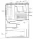
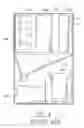
DETAILED DESCRIPTION OF THE PREFERRED EMBODIMENTWith reference to FIG. 1, a first preferred embodiment of a dehumidifying device (1) has a hollow body (10), and an air inlet (11) and an air outlet (12) are respectively defined in two sides of the hollow body (10). An airflow passage, which is formed between the air inlet (11) and the air outlet (12), is provided with a heat exchanger (13) and a blower (14). A compressor (18) is provided in a lower end of the hollow body (10) and a water passage (15) is provided under the heat exchanger (13). A reservoir (17) for gathering water is mounted under a water outlet of the water passage (15).
The heat exchanger (13) is composed of a steamer (131) and a condenser (132) which are both connected to the compressor (18) through a refrigeration tube thereby forming a circulation passage so that the temperature of the air can fall due to the heat exchanger (13) and the moisture in the air can be condensed to drops of water and be collected by the water passage (15).
A filter (16) is provided between the water outlet of the water passage (15) and the reservoir (17) so that the water which is collected by the water passage (15) can be filtered through the filter (16) and stored in the reservoir (17). Therefore, the water which is purified by the filter (16) can be drunk and used in many useful ways.
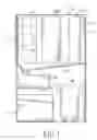
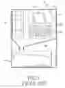
With reference to FIG. 2, a second preferred embodiment of the dehumidifying device (2) has a hollow body (20) with an air inlet (21) and an air outlet (22) respectively defined in two sides of the hollow body (20). An airflow passage, which is formed between the air inlet (21) and the air outlet (22), is provided with a heat exchanger (23) and a blower (24). The heat exchanger (23) includes a radiator (231), a refrigeration means (232) and a condenser (233). The heat exchanger (23) can be controlled by the circuit board and a water passage (25) is provided under the heat exchanger (23). A reservoir (26) is provided under a water outlet of the water passage (25). In the second preferred embodiment of the dehumidifying device (2), an electrical dehumidifying device turns the moisture of the air into water falls into the water passage (25) due to the circuit board controlling the heat exchanger (23).
A filter (30) is provided between the water outlet of the water passage (25) and the reservoir (26) so that the water which is collected by the water passage (25) can be filtered through the filter (30) and then stored in the reservoir (26). Therefore, the water which is purified by the filter (30) can be drunk and used in many useful ways.
The filter (16, 30) can purify the water with filtering layers of active carbon materials or with filtering layers of multiple filter beds, filter films and active carbon materials. Furthermore, with a theory of reverse osmosis, the filter (16, 30) comprises multiple reverse osmose films and a motor which can pump the water thereby forcing it through the converse infiltrating films and effective insulating mineral substance such as calcium, magnesium, potassium, aluminum, and heavy metals to soften the water. The filter (16, 30) can also include filtering layers with the active carbon materials and a filtering core which can exchange ions into resin. Additionally, the filter (16, 30) has filter layers with a filtering core with carbon ions which can filter impurities and germs, and can electrolyte the water into alkali ion water with the active carbon materials. Or, an ultraviolet radiation means can be provided on the filter (16, 30) to kill the germs in the water.
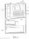
With reference to FIG. 3, a solar energy plate (27) is provided on a top end of the dehumidifying device (1, 2) thereby absorbing the solar energy so that the solar energy can be transformed to electrical energy to operate the blower (24) and save electricity.
It is to be understood, however, that even though numerous characteristics and advantages of the present invention have been set forth in the foregoing description, together with details of the structure and function of the invention, the disclosure is illustrative only, and changes may be made in detail, especially in matters of shape, size, and arrangement of parts within the principles of the invention to the full extent indicated by the broad general meaning of the terms in which the appended claims are expressed.
Claims
What is claimed is:1. A dehumidifying device (1, 2) comprising:
a hollow body (10, 20);
an air inlet (11, 21) and an air outlet (21, 22) respectively provided on two opposed sides of the hollow body (10, 20);
an airflow passage formed between the air inlet (11, 21) and the air outlet (12, 22);
a heat exchanger (13, 23) and a blower (14, 24) provided in the airflow passage;
a water passage (15, 25) provided under the heat exchanger (13, 23);
a reservoir (17, 26) mounted under the water passage (15, 25); and
a filter (16, 30) provided between a water outlet of the water passage (15, 25) and the reservoir (17, 26).
2. The dehumidifying device (1, 2) as claimed in claim 1, wherein a solar energy plate is provided on a top end of the hollow body (10, 20).
Images & Drawings included:
Sources:
- United States Patent and Trademark Office - verify current appl. status at the USPTO↗
Similar patent applications:
- » 20090015673
Monitoring camera device, dehumidifying device, dehumidifying method, and dehumidifying program - » 20200027665
Dehumidifying devices, and data storage devices having one or more dehumidifying devices - » 20150375171
Dehumidifying device and dehumidifying module - » 20220387972
Dehumidifying element, dehumidifying device including dehumidifying element, and method of manufacturing dehumidifying element - » 20230146349
Dehumidifying element, dehumidifying device, and a method of manufacturing dehumidifying element - » 20080047669
DEHUMIDIFYING DEVICE FOR DOUBLE-FACED CORRUGATED PAPERBOARD - » 20170363278
Dehumidifying device and lamp - » 20070040290
Fixed moisture siphon-infiltration type honeycomb dehumidifying device - » 20050217486
Dehumidifying device - » 20080054844
Dehumidifying device for rechargeable electronic equipment
Recent applications in this class:
- » 20230212034 2023-07-06
Method for obtaining clean drinking water from dewatered biological products and a device for dewatering such products - » 20230002248 2023-01-05
MOBILE WATER PURIFICATION SYSTEM - » 20210188663 2021-06-24
Apparatus, System and Method for Resource Distribution - » 20200002187 2020-01-02
Fluid transportation and filtering container - » 20190169045 2019-06-06
Apparatus, system and method for resource distribution - » 20170283277 2017-10-05
Solar thermal device for the treatment of drinking water - » 20170225966 2017-08-10
Portable Collapsible Distillation Apparatus and Methods - » 20170008777 2017-01-12
ADAPTER FOR CONNECTING AT LEAST TWO PLASTIC BOTTLES - » 20140116870 2014-05-01
Apparatus, system and method for resource distribution - » 20130213865 2013-08-22
Fresh water generator utilizing air