Electrical machine
US20060202585A1
2006-09-14
10/540,199
2003-12-08
✅ Patent granted
US 7,215,056 B2
2007-05-08
WO; PCT/DE03/04037; 20031208
WO; WO2004/057735; 20040708
Burton Mulllins
2023-12-17
Abstract:
In order to prevent, among other things, fatigue failures in squirrel-cage rotors of electrical machines, the invention provides that the squirrel-cage winding is comprised of flexible conductors.
Assignee:
- SIEMENS AKTIENGESELLSCHAFT 4,819 🇩🇪 Munchen, Germany
Interested in similar patents?
Get notified when new applications in this technology area are published.
Classification:
H02K17/165 » CPC main
Asynchronous induction motors; Asynchronous induction generators; Asynchronous induction motors having rotors with internally short-circuited windings, e.g. cage rotors characterised by the squirrel-cage or other short-circuited windings
H02K21/00 IPC
Synchronous motors having permanent magnets; Synchronous generators having permanent magnets
H02K17/16 IPC
Asynchronous induction motors; Asynchronous induction generators; Asynchronous induction motors having rotors with internally short-circuited windings, e.g. cage rotors
Description
The invention relates to an electric machine with a squirrel-cage rotor.
Asynchronous machines typically have rotors in form of a cage winding, whereby a respective rod is inserted in each of the slots, with the rods being connected at their respective end faces on the rotor by cage rings. Rods and cage rings are fabricated from aluminum or aluminum alloys by die casting, and have a higher resistance. However, copper, bronze or brass can also be used as electric conductors. The solid rods of the cage winding are typically inserted in the rotor without insulation and joined with the cage rings by soldering.
Disadvantageously, the cage rods have to be connected with the cage rings in a separate manufacturing step. Moreover, the projection of the rods at the end faces of the rotor does not contribute to torque generation. In addition, vibration fatigue frequently occurs due to the relatively rigid construction of the squirrel-cage, in particular at the solder joints.
It is therefore an object of the invention to provide a squirrel-cage for an electric machine, which obviates the aforementioned disadvantages.
The object is solved in that the squirrel-cage rotor has a cage winding made of flexible conductors, in particular stranded wires.
This eliminates vibration fatigue and shortens the projection of the conductors over the armature of the squirrel-cage rotor. The required short-circuit or cage connection is advantageously provided within the slots by electrically contacting, in particular, two electric conductors, in particular stranded conductors, placed in a slot in opposite directions. Electric contact is made, for example, by pressing.
The slots can be closed, semi-open or open. In particular with open slots, precautions have to be taken at least over certain sections for absorbing the centrifugal forces of the flexible conductors in the slot region.
Advantageously, the proximity effect can be reduced by implementing the electric conductors as flexible conductors, with a plurality of elements, which include individual bare wires that can be stranded or bunched. The cross-section of the stranded wire as well as of its filaments can have any imaginable geometric shapes, such as quadrilateral, rectangular, square, triangular or round.
The cross section over the length of a stranded wire or of a filament can be given different shapes by suitable processes.
The projection of the meandering conductors over the end faces of the squirrel-cage rotor according to the invention is relatively short. Because the electric conductors, in particular the stranded conductors, are flexible, holding elements are provided in one exemplary embodiment for absorbing the centrifugal forces during operation of the electric machine. These holding elements are made of a high-strength, electrically insulating material suitable for absorbing the centrifugal forces of the stranded conductors outside the armature. The holding elements are here implemented as a simple ring, but also as a trough-shaped, cap-like element, which at least partially encloses the projections. Advantageously, additional fan blades are provided on the holding element, which can either be attached separately on the holding element or be already, for example, cast during the manufacturing process.
The invention and additional advantageous implementations of the invention are shown in the illustrated exemplary embodiment. It is shown in:
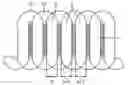
FIG. 1 schematically, a squirrel-cage rotor winding according to the invention, and
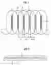
FIG. 2 a detail of the holding rings.
FIG. 1 shows, in an unrolled view, a squirrel-cage rotor with an armature 1 that includes several exemplary slots n, n+1, n+2, which are machined out of the armature 1. A conductor L2 is located in a lower layer of these slots and is wound in the opposite direction relative to a conductor L1 in an upper layer through the slots in a meander pattern. The conductors L1 and L2 are preferably stranded conductors consisting of individuals filaments. The stranded conductors are twisted with a predeterminable pitch.
The conductors L1 and L2 are electrically contacted preferably by pressing on the preferably bare stranded conductors in the slots n, n+1, n+2. The slot walls hereby provide the required back pressure. However, other types of electric contacts are possible, for example, by a conducting potting compound, which can be filled into the slots or into certain predeterminable axial slot regions, for example, after the conductors have been installed. This also fixes the stranded conductors in the slot.
The stranded conductors can also be electrically connected in these regions by melting them together.
In another embodiment, a mechanical contact can be provided by electrically conducting, mechanical elements which can be, for example, driven into these regions.
In yet another embodiment, at least sections of the stranded conductors located in a slot n, n+1, n+2 can be electrically connected by crimping. The stranded conductors are hereby pinched together or a conducting sheath surrounding the stranded conductors is pinched together at least in those regions to be contacted.
Advantageous, in particular with semi-open or closed slots n, n+1, n+2, the aforedescribed contacting operations can be performed in the regions 3, i.e., immediately after the conductors L1 and L2 exit from the armature 1.
The design of the squirrel-cage according to the invention also eliminates the conventional cage ring. This also eliminates the related installation steps, and prevents vibration fatigue. A cage connection can be provided by an electrically conducting connection from L1 to L2. L1 and L2 can also be alternatingly arranged in an upper and a lower layer, or the conductors L1 and L2 can be arranged side-by-side in a slot. The entire squirrel-cage rotor winding can also be constructed from more than 2 stranded conductors, so that a greater number of stranded conductors can be placed in one slot n, n+1, n+2.
FIG. 2 shows a detail of the front face of the armature 1. Since the projections of the squirrel-cage winding are now fabricated from stranded conductors, each of the conductors L1 and L2 is supported against centrifugal forces by a corresponding holding element, which is preferably implemented as a holding ring 2. In particular, the holding ring 2 is made of an electrically insulating material capable of absorbing the centrifugal forces. Pressed or pinched connections along sections can also be used to provide electric contact outside the armature 1 in the region of the holding ring 2.
The stranded conductors are mechanically fixed, with respect to one another and/or on the holding element 2, by adhesive joints and/or tie down elements.
According to another embodiment, the stranded conductors are no longer routed in parallel outside the armature 1. Each stranded conductors can then follow the shortest path to the next planned slot, whereby the next planned slot need not necessarily be the directly adjacent slot.
Claims
1.-4. (canceled)
5. An electric machine, comprising a squirrel-cage rotor having a cage winding made of flexible conductors, wherein the flexible conductors are stranded wires which are arranged in a meandering pattern, running in opposite directions, in slots of the squirrel-cage rotor, so as to establish a cage connection in the rotor.
6. The electric machine of claim 5, wherein the stranded wires are twisted with a predeterminable pitch.
7. The electric machine of claim 5, wherein the stranded wires have filaments, said stranded wires having different cross sectional configuration and their filaments having different cross sectional configuration.
8. The electric machine of claim 5, wherein the stranded wires have filaments, each of the stranded wires and its filaments have a length of different cross sectional configuration over a length thereof.
9. The electric machine of claim 5, wherein the cage winding of the squirrel-cage rotor includes more than two stranded wires.
10. The electric machine of claim 9, wherein the stranded wires are arranged in alternating pattern in an upper layer and lower layer of the slots.
11. The electric machine of claim 6, wherein the stranded wires in a slot are in electric contact.
12. The electric machine of claim 5, further comprising a holding element for keeping the stranded wires in position.
13. The electric machine of claim 12, wherein the holding element Is made of an electrically insulating material of high strength.
14. The electric machine of claim 12, wherein the holding element has a ring-shaped configuration.
15. The electric machine of claim 12, wherein the holding element has a trough-shaped, cap-like configuration.
16. The electric machine of claim 12, further comprising fan blades provided on the holding element.
17. The electric machine of claim 11, wherein the stranded wires are in electric contact through presetting in the slot.
18. The electric machine of claim 17, wherein the electric contact is realized at least in a section of the stranded wires.
19. The electric machine of claim 18, further comprising a conducting element driven into the section for establishing the electric contact between the stranded wires in the slot.
20. The electric machine of claim 17, wherein the electric contact is realized by a conducting potting compound filled in the slot.
21. The electric machine of claim 17, wherein the electric contact is realized immediately after the stranded wires exit the rotor.
Images & Drawings included:
Sources:
- United States Patent and Trademark Office - verify current appl. status at the USPTO↗
Similar patent applications:
- » 20240275219
STATOR CORE OF ROTATING ELECTRIC MACHINE, STATOR OF ROTATING ELECTRIC MACHINE, ROTATING ELECTRIC MACHINE, METHOD FOR MANUFACTURING STATOR CORE OF ROTATING ELECTRIC MACHINE, AND METHOD FOR MANUFACTURING ROTATING ELECTRIC MACHINE - » 20220344981
LAMINATED CORE OF ELECTRIC MACHINE, ELECTRIC MACHINE, METHOD FOR MANUFACTURING LAMINATED CORE OF ELECTRIC MACHINE, AND METHOD FOR MANUFACTURING ELECTRIC MACHINE - » 20220344980
STATOR FOR ROTATING ELECTRICAL MACHINE, ROTATING ELECTRICAL MACHINE, METHOD FOR MANUFACTURING STATOR FOR ROTATING ELECTRICAL MACHINE, AND METHOD FOR MANUFACTURING ROTATING ELECTRICAL MACHINE - » 20210328486
METHOD FOR MANUFACTURING UNIT COIL FOR STATOR OF ROTARY ELECTRIC MACHINE, DEVICE FOR MANUFACTURING UNIT COIL FOR STATOR OF ROTARY ELECTRIC MACHINE, ROTARY ELECTRIC MACHINE, AND METHOD FOR ROTARY ELECTRIC MACHINE - » 20240085480
INSPECTION DEVICE FOR ROTARY ELECTRIC MACHINE, INSPECTION SYSTEM FOR ROTARY ELECTRIC MACHINE, INSPECTION METHOD FOR ROTARY ELECTRIC MACHINE, AND ROTARY ELECTRIC MACHINE TO BE INSPECTED USING INSPECTION DEVICE - » 20240313599
ELECTRIC MACHINE DESIGNED AS A SALIENT POLE SYNCHRONOUS MACHINE, COMPONENT FOR AN ELECTRIC MACHINE DESIGNED AS A SALIENT POLE SYNCHRONOUS MACHINE, MOTOR VEHICLE INCLUDING AN ELECTRIC MACHINE, AND METHOD FOR MANUFACTURING A COMPONENT FOR AN ELECTRIC MACHINE DESIGNED AS A SALIENT POLE SYNCHRONOUS MACHINE - » 20160156240
Stator winding for rotary electric machine, stator for rotary electric machine, method of manufacturing stator for rotary electric machine, and jig used in manufacturing stator for rotary electric machine - » 20240258953
METHOD FOR ESTIMATING THE MAGNET TEMPERATURE IN AN ELECTRICAL MACHINE, METHOD FOR CONTROLLING SAID ELECTRICAL MACHINE, ELECTRONIC DEVICE FOR ESTIMATING THE MAGNET TEMPERATURE IN AN ELECTRICAL MACHINE AND SYSTEM FOR CONTROLLING SAID ELECTRICAL MACHINE - » 20130033135
ROTATING ELECTRICAL MACHINE, WIRE CONNECTING SUBSTRATE OF ROTATING ELECTRICAL MACHINE, MANUFACTURING METHOD OF ROTATING ELECTRICAL MACHINE, AND MANUFACTURING METHOD OF WIRE CONNECTING SUBSTRATE OF ROTATING ELECTRICAL MACHINE - » 20200259403
Radial-gap-type rotary electric machine, production method for radial-gap-type rotary electric machine, production device for rotary electric machine teeth piece, and production method for rotary electric machine teeth member
Recent applications in this class:
- » 20230188019 2023-06-15
ROTOR HAVING A SQUIRREL CAGE - » 20230170777 2023-06-01
INDUCTION MOTOR WITH A CIRCUMFERENTIALLY SLITTED SQUIRREL CAGE ROTOR - » 20230026832 2023-01-26
Cage rotor and method for the production thereof - » 20220399790 2022-12-15
CAGE ROTOR WITH SUPPORT ELEMENT - » 20220231587 2022-07-21
Induction motor with collar-reinforced end rings - » 20220123637 2022-04-21
Conductor bar and associated rotor and rotating electrical machine - » 20220123636 2022-04-21
Rotor with non-through shaft and associated rotary electric machine - » 20220085705 2022-03-17
Rotor for a squirrel-cage asynchronous rotating electric machine and associated rotating machine - » 20210184551 2021-06-17
Squirrel-cage rotor and associated asynchronous electrical machine - » 20210184550 2021-06-17
Rotor winding with a neutral plate for a bearingless induction machine
Recent applications for this Assignee:
- » 20250291935 2025-09-18
Method, Apparatus and Device for Hardening Assets in OT System and Storage Medium and Computer Program Product - » 20250287560 2025-09-11
Parameterizing an Electronics Production Line - » 20250287419 2025-09-11
WLAN Communication Method, Access Point, Client, and Computing Device - » 20250284885 2025-09-11
Method and Apparatus for Adjusting Natural Language Sentence - » 20250283598 2025-09-11
Optimized Closed-Loop Control Of A Combustion Apparatus - » 20250279680 2025-09-04
Additively Manufactured Magnetic Lamination - » 20250272494 2025-08-28
Method and Apparatus for Generating Natural Language Sentence Describing Workflow - » 20250267066 2025-08-21
Network Configuration Method And Apparatus - » 20250266996 2025-08-21
Method, Device and System for Managing Carbon Data and Related Apparatus - » 20250265531 2025-08-21
Methods, Systems, Apparatus, Electronic Devices, And Storage Media For Evaluating Work Tasks