Transmitter with a remote unit in an electric net data transmission system
US20060208567A1
2006-09-21
10/551,388
2004-03-30
✅ Patent granted
US 7,880,324 B2
2011-02-01
WO; PCT/FI2004/000183; 20040330
WO; WO2004/088869; 20041014
Michael Rutland Wallis
2024-12-09
Abstract:
A transmitter for sending a data transmission signal to an f electric net, whereby the apparatus comprises signal-shaping and adjustment devices (3) and connecting devices (50) including necessary accessories for connection to the electric net, signal amplifiers (20) and a connecting cable between the transmitter and the connecting point of the electric net, as for instance 230 V, 50 Hz phase rail (L) and zero rail (N) or a wall outlet as connecting points. The apparatus is divided into two or several parts, at least a first part (3) and a second part (TX/REMU), whereby second part (TX/REMU) includes at least connecting a unit (50) for connection to the electric net and a connecting cable and for connecting said second part to the electric net, whereby the length (LW) of connecting cable is under 5 m.
Inventors:
- Jorma Kullervo Romunen 2 🇫🇮 Kauriinpelto, Finland
- Jorma Kullervo Romunen 1 🇫🇮 FI-33880 Lempaala, Finland
Interested in similar patents?
Get notified when new applications in this technology area are published.
Classification:
H02J3/02 IPC
Circuit arrangements for ac mains or ac distribution networks using a single network for simultaneous distribution of power at different frequencies; using a single network for simultaneous distribution of ac power and of dc power
H04B3/56 » CPC main
Line transmission systems; Systems for transmission via power distribution lines Circuits for coupling, blocking, or by-passing of signals
H04B2203/5425 » CPC further
Indexing scheme relating to line transmission systems; Aspects of powerline communications not already covered by and its subgroups; Methods of transmitting or receiving signals via power distribution lines improving S/N by matching impedance, noise reduction, gain control
H04B2203/547 » CPC further
Indexing scheme relating to line transmission systems; Aspects of powerline communications not already covered by and its subgroups; Systems for power line communications via DC power distribution
H04B2203/5483 » CPC further
Indexing scheme relating to line transmission systems; Aspects of powerline communications not already covered by and its subgroups; Systems for power line communications using coupling circuits
H04B2203/5491 » CPC further
Indexing scheme relating to line transmission systems; Aspects of powerline communications not already covered by and its subgroups; Systems for power line communications using filtering and bypassing
G05B11/01 IPC
Automatic controllers electric
Description
The invention is suited for use in electric nets, for instance 12 VAC/DC, 24 VAC/DC, 48 VAC/DC, 115 VAC, 400 VAC, to prevent the level from getting lower of a signal, sent by a transmitter of a data transmitting system in a said net, with small values of load impedance ZLOAD (in voltage rail) and with great values of the equivalent series impedance ZW of the electric net cable (long connecting cable to electric net, that is the data transmission distance). By means of a method as per the invention and the structure of the transmitter it is possible to keep the signal ULOAD sent by the transmitter large enough in the voltage rail of the load impedance ZLOAD even if there were from the transmitting apparatus to the electric net voltage rail a distance of tens of or even over hundred meters. Without the method reliable operation under above conditions would be occasionally impossible, because of a too low transmission signal.
Generally in traditional solutions there are two problems:
-
- 1) The level of transmission signal gets strongly lower, when the net impedance is quite low.
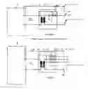
- 2) For instance, in transmitting situation no signal high enough can be achieved between 230 V 50 Hz phase and zero rail (L-N) of the electric net, since energy consuming apparatuses cause on the signal frequency a quite a strong load, i.e. low load impedance ZLOAD. This is influenced by the fact that there is from the transmitting apparatus a long cable connection (the equivalent series impedance ZW of the cable is high on signal frequency) to above phase and zero rail. According to the principle of voltage distribution the ULOAD is then low, i.e. the situation is bad. FIG. 1 shows the attenuation impact of the cable in a traditional solution, when the ZLOAD=1 ohm.
In the more developed modern techniques the problem presented in pos. 1) is already solved so that the outgoing signal of the transmitter remains almost constant, i.e. independent of the net impedance. However, it doesn't be of any help on resolving the problem of pos. 2), because of the series impedance ZW of the connecting cable of the apparatus and/or the cable and of the low load impedance ZLOAD between phase and zero rail in the electric net. There is a surprisingly good solution to the problem in this invention, where the impact of attenuation on the signal of the series impedance ZW of the connecting cable is eliminated almost completely.
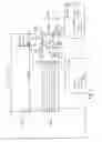
FIG. 2 shows the impact of attenuation the cable in the invention, when the ZLOAD is 1 ohm.
In transmitting situation it is decisive that for instance the “rail signal” ULOAD of the fuse box of an apartment, which is the signal voltage between phase rail L and zero rail N in fuse box UL-N, is as high as possible even with low ZLOAD values of the load impedance.
The apparatus as per the invention is characterized in that the equipment is divided into two or several parts, at least in a first part (3) and a second part (TX/REMU), whereby the second part (TX/REMU) includes at least a connecting unit (50) for connection to the electric net and a connecting cable for connection of said part to the electric net, whereby the length LW of the connecting cable is under 5 meters.
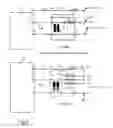
The invention is based on that an apparatus operating in the electric net is in a way divided into two parts, of which the first part comprises most suitably the equipment to form and adjust the signal and the second part comprises a transmitter a remote unit, hereafter called TX/REMU. The transmitter remote unit TX/REMU is placed as close as possible to the wall outlet of an electric net 230 V, 50 Hz or to a phase and zero rail for instance in a fuse box. The length of the connecting cable is held as small as possible, e.g. LW is under 5 meters or more suitably under 3 meters or even under 1 meter, as shown in FIG. 4. Possibly the transmitter remote unit TX/REMU can be placed in the voltage rail or even plugged in a wall outlet, if regulations allow. Then there is no connecting cable and the LW is 0 meter. The first part of the apparatus can be placed even far from the remote unit, the distance can be tens or even hundreds of meters. On the other hand the first part can be placed also close to the remote unit, even as a common unit with the remote unit.
The invention is disclosed with reference to the enclosed drawing figures, where
FIG. 1 shows the attenuation impact of the cable in a traditional solution, when the ZLOAD is 1 ohm.
FIG. 2 shows the attenuation impact of the cable in the invention, when the ZLOAD is 1 ohm.
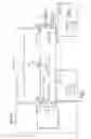
FIG. 3 shows a simple application of the invention.
FIG. 4 shows an effective application of the invention.
The transmitter remote unit TX/REMU gets the steering of its operation over the signal cable from the first part of the bipartitioned apparatus. The length LS of the signal cable can be tens and even hundreds of meters and has no impact on the size of the “rail signal” ULOAD, which is to be transmitted to the electric net. Refer FIGS. 2 and 4. The first part 3 and second part TX/REMU can be connected also wirelessly with an optical fibre cable or otherwise.
The transmitter remote unit TX/REMU is located for instance in a living room or in the main electric centre just beside the fuse box (fuses and phase rail and zero rail and switch) or in connection with it in its own box or in a wall outlet or near it. A cable comes to it from the fuse box rails over the fuse or from the wall outlet and, in addition, the signal cable from the first part of the apparatus, where generally the operation lights and switches are located.
The transmitter remote unit TX/REMU contains for instance a signal amplifier 20 (e.g. 95-125 kHz) low pass filter or band pass filter 40, but in any, case it contains a field unit connecting unit 50 for connection to the electric net. In addition, the remote unit TX/REMU can contain many other operation blocks and functions. It can also have a mains transformer and a voltage regulator.
The first part 3 of the apparatus can for instance in an apartment be placed in the signal cable end, even in a living room. Generally it includes the signal lights and operating switches and other operating switches and other operation means of the apparatus.
FIG. 3 shows a simple application of the invention and FIG. 4 a more efficient application of the invention.
The second part, remote unit TX/REMU, of the transmitter must be as to its mechanics as small as possible and suitably shaped, so that it could be utilized appropriately in the main electric centre of an apartment house or in the kWh-meter closet, for instance. There is not often much place available. The connecting cable taken to the phase and zero rail L, N or to a wall outlet must be as short as possible (e.g. LW=under 1 m). Regulations restricting the assembly must be taken into consideration.
Claims
1. A transmitter for sending a data transmission signal to many kinds of electric nets, whereby the apparatus comprises signal-shaping and adjustment devices (3) and connecting devices (50) including necessary accessories for connection to the electric net, as a signal amplifier (20) and a connecting cable and/or connecting device between the transmitter and the connecting point of the electric net, as for instance 230 V, 50 Hz phase rail (L) and zero rail (N) of the electric net or wall outlet as connecting points, characterized in that the apparatus is divided into two or several parts, at least a first part (3) and a second part (TX/REMU), whereby second part (TX/REMU) includes at least a connecting unit (50) for connection to the electric net and a connecting cable and/or connecting device for connecting said second part to the electric net, whereby the length (LW) of connecting cable is under 5 m.
2. A transmitter according to claim 1 characterized in that length of connecting cable is under 1 m. or, when remote unit (TX/REMU) is plugged in the wall outlet or connectable with a plug or fitted in phase and zero rails there is no connecting cable, in other words the length (LW) is 0.
3. A transmitter according to claim 1 characterized in that first part (3) and second part (TX/REMU) are placed in the same equipment unit.
4. A transmitter according to claim 1 characterized in that second part (TX/REMU) is shaped into a remote unit with respect to first part (3) and their mutual distance (LS) is over 1 m.
5. A transmitter according to claim 1 characterized in that the signal input and connecting cable can be connected to 1-phase rails (L), (N) in a direct-current network or an alternating-current network or to a wall outlet or another corresponding connection point.
6. A transmitter according to claim 1 characterized in that the signal input and connecting cable can be connected to 3-phase rails (L1,L2,L3), (N) or to a 3-phase outlet or another corresponding connection point.
7. A transmitter according to claim 1 characterized in that the connection between first part (3) and second part (TX/REMU) is wired, wireless or an optical fibre cable connection.
Images & Drawings included:
Sources:
- United States Patent and Trademark Office - verify current appl. status at the USPTO↗
Recent applications in this class:
- » 20240405801 2024-12-05
Variable Impedance Circuit - » 20240313825 2024-09-19
CIRCUIT STRUCTURE TO IMPROVE RELIABILITY OF POWER LINE COMMUNICATION - » 20240072845 2024-02-29
MOBILE DEVICES, MOBILE SYSTEMS AND OPERATING METHODS THEREOF - » 20240039579 2024-02-01
Low Frequency Communication System over Power Lines - » 20240030965 2024-01-25
Variable impedance circuit - » 20230421203 2023-12-28
Noise mitigation in single-ended links - » 20230412213 2023-12-21
CONFIGURABLE, POWER SUPPLY VOLTAGE REFERENCED SINGLE-ENDED SIGNALING WITH ESD PROTECTION - » 20230412212 2023-12-21
Power line communication (PLC) denial of service attack - » 20230239004 2023-07-27
Power-line/communication system - » 20230198574 2023-06-22
TRANSMISSION SYSTEM