Low profile motor
US20060214532A1
2006-09-28
10/552,245
2003-12-26
✅ Patent granted
US 7,675,214 B2
2010-03-09
WO; PCT/JP03/16878; 20031226
WO; WO2005/067125; 20050721
Thiem Phan
2025-05-05
Abstract:
A low-profile motor includes a rotor yoke (2) having a rotor magnet (3) on its inner or outer surface and being rotationally supported on a motor base (6) via a shaft, and a stator core (8) constituted of a plurality of T-shaped winding parts (9) each having an end (9a) opposed to the rotor magnet (3). On the motor base (6) formed with a hole (7a) for supporting the rotor yoke (2) via the shaft, the plurality of T-shaped winding parts (9) are cut like tongues along the radial direction of the hole (7a) and integrated, and the T-shaped winding parts (9) are each bent such that their ends (9a) are opposed to the rotor magnet (3). Thus, it is possible to readily form the T-shaped winding parts (9), eliminate the need for mounting the T-shaped winding parts (9), and reduce the number of parts and steps. This technique enables it to efficiently form an inexpensive low-profile motor for a magnetic disk unit and the like.
Assignee:
- PANASONIC CORPORATION 20,737 🇯🇵 Osaka, Japan
- Matsushita Electric Industrial Co., Ltd. 804 🇯🇵 Kadoma-shi, Japan
Interested in similar patents?
Get notified when new applications in this technology area are published.
Classification:
H02K1/146 » CPC main
Details of the magnetic circuit characterised by the shape, form or construction; Stationary parts of the magnetic circuit; Stator cores with salient poles consisting of a generally annular yoke with salient poles
G11B19/2009 » CPC further
Driving, starting, stopping record carriers not specifically of filamentary or web form, or of supports therefor; Control thereof; Control of operating function ; Driving both disc and head; Driving; Starting; Stopping; Control thereof Turntables, hubs and motors for disk drives; Mounting of motors in the drive
H02K1/185 » CPC further
Details of the magnetic circuit characterised by the shape, form or construction; Stationary parts of the magnetic circuit; Means for mounting or fastening magnetic stationary parts on to, or to, the stator structures to outer stators
H02K1/187 » CPC further
Details of the magnetic circuit characterised by the shape, form or construction; Stationary parts of the magnetic circuit; Means for mounting or fastening magnetic stationary parts on to, or to, the stator structures to inner stators
H02K5/1675 » CPC further
Casings; Enclosures; Supports; Casings or enclosures characterised by the shape, form or construction thereof; Means for supporting bearings, e.g. insulating supports or means for fitting bearings in the bearing-shields using sliding-contact or spherical cap bearings radially supporting the rotary shaft at only one end of the rotor
Y10T29/49009 » CPC further
Metal working; Method of mechanical manufacture; Electrical device making Dynamoelectric machine
Y10T29/49012 » CPC further
Metal working; Method of mechanical manufacture; Electrical device making; Dynamoelectric machine Rotor
Y10T29/4902 » CPC further
Metal working; Method of mechanical manufacture; Electrical device making Electromagnet, transformer or inductor
Y10T29/49071 » CPC further
Metal working; Method of mechanical manufacture; Electrical device making; Electromagnet, transformer or inductor by winding or coiling
Y10T29/49073 » CPC further
Metal working; Method of mechanical manufacture; Electrical device making; Electromagnet, transformer or inductor by assembling coil and core
H02K7/00 IPC
Arrangements for handling mechanical energy structurally associated with dynamo-electric machines, e.g. structural association with mechanical driving motors or auxiliary dynamo-electric machines
H02K5/00 IPC
Casings; Enclosures; Supports
H02K1/06 IPC
Details of the magnetic circuit characterised by the shape, form or construction
Description
TECHNICAL FIELDThe present invention relates to a low-profile motor used for a magnetic disk unit and the like and a method of manufacturing the same.
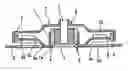
BACKGROUND ARTAs shown in FIG. 3, in a conventional low-profile motor used for a magnetic disk unit or the like, a rotator unit A is configured such that a rotor yoke 2 is fixed to a shaft 1 and a rotor magnet 3 are attached to the inner surface of the rotor yoke 2. A bearing unit B is constituted of a radial bearing 4 for supporting the shaft 1 in the radial direction and a thrust bearing 5 for supporting the shaft 1 in the axial direction. The bearing unit B is fit and fixed into a hole 7a of a cylindrical motor mounting part 7 which is formed on a motor base 6, the inner edge of a stator core 8 is bonded and fixed to a step 7b on the outer surface of the motor mounting part 7, and ends 9a of a plurality of T-shaped winding parts 9 of the stator core 8 are opposed to the rotor magnets 3, respectively. With this configuration, by energizing windings 10 on the T-shaped winding parts 9, a magnetic field is generated on the stator core 8, the rotor magnets 3 are excited, and a running torque can be generated on the rotor yoke 2.
As shown in FIG. 4, in the stator core 8, the T-shaped winding parts 9 extend radially from a ring part fit onto the motor mounting part 7 and the arc-shaped ends 9a of the T-shaped winding parts 9 are arranged in the circumferential direction. Conventionally, the stator core 8 is formed of a stack of stator plates. The stacking step and the step of mounting the stator core 8 on the motor mounting part are complicated and time consuming.
The present invention is devised to solve the problem and has as its object the provision of a low-profile motor in which a stator core can be readily formed and mounted.
DISCLOSURE OF THE INVENTIONIn order to attain the object, according to the first aspect of the invention, a low-profile motor is provided, which comprises a rotor yoke having a rotor magnet on its inner surface or outer surface and being rotationally supported on a motor base via a shaft, and a stator core constituted of a plurality of winding parts each having an end opposed to the rotor magnet, wherein on the motor base where a hole for supporting the rotor yoke via the shaft is formed, the plurality of winding parts constituting the stator core are cut like tongues along the radial direction of the hole and integrated, and each of the winding parts is bent such that the end of the winding part is opposed to the rotor magnet. Thus, it is possible to readily form the winding parts of the stator core, eliminate the need for mounting the stator core, and reduce the number of parts and steps.
According to the second aspect of the invention, in the low-profile motor configured as mentioned above, the motor base includes the plurality of winding parts is entirely formed of a silicon steel plate. Since the winding parts are integrated with the motor base, the electrical characteristics of the winding parts constituting the stator core is not impaired.
According to the third aspect of the invention, a manufacturing method is provided for a low-profile motor which comprises a rotor yoke having a rotor magnet on its inner surface or outer surface and being rotationally supported on a motor base via a shaft, and a stator core constituted of a plurality of winding parts each having an end opposed to the rotor magnet. The method comprises forming on the motor base a hole for supporting the rotor yoke via the shaft, cutting the plurality of winding parts constituting the stator core to be like tongues along the radial direction of the hole and integrating these winding parts on the motor base, and bending each of the winding parts such that the end of each winding part is opposed to the rotor magnet. Hence, it is possible to simplify the manufacturing process and achieve an inexpensive low-profile motor with high manufacturing efficiency as compared with the conventional method of separately forming and mounting a stator core on a motor base.
According to the fourth aspect of the invention, in the method of manufacturing the low-profile motor mentioned above, the step of cutting the plurality of winding parts on the motor base and the step of bending the winding parts are performed by press processing. It is possible to perform the steps at once, thereby further simplifying the manufacturing process.
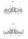
BRIEF DESCRIPTION OF THE DRAWINGSFIG. 1 is a sectional view showing a low-profile motor of outer rotor type according to Embodiment 1 of the present invention;
FIG. 2 is a sectional view showing a low-profile motor of inner rotor type according to Embodiment 2 of the present invention;
FIG. 3 is a sectional view showing a conventional low-profile motor; and
FIG. 4 is plan view showing a conventionally used stator core.
BEST MODE FOR CARRYING OUT THE INVENTIONThe following will describe embodiments of the present invention in accordance with the accompanying drawings.
Embodiment 1FIG. 1 is a sectional view showing a low-profile motor according to Embodiment 1 of the present invention. In FIG. 1, members having the same operations as those of the conventional low-profile motor shown in FIG. 3 will be indicated by the same reference numerals as FIG. 3.
As shown in FIG. 1, the low-profile motor is an outer rotor motor almost identical in configuration to the conventional low-profile motor shown in FIG. 3. A rotator unit A is configured such that a rotor yoke 2 is fixed to a shaft 1 and rotor magnets 3 are attached to the inner surface of the rotor yoke 2. A bearing unit B is constituted of a radial bearing 4 for supporting the shaft 1 in the radial direction and a thrust bearing 5 for supporting the shaft 1 in the axial direction.
The shaft 1 of the rotator unit A is inserted into the bearing unit B which is fit and fixed into a hole 7a of a cylindrical motor mounting part 7 of a motor base 6. In the rotor yoke 2 of the rotator unit A, a stator core 8 constituted of a plurality of T-shaped winding parts 9 is disposed such that arc-shaped ends 9a of the T-shaped winding parts 9 are opposed to the rotor magnets 3. Windings 10 are wound around portions near the ends 9a of the T-shaped winding parts 9.
The low-profile motor is different from the conventional motor in that the plurality of T-shaped winding parts 9 are cut like tongues along the radial direction of the motor mounting part 7 and integrally formed on the motor base 6 where the cylindrical motor mounting part 7 is formed in the above manner, and the T-shaped winding parts 9 are bent like letter L with the ends 9a opposed to the rotor magnets 3. Openings 6a formed by cutting and bending the T-shaped winding parts 9 are filled with filling members 6b.
To be specific, on a flat part of the motor base 6 extending from the lower end of the motor mounting part 7 to the outside, the T-shaped winding parts 9 are cut to the inside along the radial direction of the motor mounting part 7 such that the ends 9a are positioned near the rotor magnets 3, and the T-shaped winding parts 9 are bent diagonally above at bent portions 9b and bent to the outside at bent portions 9c, so that the ends 9a are opposed to the rotor magnets 3. The motor base 6 including the T-shaped winding parts 9 is entirely formed of a silicon steel plate which is used conventionally as a material of the stator core 8.
In the production of the motor base 6, the cylindrical motor mounting part 7 and the plurality of T-shaped winding parts 9 are sequentially formed in the flow of press processing for sheet metal (silicon steel plate). In this flow, the step of cutting the plurality of T-shaped winding parts 9 like tongues and the step of bending the T-shaped winding parts 9 can be performed at once.
Therefore, it is possible to reduce the number of components and steps as compared with the conventional method of separately forming and mounting the stator core 8 on the motor base 6. Since the steps of the stator core make up a large proportion of the overall cost of the motor, the cost can be considerably reduced.
As described above, the motor base 6 including the T-shaped winding parts 9 is formed of a silicon steel plate, and thus the electrical characteristics of the T-shaped winding parts 9 constituting the stator core 8 is not impaired.
Current low-profile motors have a limitation of storage up to about two stator plates having a thickness of 0.2 mm in a 1-inch HDD and so on. The low-profile motors can be further reduced in size and thickness unlike the conventional art in which a stator core is formed of a stack of stator plates. In this case, the specification of windings is changed from that of a laminated stator core, so that the same characteristic as the laminated stator core can be obtained.
Embodiment 2FIG. 2 is a sectional view showing a low-profile motor according to Embodiment 2 of the present invention. The low-profile motor is an inner rotor motor having the same configuration as the above-described low-profile motor. In the configuration of the low-profile motor, T-shaped winding parts 9 are cut to the outside along the radial direction of a motor mounting part 7 on a flat part of a motor base 6 such that ends 9a of the T-shaped winding parts 9 are positioned near rotor magnets 3, and each of the T-shaped winding parts 9 is bent diagonally above at a bent portion 9d and bent to the inside at a bent portion 9e.
The shape of the motor mounting part 7 is not limited to a cylinder as long as the motor mounting part 7 has a hole 7a where a bearing unit B can be fit and fixed. In addition to the press processing, a method such as metal injection is available to form the motor base 6.
As described above, in the low-profile motor of the present invention, a plurality of winding parts constituting a stator are cut and integrally formed on a motor base, and the winding parts are bent such that the ends of the winding parts are opposed to rotor magnets. Thus, it is possible to achieve a small thickness, high manufacturing efficiency, and low cost as compared with the conventional art.
Claims
1. A low-profile motor, comprising a rotor yoke having a rotor magnet on an inner surface or an outer surface and being rotationally supported on a motor base via a shaft, and a stator core constituted of a plurality of winding parts each having an end opposed to the rotor magnet, wherein
the plurality of winding parts constituting the stator core are cut to be like tongues along a radial direction of a hole and integrated, the hole having been formed on the motor base to support the rotor yoke via the shaft, and each of the winding parts is bent such that the end of the winding part is opposed to the rotor magnet.
2. The low-profile motor according to claim 1, wherein the motor base includes the plurality of winding parts is entirely formed of a silicon steel plate.
3. A method of manufacturing a low-profile motor comprising a rotor yoke having a rotor magnet on an inner surface or an outer surface and being rotationally supported on a motor base via a shaft, and a stator core constituted of a plurality of winding parts each having an end opposed to the rotor magnet, wherein
the method comprises:
forming, on the motor base, a hole for supporting the rotor yoke via the shaft;
cutting the plurality of winding parts constituting the stator core, to be like tongues along a radial direction of the hole, and integrating the winding parts on the motor base; and
bending each of the winding parts such that the end of the winding part is opposed to the rotor magnet.
4. The method of forming a low-profile motor according to claim 3, wherein the step of cutting the plurality of winding parts on the motor base and the step of bending the winding parts are performed by press processing.
Images & Drawings included:

Sources:
- United States Patent and Trademark Office - verify current appl. status at the USPTO↗
Similar patent applications:
- » 20160156248
Low Profile Motor - » 10262628
Low profile motor - » 20150305565
Low profile motor for portable appliances - » 20240405616
Low Profile Motor Using Permanent Magnets - » 10220371
Magnetic disk device having a low-profile motor without deterioration in the strength of the enclosure - » 20110248128
Low Profile Motorize Tilt Mount - » 10677205
Low-profile stepping motor with two coils arranged flush with each other horizontally - » 10672256
Low-profile stepping motor with two coils arranged flush with each other horizontally - » 10825274
Low-profile stepping motor having coils wound rectangularly - » 10661260
Low-profile, coreless motor
Recent applications in this class:
- » 20250219478 2025-07-03
STATOR AND MOTOR - » 20250219477 2025-07-03
MAGNETIC CORE, COIL-EQUIPPED MAGNETIC CORE, AND ROTARY ELECTRIC MACHINE - » 20250219476 2025-07-03
ROTATING ELECTRIC MACHINE - » 20250219475 2025-07-03
ELECTRIC MACHINE WITH MULTIPLE TOOTHED SPACERS IN COILS - » 20250219474 2025-07-03
STATOR CORE, MANUFACTURING METHOD FOR STATOR, AND ROTARY ELECTRIC MACHINE - » 20250211035 2025-06-26
MAGNETIC CORE AND METHOD FOR MANUFACTURING THE SAME, MAGNETIC CORE WITH COIL, AND ROTARY ELECTRIC MACHINE - » 20250125670 2025-04-17
ELECTRIC MOTOR AND HANDWHEEL ACTUATOR ASSEMBLY INCORPORATING A MOTOR - » 20250125669 2025-04-17
ELECTRIC MOTOR AND HANDWHEEL ACTUATOR ASSEMBLY INCORPORATING A MOTOR - » 20250088047 2025-03-13
ELECTRICAL MACHINE - » 20250088046 2025-03-13
ELECTRICAL MACHINE
Recent applications for this Assignee:
- » 20250038213 2025-01-30
SLURRY FOR NON-AQUEOUS ELECTROLYTE SECONDARY CELL, METHOD FOR MANUFACTURING SLURRY FOR NON-AQUEOUS ELECTROLYTE SECONDARY CELL, ELECTRODE FOR NON-AQUEOUS ELECTROLYTE SECONDARY CELL, AND NON-AQUEOUS ELECTROLYTE SECONDARY CELL - » 20230388751 2023-11-30
Information providing method and information providing apparatus - » 20230187624 2023-06-15
Positive electrode active material for lithium ion secondary battery and lithium ion secondary battery - » 20220368162 2022-11-17
POWER TRANSMISSION COIL, POWER TRANSMISSION DEVICE, AND UNDERWATER POWER SUPPLY SYSTEMS - » 20220345978 2022-10-27
NETWORK CONTROL DEVICE, NETWORK CONTROL SYSTEM, AND NETWORK CONTROL METHOD - » 20220345847 2022-10-27
Information collecting method, communication control apparatus, and information collector apparatus - » 20220317284 2022-10-06
SURVEILLANCE SYSTEM, AND SURVEILLANCE METHOD - » 20220299596 2022-09-22
MONITORING DEVICE AND MONITORING METHOD - » 20220278402 2022-09-01
RECTANGULAR SECONDARY BATTERY - » 20220205908 2022-06-30
Cellulose composite determination method and apparatus for composite resin