Apparatus for supplying oil of reciprocating compressor
US20060216169A1
2006-09-28
11/013,392
2004-12-17
Abstract:
Disclosed is an apparatus for supplying oil of a reciprocating compressor, comprising: an oil cylinder installed at one side of a reciprocating compressor main body for linearly vibrating together with the compressor main body, an oil piston inserted in the oil cylinder and relatively moving according to the linear vibration of the oil cylinder and thus sucking an oil in the oil cylinder and pumping the oil into the compressor main body by varying pressure in the oil cylinder, a pair of springs installed in the oil cylinder for elastically supporting both ends of the oil piston and causing a continual relative movement of the oil piston according to the linear vibration of the oil cylinder and a spring fixing means fixing the pair of springs for maintaining a certain interval with an inner circumferential surface of the oil cylinder, which results in reducing damage due to friction between the oil cylinder and the springs and in improving an oil supplying function.
Interested in similar patents?
Get notified when new applications in this technology area are published.
Classification:
F04B35/045 » CPC main
Piston pumps specially adapted for elastic fluids and characterised by the driving means to their working members, or by combination with, or adaptation to, specific driving engines or motors, not otherwise provided for the means being electric using solenoids
F04B39/0292 » CPC further
Component parts, details, or accessories, of pumps or pumping systems specially adapted for elastic fluids, not otherwise provided for in, or of interest apart from, groups -; Lubrication; Constructional details, e.g. reservoirs in the casing Lubrication of pistons or cylinders
F04B17/04 IPC
Pumps characterised by combination with, or adaptation to, specific driving engines or motors driven by electric motors using solenoids
Description
BACKGROUND OF THE INVENTION1. Field of the Invention
The present invention relates to an apparatus for supplying oil of a reciprocating compressor, and particularly, to an apparatus for supplying oil of a reciprocating compressor capable of improving an oil-supplying function and of preventing damage due to friction.
2. Description of the Conventional Art
In general, a reciprocating compressor is a device constructing an air conditioning device by which a refrigerant gas is sucked in the compressor depending on a straight line reciprocation of a piston in a cylinder and the compressed refrigerant gas is discharged out of the compressor.
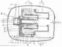
FIG. 1 is a longitudinal sectional view showing an example of the conventional reciprocating compressor. As shown in FIG. 1, the conventional reciprocating compressor is comprised of: a casing 10 filled with a certain amount of oil at an inner bottom surface thereof and communicated with a gas suction pipe SP and a gas discharge pipe DP; a frame unit elastically installed in the casing 10; a reciprocating motor 30 fixed to the frame unit 20, for linearly reciprocating a mover 33; a compression unit 40 coupled to the mover 33 of the reciprocating motor 30 and supported by the frame unit 20; a resonant spring unit 50 for elastically supporting the mover 33 of the reciprocating motor 30 in a direction of a movement thereof, thereby inducing a resonant motion; and an oil supplying unit 60 mounted on the frame unit 20, for pumping the oil filled in the inner bottom of the casing 10 to a friction generating portion of the compression unit 40.
The frame unit 20 includes: a front frame 21 for supporting the compression unit 40 and supporting a front side of the reciprocating motor 30; a middle frame 22 coupled to the front frame 21, for supporting a rear side of the reciprocating motor 30; and a rear frame coupled to the middle frame 22, for supporting the resonant spring unit 50.
The reciprocating motor 30 includes: an outer stator 31 installed between the front frame 21 and the middle frame 22; an inner stator 32 coupled to the outer stator 31 with a certain interval and insertion-installed at a cylinder 41 fixed to the front frame 21; and a mover 33 installed between the outer stator 31 and the inner stator 32, for linearly reciprocating.
The compression unit 40 includes: the cylinder 41 fixedly-installed at the front frame 21; a piston 42 coupled to the mover 33 of the reciprocating motor 30, for reciprocating at a compression space P of the cylinder 41; a suction valve 43 mounted on an upper end of the piston 42, for restricting a suction of refrigerant gas, opening/closing a suction passage F of the piston 42; and a discharge valve assemble body 44 mounted on a discharge side of the cylinder 41, for restricting a discharge of the compressed gas, opening/closing the compression space P.
The resonant spring unit 50 includes: a front side resonant spring 51 for supporting the front side of a connection portion of the mover 33 and the piston 42 centering around the connection portion; and a rear side resonant spring 52 for supporting the rear side of the connection portion.
The oil supplying unit 60 includes: an oil pumping portion 61 mounted on one side of the frame unit 20, for pumping the oil in the casing 10, vibrating together with the frame unit 20; and an oil supplying passage portion 62 formed at the frame unit 20, for communicating an outlet side of the oil pumping portion 61 and the compression unit 40.
The oil pumping portion 61 includes: an oil cylinder 61A mounted on an outer circumferential surface of one side of the front frame 21; an oil piston 61B slidingly-inserted in the oil cylinder 61A, for pumping the oil; a first oil spring 61C and a second oil spring 61D for elastically supporting both ends of the oil piston 61B; an oil valve 61E installed at a front surface of the front frame 21, for opening/closing a space between the oil cylinder 61A and the oil supplying passage portion 62; and an oil seat 61F and an oil cover 61G fixedly-installed at the front surface of the front frame 21 for taking in the oil valve 61E and forming an oil passage 61a therein which communicates the oil cylinder 61A and the oil supplying passage portion 62.
The first and second oil springs 61C and 61D are compressed and simply insertion-installed between both ends of the oil piston 61B and the oil cylinder 61A.
In FIG. 1, an unexplained reference numeral 61H refers to an oil suction pipe, and P refers to a compression space.
The aforementioned conventional reciprocating compressor will be operated as follows.
Once power is applied to the reciprocating motor 30 and thereby a flux is formed between the outer stator 31 and the inner stator 32, the mover 33 placed at a pore between the outer stator 31 and the inner stator 32 moves toward the direction of the flux, thereby continually reciprocating by the resonant spring unit 50. Also, the piston 42 reciprocates in the cylinder 41 and thus sucks refrigerant gas in the compression space P to discharge after compressing it. While this, the oil pumping portion 61 vibrates together with the frame unit 20 and thus pumps the oil in the casing 10 to thereby be supplied to the compression unit 40. Thereafter, sequential processes for recovering it back to the casing 10 are repeated.
Here, it will be described in detail how the oil in the casing 10 is supplied to the compression unit 40 as follows.
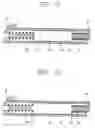
FIGS. 2 to 5 are sectional views showing installed states and operations of the conventional oil pumping portion 61.
First, referring to FIG. 2, when the oil cylinder 61A moves in a direction “A” in the drawing, the oil piston 61B relatively moves in an opposite direction (A′) with respect to the oil cylinder 61A. At this time, capacity of a space C of the oil cylinder 61A of the direction (A′) in which the oil piston 61B moves is increased and pressure in the space C is lowered. At the same time to this, a suction side of the oil valve 61E is opened and thereby new oil in the casing 10 is filled in the low pressure space C of the oil cylinder 61A through the oil suction pipe 61H.
Next, referring to FIG. 4, when the oil cylinder 61A moves in a direction “B” in the drawing, the oil piston 61D relatively moves in an opposite direction (B′) with respect to the oil cylinder 61A. At this time, capacity of the low pressure space C of the oil cylinder 61A is decreased and thus the pressure becomes high. As a result of this, the discharge side of the oil valve 61E is opened. At the same time to this, the oil having filled in the space C of the oil cylinder 61A is pushed out. The oil is then flowed in the oil supplying passage portion 62 through the oil passage 61a of the oil cover 61G, thereby being supplied to a friction generating portion placed between the cylinder 41 and the piston 42 of the compression unit 40 to serve as lubrication. Accordingly, when the oil supplying apparatus repeatedly moves, the first and second oil springs 61C and 61D installed in the oil cylinder 61A repeat a compression and an extension.
However, in the oil supplying apparatus of the conventional reciprocating compressor, since the first oil spring 61C and the second oil spring 61D are installed at both side surfaces of the oil piston 61B to be simply glued thereto, the two oil springs 61C and 61D are drooped to a lower portion of the oil cylinder 61A by gravity. As a result of this, as can be seen from FIGS. 3 and 5, as the first and second oil springs 61C and 61D repeat the compression and extension, frictional resistance is thereby occurred between the springs 61C and 61D and an inner circumferential surface of the oil cylinder 61A. Because of this, the oil piston is not smoothly slid, thereby degrading a lubricating performance.
Furthermore, ends of the first and second oil springs 61C and 61D are fit between edges of both sides of the oil piston 61B and the oil cylinder 61A, which interferes with sliding of the oil piston 61B and rubs an inner circumferential surface of the oil cylinder 61A. As a result, impurity is generated and combined is with the oil thereby to contaminate the refrigerant gas by being flowed in such a compressor portion.
SUMMARY OF THE INVENTIONTherefore, an object of the present invention is to provide an oil supplying apparatus for a reciprocating compressor constructed to be capable of improving a lubricating performance by preventing an oil spring from being contact with an oil cylinder due to a droop thereof.
Another object of the present invention is to provide an oil supplying apparatus for a reciprocating compressor capable of preventing an end of the an oil spring from being inserted between an oil piston and an oil cylinder.
To achieve these and other advantages and in accordance with the purpose of the present invention, as embodied and broadly described herein, there is provided an oil supplying apparatus for a reciprocating compressor, comprising: an oil cylinder installed at one side of a reciprocating compressor main body for linearly vibrating together with the compressor main body;
an oil piston inserted in the oil cylinder and relatively moving according to the linear vibration of the oil cylinder and thus sucking an oil in the oil cylinder and pumping the oil into the compressor main body by varying pressure in the oil cylinder, a pair of springs installed in the oil cylinder for elastically supporting both ends of the oil piston and causing a continual relative movement of the oil piston according to the linear vibration of the oil cylinder and a spring fixing means fixing the pair of springs for maintaining a certain interval with an inner circumferential surface of the oil cylinder.
The foregoing and other objects, features, aspects and advantages of the present invention will become more apparent from the following detailed description of the present invention when taken in conjunction with the accompanying drawings.
BRIEF DESCRIPTION OF THE DRAWINGSThe accompanying drawings, which are included to provide a further understanding of the invention and are incorporated in and constitute a part of this specification, illustrate embodiments of the invention and together with the description serve to explain the principles of the invention.
In the drawings:
FIG. 1 is a longitudinal sectional view showing an embodiment of a conventional reciprocating compressor;
FIG. 2 is a longitudinal sectional view showing an operating state of a conventional oil supplying apparatus;
FIG. 3 is an enlarged view showing the main part of FIG. 2;
FIG. 4 is a longitudinal sectional view showing an operating state of the conventional oil supplying apparatus;
FIG. 5 is an enlarged view showing the main part of FIG. 4;
FIG. 6 is a longitudinal sectional view showing a reciprocating compressor in accordance with an embodiment of the present invention;
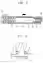
FIG. 7 is a longitudinal sectional view showing an operating state of an oil supplying apparatus in accordance with a first embodiment of the present invention;
FIG. 8 is an enlarged view showing the main part of FIG. 7;
FIG. 9 is a longitudinal sectional view showing an operating state of an oil supplying apparatus in accordance with the first embodiment of the present invention;
FIG. 10 is an enlarged view showing the main part of FIG. 9;
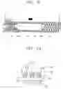
FIG. 11 is a longitudinal sectional view showing an oil supplying apparatus in accordance with a second embodiment of the present invention;
FIG. 12 is a longitudinal sectional view showing an oil supplying apparatus in accordance with a third embodiment of the present invention;
FIG. 13 is a longitudinal sectional view showing an oil supplying apparatus in accordance with a fourth embodiment of the present invention;
FIG. 14 is a longitudinal sectional view showing an oil supplying apparatus in accordance with a fifth embodiment of the present invention; and
FIG. 15 is a longitudinal sectional view showing an oil supplying apparatus in accordance with a sixth embodiment of the present invention.
DETAILED DESCRIPTION OF THE PREFERRED EMBODIMENTSReference will now be made in detail to the preferred embodiments of the present invention, examples of which are illustrated in the accompanying drawings.
Hereinafter, it will be explained of an oil supplying apparatus for a reciprocating compressor according to the present invention with reference to the attached drawings. Also, the same reference numeral will be used in a construction same to that of the conventional art.
There may exist various embodiments for an oil supplying apparatus for a reciprocating compressor according to the present invention. Hereinafter, the most preferred embodiment therefor will be explained.
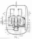
FIG. 6 is a longitudinal sectional view showing an oil supplying apparatus for a reciprocating compressor in accordance with an embodiment of the present invention, and FIGS. 7 through 15 show a plurality of embodiments for the oil supplying apparatus for a reciprocating compressor according to the present invention.
As shown in those drawings, a reciprocating compressor having an oil supplying apparatus includes: a casing 10 filled with a certain amount of oil at an inner bottom surface thereof and with which a gas suction pipe SP and a gas discharge pipe DP are communicated; a compressor main body 200 elastically mounted in the casing 10; and the oil supplying apparatus 100 mounted on one side of the compressor main body 200, for pumping the oil filled in the bottom surface of the casing 10 to a friction generating portion of the compressor main body 200.
The compressor main body 200 includes: a frame unit 20 elastically installed in the casing 10; a reciprocating motor 30 fixed to the frame unit 20, for linearly reciprocating a mover 33; a compression unit 40 coupled to the mover 33 of the reciprocating motor 30 and supported by the frame unit 20; and a resonant spring unit 50 for inducing a resonant motion by elastically supporting the mover 33 of the reciprocating motor 30 in a direction of a movement thereof.
The frame unit 20 includes: a front frame 21 for supporting the compression unit 40 and supporting a front side of the reciprocating motor 30; a middle frame 22 coupled to the front frame 21, for supporting a rear side of the reciprocating motor 30; and a rear frame coupled to the middle frame 22, for supporting the resonant spring unit 50.
The reciprocating motor 30 includes: an outer stator 31 installed between the front frame 21 and the middle frame 22; an inner stator 32 coupled to the outer stator with a certain interval and insertion-installed at a cylinder 41 fixed to the front frame 21; and a mover 33 installed between the outer stator 31 and the inner stator 32, for linearly reciprocating.
The compression unit 40 includes: the cylinder 41 fixedly-installed at the front frame 21; a piston 42 coupled to the mover 33 of the reciprocating motor 30, for reciprocating at a compression space P of the cylinder 41; a suction valve 43 mounted on an upper end of the piston 42, for restricting a suction of a refrigerant gas, opening/closing a suction passage F of the piston 42; and a discharge valve assemble body 44 mounted on a discharge side of the cylinder 41, for restricting a discharge of the compressed gas, opening/closing the compression space P.
The resonant spring unit 50 includes: a front side resonant spring 51 for supporting the front side of a connection portion of the mover 33 and the piston 42 centering around the connection portion; and a rear side resonant spring 52 for supporting the rear side of the connection portion.
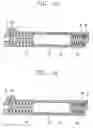
Referring to FIGS. 7 through 10, the oil supplying apparatus 100 in accordance with a first embodiment of the present invention includes: an oil cylinder 111 installed at one side of a reciprocating compressor main body 200 for linearly vibrating together with the compressor main body 200, an oil piston 112 inserted in the oil cylinder and relatively moving according to the linear vibration of the oil cylinder 111 and thus sucking an oil in the oil cylinder 111 and pumping the oil into the compressor main body 200 by varying pressure in the oil cylinder 111, a pair of springs 113 installed in the oil cylinder 111 for elastically supporting both ends of the oil piston 112 and causing a continual relative movement of the oil piston 112 according to the linear vibration of the oil cylinder 111 and a spring fixing means 112a fixing the pair of springs 113 for maintaining a certain interval with an inner circumferential surface of the oil cylinder 111.
The oil cylinder 111 is mounted on an outer circumferential surface of a lower portion of the front frame 21.
Also, an oil valve 115 for opening/closing a compression oil supplying passage 120 formed at the frame unit 20 is installed at a front surface of the front frame 21 in order to communicate the oil cylinder 111 and the compressor main body 200, particularly the compression unit 40. An oil seat 116 and an oil cover 117 having an oil passage 111a for taking in the oil valve 115 and simultaneously communicating the oil cylinder 111 and an oil supplying passage portion 120 are fixedly-installed at a front surface of the front frame 21.
The spring fixing means 112a is formed at both ends of the oil piston 112 in order to fix one end of each spring 114 contacting both side surfaces of the oil piston 112.
The spring fixing means 112a is protruded from both ends of the oil piston 112 to be inserted in an inner circumferential surface of one end of each spring 114. An external diameter of the spring fixing means 112a is preferably formed as same as or greater than an internal diameter of the spring 114 in order to be inserted with a forced fit into an inner circumferential surface of one end of each spring 114. At this time, the other end of each spring 114 is adhered closely to such as the front frame 21 or the middle frame 22 forming both side walls of the oil cylinder.
By fixing the springs 114 to the spring fixing means 112a, a certain interval t is formed between the outer circumferential surface of the springs 114 and the inner circumferential surface of the oil cylinder 111.
Hereinafter, FIGS. 11 through 15 show various embodiments of the oil supplying apparatus according to the present invention. Here, a detailed explanation of the same structure as the first embodiment will be omitted and the same reference numeral will be used.
FIG. 11 is a sectional view showing an oil supplying apparatus in accordance with a second embodiment of the present invention.
As shown in FIG. 11, a spring fixing means 117 of the oil supplying apparatus in accordance with the second embodiment of the present invention is formed as a groove recessed inwards of both ends of the oil piston at which each end of the springs 114 are insertion-fixed.
At this time, the groove is preferably formed to be as great as the outer diameter of one end of the spring 114. In order for the end of the spring 114 to be easily inserted, a surface contacting the outer circumferential surface of one end of each spring 114 is preferably formed to be inclined with a certain angle.
FIG. 12 shows an oil supplying apparatus in accordance with a third embodiment of the present invention.
Referring to FIG. 12, a spring fixing means 118 in accordance with the third embodiment of the present invention is formed as a groove recessed inwards of both ends of the oil piston 112 at which each end of the springs 114 are insertion-fixed. At this time, the groove has the same width as the diameter of the wire of the spring 114 and a part of both ends of the oil piston 112 are formed to be suitably inserted into an inner circumferential surface of one end of each spring 114. While this, a surface contacting the outer circumferential surface of one end of the spring 114 is preferably formed to be inclined with a certain angle.
FIGS. 13 and 14 show oil supplying apparatuses in accordance with fourth and fifth embodiments of the present invention, respectively.
A spring fixing means 119 and 200 of the oil supplying apparatus in accordance with the fourth and fifth embodiments of the present invention are formed in both inner side walls of the oil cylinder for fixing one end of each spring 114 contacting both inner side walls of both sides of the oil cylinder 111.
Referring to FIG. 13, the spring fixing means 119 according to the fourth embodiment is formed to be protruded from both inner side walls of the oil cylinder to be inserted into the inner circumferential surface of one end of each spring 114. At this time, preferably, they should be formed not to be an obstacle to an intake/discharge passage for air and oil formed in both inner side walls of the oil cylinder.
Also, referring to FIG. 14, the spring fixing means according to the fifth embodiment is formed as a groove recessed inwards of both side walls of the oil cylinder 111 in order for one end of the spring 114 to be insertion-fixed thereto. At this time, the groove has the same width as the diameter of the wire of the spring 114, and a part of both inner side walls of the oil cylinder 111 are preferably inserted into the inner circumferential surface of one end of the spring 114.
Here, both inner side walls of the oil cylinder 111, as shown in a typical drawing, are typically formed with the front frame 21 and the middle frame 22, however, it can be differently constructed depending on a design variation.
FIG. 15 shows an oil supplying apparatus in accordance with a sixth embodiment of the present invention.
Referring to FIG. 15, the spring fixing means of the oil supplying apparatus according to the sixth embodiment includes: a first fixing portion 122 formed in both ends of the oil piston 112 for fixing one end of each spring 114 contacting both ends of the oil piston 112; and a second fixing portion 123 formed in both inner side walls of the oil cylinder 111 for fixing one end of each spring 114 contacting both inner side walls of the oil cylinder 111.
That is, the spring fixing means according to the sixth embodiment can be formed in both ends of the oil piston 112 and both inner side walls of the oil cylinder 111.
In FIG. 15, there can be shown the first fixing portion 122 protruded from both ends of the oil piston 112 and the second fixing portion 123 formed as a groove recessed inwards of both inner side walls of the oil cylinder 111. However, the spring fixing means described in the first through fifth embodiments can be applicable for the first fixing portion 122 and the second fixing portion 123 shown in the sixth embodiment of the present invention.
The oil supplying apparatus for the reciprocating compressor according to the present invention, as aforementioned, has an operation effect, which will be described as follows.
Once power is applied to the reciprocating motor 30 and flux is formed between the outer stator 31 and the inner stator 32, the mover 33 moves toward a direction of the flux and continually reciprocates by the resonant spring unit 50. Also, the piston 42 sucks a refrigerant gas into the compression space P, compresses the refrigerant gas, and then discharges it while the piston 42 reciprocates in the cylinder 41. During this, oil is sucked through the oil supplying apparatus vibrating together with the compressor main body 200. Thereafter, the sucked oil is supplied to the compressor main body 200, particularly to the cylinder 41 and the piston 42 and then recollected back to the casing 10, which processes are repeated.
Here, it will be now described about a procedure how the oil is pumped in detail.
First, referring to FIG. 7, when the oil cylinder 111 vibrating depending on the linear vibration of the compressor main body 200 moves in a direction ‘C’, the oil piston 112 relatively moves in an opposite direction (C′) thereof. In response to this, the suction side of the oil valve 115 is opened. Next, when the oil cylinder 111, as shown in FIG. 9, moves in a direction ‘D’, the oil piston 112 relatively moves in an opposite direction (D′) thereof. In response to this, the discharge side of the oil valve 115 is opened.
While this, the pair of springs 114 may undesirably be contact with the oil cylinder 111 at the outer circumferential surface thereof while alternately repeating a compression and an extension in the oil cylinder 111 based on the movement direction of the oil piston 112. However, because the springs 114 are positioned having a certain interval t with an inner circumferential surface of the oil cylinder 111 by the spring fixing means formed in both ends of the oil piston 112 or both inner side walls of the oil cylinder 111, the springs 114 do not generate friction with the oil cylinder 111. As a result, the operation of the oil piston 112 in the oil cylinder 111 becomes smooth, thereby improving an oil supplying function.
Furthermore, because the spring fixing means are fixed, the ends of the springs 114 is prevented from being fit between the oil piston 112 and the oil cylinder 111, which results in preventing the oil cylinder 111 from detrition in advance. According to this, it is advantageous to prevent contamination of the oil due to the generation of impurity.
As the present invention may be embodied in several forms without departing from the spirit or essential characteristics thereof, it should also be understood that the above-described embodiments are not limited by any of the details of the foregoing description, unless otherwise specified, but rather should be construed broadly within its spirit and scope as defined in the appended claims, and therefore all changes and modifications that fall within the metes and bounds of the claims, or equivalence of such metes and bounds are therefore intended to be embraced by the appended claims.
Claims
What is claimed is:1. An apparatus for supplying oil of a reciprocating compressor, comprising:
an oil cylinder installed at one side of a reciprocating compressor main body for linearly vibrating together with the compressor main body;
an oil piston inserted in the oil cylinder and relatively moving according to the linear vibration of the oil cylinder and thus sucking an oil in the oil cylinder and pumping the oil into the compressor main body by varying pressure in the oil cylinder;
a pair of springs installed in the oil cylinder for elastically supporting both ends of the oil piston and causing a continual relative movement of the oil piston according to the linear vibration of the oil cylinder; and
a spring fixing means fixing the pair of springs for maintaining a certain interval with an inner circumferential surface of the oil cylinder.
2. The apparatus of claim 1, wherein the spring fixing means are formed in both ends of the oil piston for fixing one end of each spring contacting both side surfaces of the oil piston.
3. The apparatus of claim 2, wherein the spring fixing means are protruded from both ends of the oil piston in order to be inserted in an inner circumferential surface of one end of each spring.
4. The apparatus of claim 3, wherein the spring fixing means is inserted in the inner circumferential surface of each one end of the springs with a forcedly fit.
5. The apparatus of claim 2, wherein the spring fixing means is a groove recessed inwards of both ends of the oil piston in order for one end of each spring to be insertion-fixed thereto.
6. The apparatus of claim 1, wherein the spring fixing means is formed in both inner side walls of the oil cylinder for fixing one end of each spring contacting both inner side walls of the oil cylinder.
7. The apparatus of claim 6, wherein the spring fixing means is protruded from both inner side walls of the oil cylinder in order to be inserted in an inner circumferential surface of one end of each spring.
8. The apparatus of claim 6, wherein the spring fixing means is a groove recessed inwards of both side walls of the oil cylinder in order for one end of each spring to be insertion-fixed thereto.
9. The apparatus of claim 1, wherein the spring fixing means comprises:
a first fixing portion formed in both ends of the oil piston for fixing one end of each spring contacting both ends of the oil piston; and
a second fixing portion formed in both inner side walls of the oil cylinder for fixing one end of each spring contacting both inner side walls of the oil cylinder.
10. The apparatus of claim 9, wherein the first fixing portion is protruded from both ends of the oil piston to be inserted in the inner circumferential surface of one end of each spring.
11. The apparatus of claim 10, wherein the first fixing portion is inserted in the inner circumferential surface of one end of the spring with a forced fit.
12. The apparatus of claim 9, wherein the first fixing portion is a groove recessed inwards of both ends of the oil piston in order for one end of each spring to be insertion-fixed thereto.
13. The apparatus of claim 9, wherein the second fixing portion is protruded from both inner side walls of the oil cylinder to be inserted in the inner circumferential surface of one end of the spring.
14. The apparatus of claim 9, wherein the second fixing portion is a groove recessed inwards of both inner side walls of the oil cylinder in order for one end of the spring to be insertion-fixed thereto.
Images & Drawings included:


Sources:
- United States Patent and Trademark Office - verify current appl. status at the USPTO↗
Similar patent applications:
Recent applications in this class:
- » 20230213025 2023-07-06
Linear compressor and planar spring assembly - » 20230151802 2023-05-18
SYSTEMS AND METHODS FOR COMPRESSION AND EXPANSION OF GAS - » 20230074710 2023-03-09
Mechanical Resonant Pump - » 20230017414 2023-01-19
Compressor unit of a split stirling cryogenic refrigeration device - » 20220389920 2022-12-08
High Volume, Low Pressure Oilless Pump - » 20220389919 2022-12-08
Compressor - » 20220389918 2022-12-08
Compressor - » 20220154708 2022-05-19
Linear compressor - » 20220090590 2022-03-24
Linear compressor - » 20220065238 2022-03-03
Linear compressor