Method for fabricating a curved beam from composite material
US20060216480A1
2006-09-28
11/164,672
2005-12-01
✅ Patent granted
US 7,670,525 B2
2010-03-02
-
-
Steven P Griffin | Jacob Thomas Minskey
2028-08-14
Abstract:
This invention concerns a method for fabricating a curved beam from fiber composite material. A flat fiber composite laminate (2) comprising a plurality of layers and at least two different fiber directions is formed. The fiber composite laminate (2) is disposed in contact with a male tool (1) comprised of a first flange (1a), a second flange (1c) and an intermediate web (1b), which male tool (1) is curved in its longitudinal direction with a radius of curvature R in such a way that the first flange (1a) has a shorter longitudinal extent than the second flange (1c). The fiber composite laminate (2) is brought into contact with and secured to the first flange (1a) of the male tool (1). The male tool (1) and the fiber composite laminate (2) are then rotated relative to one another so that the fiber composite laminate (2) is brought into contact with the intermediate web (1b) of the male tool (1) in a first rotational movement, and brought into contact with the second flange (1c) of the male tool (1) in a second rotational movement. The fiber composite laminate (2) hardens on the male tool (1), and the finished beam is separated from the tool (1). The invention also relates to a beam of fiber composite material fabricated according to the method.
Inventors:
- Björn Weidmann 26 🇸🇪 Borensberg, Sweden
- Mikael Petersson 31 🇸🇪 Linkoping, Sweden
- Claes Rudqvist 5 🇸🇪 Linkoping, Sweden
- Max KROGAGER 20 🇸🇪 Linkoping, Sweden
Assignee:
- SAAB AB 412 🇸🇪 Linkoping, Sweden
Interested in similar patents?
Get notified when new applications in this technology area are published.
Classification:
B29C70/541 » CPC main
Shaping composites, i.e. plastics material comprising reinforcements, fillers or preformed parts, e.g. inserts comprising reinforcements only, e.g. self-reinforcing plastics; Shaping operations therefor; Component parts, details or accessories; Auxiliary operations, e.g. feeding or storage of prepregs or SMC after impregnation or during ageing Positioning reinforcements in a mould, e.g. using clamping means for the reinforcement
B29C70/32 » CPC further
Shaping composites, i.e. plastics material comprising reinforcements, fillers or preformed parts, e.g. inserts comprising reinforcements only, e.g. self-reinforcing plastics; Shaping operations therefor; Shaping by lay-up, i.e. applying fibres, tape or broadsheet on a mould, former or core; Shaping by spray-up, i.e. spraying of fibres on a mould, former or core on a rotating mould, former or core
B29C70/38 » CPC further
Shaping composites, i.e. plastics material comprising reinforcements, fillers or preformed parts, e.g. inserts comprising reinforcements only, e.g. self-reinforcing plastics; Shaping operations therefor; Shaping by lay-up, i.e. applying fibres, tape or broadsheet on a mould, former or core; Shaping by spray-up, i.e. spraying of fibres on a mould, former or core Automated lay-up, e.g. using robots, laying filaments according to predetermined patterns
B29C70/386 » CPC further
Shaping composites, i.e. plastics material comprising reinforcements, fillers or preformed parts, e.g. inserts comprising reinforcements only, e.g. self-reinforcing plastics; Shaping operations therefor; Shaping by lay-up, i.e. applying fibres, tape or broadsheet on a mould, former or core; Shaping by spray-up, i.e. spraying of fibres on a mould, former or core; Automated lay-up, e.g. using robots, laying filaments according to predetermined patterns Automated tape laying [ATL]
Y02T50/40 » CPC further
Aeronautics or air transport Weight reduction
Y02T50/40 » CPC further
Aeronautics or air transport Weight reduction
Y10T156/1036 » CPC further
Adhesive bonding and miscellaneous chemical manufacture; Methods of surface bonding and/or assembly therefor with permanent bending or reshaping or surface deformation of self sustaining lamina Bending of one piece blank and joining edges to form article
Y10T156/1043 » CPC further
Adhesive bonding and miscellaneous chemical manufacture; Methods of surface bonding and/or assembly therefor with permanent bending or reshaping or surface deformation of self sustaining lamina Subsequent to assembly
Y10T428/24124 » CPC further
Stock material or miscellaneous articles; Structurally defined web or sheet [e.g., overall dimension, etc.] including grain, strips, or filamentary elements in respective layers or components in angular relation Fibers
Y10T428/24628 » CPC further
Stock material or miscellaneous articles; Structurally defined web or sheet [e.g., overall dimension, etc.] Nonplanar uniform thickness material
B32B1/00 IPC
Layered products having a general shape other than plane
B28B7/22 IPC
Moulds; Cores; Mandrels Moulds for making units for prefabricated buildings, i.e. units each comprising an important section of at least two limiting planes of a room or space, e.g. cells ; Moulds for making prefabricated stair units
Description
FIELD OF THE INVENTIONThe invention concerns a method for fabricating a curved beam from fiber composite material. A flat fiber composite laminate comprising a plurality of layers and at least two different fiber directions is formed using the method according to the invention. The fiber composite laminate is disposed against a male tool comprising a first flange, a second flange and an intermediate web. The male tool is curved in its longitudinal direction with an angle of curvature R in such a way that the first flange has a shorter longitudinal extent than the second flange.
The invention also concerns a beam fabricated using the method according to the invention.
BACKGROUND OF THE INVENTIONThere is major demand for extended beams that combine low weight with high strength, particularly in the aviation industry. Meter-long beams are made from fiber composite material to support curved structures in aircraft fuselages. These fiber composite beams are given a shape that corresponds to the curved structure. A curvature with a radius of curvature R is thus imparted to the beams along at least a part of the longitudinal extent of the beam.
A male tool against which the fiber composite material is shaped before hardening is used in fabricating curved beams. The male tool can consist of a metal tool with a rectangular cross-section shaped so that a curvature is obtained in the longitudinal direction. The male tool has a first flange/side and a second opposing flange/side, both of which are curved in such a way that the flanges are parallel along their entire extents. One problem associated with the fabrication of curved beams using this type of tool is that it is difficult to get a laminate comprised of layers of fibers with different fiber directions to follow the curvature of the beam when the curvature is large, i.e. the radius of curvature R is small. Using current fabrication methods, the beam is fabricated in that a laminate is applied over the intermediate web and then brought down over the flanges of the tool. This fabrication method gives rise to the formation of folds at the curved surface of the tool that comprises the inner curved surface, i.e. the surface that faces in toward the center of the radius of curvature R. To prevent folds from being formed in a first flange that is formed against the first flange of the male tool, small wedge-shaped pieces of material are cut from the composite layer in that area. However, this entails a major waste of material and degraded strength in the finished beam. Supporting layers can be applied to the slit surface of the beam to mitigate the strength problem. However, one disadvantage of such supporting layers is that they increase the weight of the finished beam, which is undesirable, particularly in an aviation context.
SUMMARY OF THE INVENTIONAn object of the invention is to solve the foregoing problem.
The object is achieved by using a method of fabrication that comprises the steps of forming a flat fiber composite laminate comprised of a plurality of layers and at least two different fiber directions, the fiber composite laminate against a male tool comprised of a first flange, a second flange and an intermediate web, wherein the male tool is curved in its longitudinal direction with a radius of curvature R in such a way that the first flange has a shorter longitudinal extent than the second flange, applying and securing the fiber composite laminate to the first flange of the male tool, rotating the male tool and the fiber composite laminate relative to one another so that the fiber composite laminate is brought into contact with the intermediate web of the male tool in a first rotational movement, and brought into contact with the second flange of the male tool in a second rotational movement, hardening the fiber composite laminate on the male tool, and separating the finished beam from the male tool.
The invention also relates to a beam made from composite material in accordance with the aforementioned fabrication method.
The method according to the invention makes it possible to fabricate a beam with very little waste of material. Because the beam can be fabricated with no weak points in the form of slits, a beam with good strength properties is obtained.
BRIEF DESCRIPTION OF THE FIGURESThe invention, together with further objectives and advantages thereof, may best be understood by reference to the following description taken in conjunction with the accompanying drawings in which:
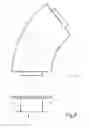
FIG. 1 shows a perspective view of a male tool;
FIG. 2 shows a tool with fiber composite laminate applied before shaping including the shaping of curved beams according to the state of the art; and
FIG. 3 shows the fabrication of curved beams using the method according to the invention.
DETAILED DESCRIPTION OF THE INVENTIONThe invention will be described below based on an embodiment in which the curved beam is shaped as a C-beam. It will be apparent that the same fabrication method can also be used for hat-shaped beams, Z-beams and I-beams.
FIG. 1 shows a perspective view of a male tool with a radius of curvature R. The tool can preferably consist of a homogeneous metal tool. Other materials and structures are of course also possible. The method according to the invention has been tested successfully using curve radii in excess of 2 meters and beam heights of up to 150 mm. It will be apparent to one skilled in the art that larger radii make it possible to work with higher beam heights while, in the same way, lower beam highs make it possible to work with smaller curve radii.
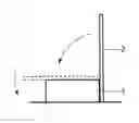
FIG. 2 depicts the shaping of a laminate 2 on a male tool 1 according to a prior art method. The laminate 2 is laid in contact with an intermediate web on the tool. The fiber composite laminate 2 is then brought down over each respective flange/side 1a, 1c of the tool so that the laminate 2 lies in contact with the entire extent of the tool. This known method causes folds to be formed at a first flange 1a of the tool, i.e. the side of the tool that forms the inner curve surface.
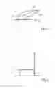
FIG. 3 shows the shaping process as per the method according to the invention. A flat fiber composite laminate 2 is brought into contact with a first flange 1a of the tool 1 and secured at said first flange 1a. The fiber composite laminate 2 is then pressed down toward the intermediate web 1b of the male tool 1 so that the fiber composite laminate is stretched out over the entire intermediate web. This draping process can be performed while the male tool 1 is being rotated relative to the fiber composite laminate, with the fiber composite laminate 2 being kept still. Other types of relative movement between the tool 1 and laminate 2 are, however, also possible. Tensile stress will consequently occur in the fiber composite laminate 2. The tensile stress in the laminate 2 increases with increasing distance from the first flange 1a. The highest tensile strength occurs in that part of the fiber composite laminate 2 that is in contact with the edge of the second flange 1c. The fiber composite laminate 2 is then brought toward the second flange 1c on the male tool 1. The tensile stress in the stretched fiber composite laminate 2 causes the laminate 2 to be pressed against the second flange 1c. After being draped onto the tool, the fiber composite 2 hardens to form a finished beam, e.g. via hardening in an autoclave. The finished beam is then removed from the tool 1.
The method according to the invention produces elongation of the laminate 2 so that the fiber density in the part of the laminate 2 that lies in contact with the second flange 1c is lower per unit of area than the fiber density in that part of the laminate 2 that lies in contact with the first flange 1a. Elongation of the material can be achieved by securing the fiber composite laminate 2 at the first flange 1a before the laminate 2 is draped over the tool. This elongation eliminates the known problem of fold formation associated with prior methods, while at the same time retaining high strength and low weight.
The method according to the invention has been described for the fabrication of a so-called C-beam. The method can however also be used to produced hat-shaped beams, Z-beams and I-beams. The method is applicable primarily to larger beams such as occur in an aviation context, and where a combination of high strength and low weight is essential.
The foregoing description of the preferred embodiments of the invention has been presented for purposes of illustration and description. It is not intended to be exhaustive or to limit the invention to the precise forms disclosed, since many modifications or variations thereof are possible in light of the above teaching. It is therefore the intention that the following claims not be given a restrictive interpretation but should be viewed to encompass variations and modifications that are derived from the inventive subject matter disclosed.
Claims
What is claimed is:1. A method for fabricating a curved beam from fiber composite material, comprising the steps of:
forming a flat fiber composite laminate (2) comprised of a plurality of layers and at least two different fiber directions,
arranging the fiber composite laminate (2) against a male tool (1) comprised of a first flange (1a), a second flange (1c) and an intermediate web (1b), wherein the male tool (1) is curved in its longitudinal direction with a radius of curvature R in such a way that the first flange (1a) has a shorter longitudinal extent than the second flange (1c),
applying and securing the fiber composite laminate (2) to the first flange (1a) of the male tool (1),
rotating the male tool (1) and the fiber composite laminate (2) relative to one another so that the fiber composite laminate (2) is brought into contact with the intermediate web (1b) of the male tool (1) in a first rotational movement, and brought into contact with the second flange (1c) of the male tool (1) in a second rotational movement,
hardening the fiber composite laminate (2) on the male tool (1), and
separating the finished beam from the male tool (1).
2. A method according to claim 1, wherein the fiber composite laminate (2) is stretched over the intermediate web (1b) during the first rotational movement so that the fiber density per unit of area becomes lower in the portion of the fiber composite laminate (2) that is arranged in contact with the second flange (1c) than in the portion of the fiber composite laminate (2) that is arranged in contact with the first flange (1a).
3. A method according to claim 1, wherein the flat fiber composite laminate (2) is laid up in equipment for automatic tape lay-up.
4. A method according to claim 1, wherein the curved beam is shaped as a C-beam.
5. A method according to claim 1, wherein the curved beam is shaped as a Z-beam.
6. A method according to claim 1, wherein the curved beam is shaped in a hat shape.
7. A method according to claim 1, wherein the curved beam is shaped as an I-beam.
8. A beam of fiber composite material fabricated according to a method comprising the steps of:
forming a flat fiber composite laminate (2) comprised of a plurality of layers and at least two different fiber directions,
arranging the fiber composite laminate (2) against a male tool (1) comprised of a first flange (1a), a second flange (1c) and an intermediate web (1b), wherein the male tool (1) is curved in its longitudinal direction with a radius of curvature R in such a way that the first flange (1a) has a shorter longitudinal extent than the second flange (1c),
applying and securing the fiber composite laminate (2) to the first flange (1a) of the male tool (1),
rotating the male tool (1) and the fiber composite laminate (2) relative to one another so that the fiber composite laminate (2) is brought into contact with the intermediate web (1b) of the male tool (1) in a first rotational movement, and brought into contact with the second flange (1c) of the male tool (1) in a second rotational movement,
hardening the fiber composite laminate (2) on the male tool (1), and
separating the finished beam from the male tool (1).
9. A beam according to claim 8 that has a curve corresponding to a part of an airplane fuselage and is included in a support structure for said part of the airplane fuselage.
Images & Drawings included:
Sources:
- United States Patent and Trademark Office - verify current appl. status at the USPTO↗
Recent applications in this class:
- » 20250222662 2025-07-10
MOLD PRECISION PINS FOR COMPONENT LOCATION DURING FABRICATION OF WIND TURBINE BLADES - » 20250214310 2025-07-03
METHOD FOR MANUFACTURING A PREFORM BUILDING ELEMENT AND MOLD ARRANGEMENT - » 20250100237 2025-03-27
MOLD ASSEMBLY FOR INFUSING A SPAR CAP AND RELATED METHODS - » 20250001710 2025-01-02
METHOD FOR INJECTING RESIN AND DEVICE FOR HOLDING A FIBER TEXTURE ON AN IMPREGNATION MANDREL OF A WINDING MACHINE - » 20240239060 2024-07-18
METHOD FOR PRODUCING GRINDING LIQUID MIXING TANK AND THE STRUCTURE THEREOF - » 20240025138 2024-01-25
IN-MOLD REFERENCE MARKERS TO ENHANCE THE CALIBRATION OF OPTICAL SYSTEMS IN MANUFACTURING WIND TURBINE BLADES - » 20240001633 2024-01-04
MOLDS AND METHODS FOR PRODUCING SEMI-PRODUCT AND HUB ASSEMBLY - » 20240001632 2024-01-04
METHOD OF MANUFACTURING A SPAR CAP FOR A WIND TURBINE BLADE - » 20230364867 2023-11-16
Device and method for manufacturing composite parts for an aircraft bulkhead - » 20230311435 2023-10-05
Methods and devices for supporting of variety of different pre-cured composite stringers
Recent applications for this Assignee:
- » 20250167442 2025-05-22
AN ANTENNA PLATFORM ARRANGEMENT - » 20240332786 2024-10-03
Pivotable connection device and a vehicle - » 20240272261 2024-08-15
Multi-channel active array system and method for obtaining positional information of an object - » 20240266755 2024-08-08
Method for operating wide-band AESA - » 20240210148 2024-06-27
LINER FOR A SHAPED CHARGE AND METHOD FOR MANUFACTURING A LINER - » 20240106417 2024-03-28
Single-pole double-throw radio-frequency switch topology - » 20240085186 2024-03-14
Method, software product, and system for determining a position and orientation in a 3D reconstruction of the earth's surface - » 20240085159 2024-03-14
Electronic countermeasure cartridge arranged to be loaded into countermeasure dispenser and arranged to irradiate dispensed electromagnetically reflective material - » 20240047871 2024-02-08
METHOD AND DEVICE FOR CONTROLLING THE OUTPUT EFFICIENCY OF A PLURALITY OF AMPLIFIERS - » 20240039208 2024-02-01
High voltage adapter