Refrigeration system and refrigeration method thereof
US20060225440A1
2006-10-12
11/101,919
2005-04-08
Abstract:
A refrigeration system and refrigeration method thereof utilizing the principle of thermodynamics comprises a compressor, an air cooler connected to the compressor, an expander having a first end connected to the air cooler, a second end connected to the compressor, and a third end as an outlet wherein air pressure and air temperature are increased by the compressor, the pressurized high temperature air is fed to the air cooler, the pressurized low temperature air is fed to the expander for converting enthalpy of air into work to activate the compressor, energy contained in the air at the outlet of the expander is decreased, and temperature at the outlet of the expander is decreased. According to the present invention power is recycled in the process of conversion.
Assignee:
- Lin-Yun Chou 1 🇹🇼 Fengshan City, Taiwan
Interested in similar patents?
Get notified when new applications in this technology area are published.
Classification:
F25B9/004 » CPC main
Compression machines, plants or systems, in which the refrigerant is air or other gas of low boiling point characterised by the refrigerant the refrigerant being air
F25B2400/14 » CPC further
General features or devices for refrigeration machines, plants or systems, combined heating and refrigeration systems or heat-pump systems, i.e. not limited to a particular subgroup of Power generation using energy from the expansion of the refrigerant
F25B9/00 IPC
Compression machines, plants or systems, in which the refrigerant is air or other gas of low boiling point
F25D9/00 IPC
Devices not associated with refrigerating machinery and not covered by groups - ; Combinations of devices covered by two or more of the groups -
Description
BACKGROUND OF THE INVENTION1. Field of Invention
The present invention relates to the field of mechanical refrigeration and more particularly to a refrigeration system and refrigeration method thereof in which air (i.e., the working fluid) is used as refrigerant.
2. Related Art
The technique of taking air as refrigerant is well known. In 1862, Stirling air engine was devised and which was later used for the development of ice machine.
Refrigerant used in prior vapor compression system is selected from some flammable or toxic components such as ethyl ether, ammonia, or sulphur dioxide. However, the flammable or toxic refrigerant may leak and thus the prior vapor compression systems are unable to be used in closed cabins such as ships. In 1877, J. J. Coleman invented a steam driven air-cycle refrigerator which was later successfully used in a commercial ship. Prior reciprocating compressor and expander are bulky as compared to the vapor compression system.
In addition, CFCs (chlorofluorocarbons) based refrigerant is relatively high in thermal efficiency. Thus, except in the field of aircraft, a refrigeration system having CFCs as refrigerant has replaced the air-cycle refrigeration system. The reason that the air-cycle refrigeration system used in aircrafts is irreplaceable is that due to the development of military aircraft and the application of thrusters in jet engines since World War II, the pressure in the cabin raises with the increasing height of flight. The pressure in the cabins is supplied by an engine compressor and thus the engine compressor is able to be used in the air-cycle refrigeration system. Recently, rotary air compressor and expander are available. Thus, continuing improvements in the exploitation of refrigeration system are constantly being sought.
SUMMARY OF THE INVENTIONIt is therefore an object of the present invention to provide a refrigeration system utilizing the principle of thermodynamics comprising a compressor, an air cooler connected to the compressor, an expander having a first end connected to the air cooler, a second end connected to the compressor, and a third end as an outlet, wherein air pressure and air temperature are increased by the compressor, the pressurized high temperature air is fed to the air cooler for cooling, the pressurized low temperature air is fed to the expander for converting enthalpy of air into work to activate the compressor, energy contained in the air at the outlet of the expander is decreased, and temperature at the outlet of the expander is decreased. According to the present invention power is recycled in the process of conversion.
It is another object of the present invention to provide a refrigeration method comprising the steps of employing a reversed Brayton cycle, making air being drawn into a compressor for compression by atmospheric pressure and constant-pressure cooling, and feeding the air from the compressor to an expander for isothermal expansion so as to decrease enthalpy of a body to a predetermined temperature.
The above and other objects, features and advantages of the present invention will become apparent from the following detailed description taken with the accompanying drawings.
BRIEF DESCRIPTION OF THE DRAWINGSFIG. 1 is a block diagram of a refrigeration system according to the invention;
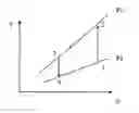
FIG. 2 is a T-S diagram of the refrigeration system of FIG. 1 where isentropic compression and isentropic expansion are plotted;
FIG. 3 shows details of the refrigeration system of FIG. 1;
FIG. 4 plots EER versus an air motor outlet temperature for different pressure ratios according to the invention;
FIG. 5 plots temperature difference versus pressure ratio for different volumetric flow rates and different isentropic processes according to the invention;
FIG. 6 plots isentropic efficiency versus pressure ratio according to the invention;
FIG. 7 plots temperature difference versus pressure ratio for different volumetric flow rates according to the invention;
FIG. 8 plots actual temperature difference versus pressure ratio according to the invention;
FIG. 9 plots isentropic efficiency versus volumetric flow rate according to the invention;
FIG. 10 plots isentropic efficiency versus temperature difference according to the invention;
FIG. 11 plots pressure ratio versus cooling capacity according to the invention;
FIG. 12 is a T-S diagram of the refrigeration system of FIG. 1 where isentropic compression and isentropic expansion versus actual compression and actual expansion are plotted for comparison;
FIG. 13 is another block diagram of the refrigeration system of FIG. 1 with power input and output being illustrated during refrigeration;
FIG. 14 plots temperature difference versus pressure ratio for isentropic process according to the invention;
FIG. 15 is a block diagram of a prototype refrigeration system according to the invention;
FIG. 16 is a T-S diagram of the prototype refrigeration system of FIG. 15 where isentropic compression and isentropic expansion versus actual compression and actual expansion are plotted for comparison;
FIG. 17 plots EER versus an air motor outlet temperature for different pressure ratios according to the invention;
FIG. 18 plots isentropic efficiency of an air motor versus ratio of outlet pressure to inlet pressure of the air motor for different volumetric flow rates according to the invention;
FIG. 19 plots outlet and inlet temperature difference of the air motor versus isentropic efficiency of the air motor for different volumetric flow rates according to the invention;
FIG. 20 plots outlet and inlet temperature difference of the air motor versus pressure ratio for different volumetric flow rates and different isentropic processes according to the invention; and
FIG. 21 plots cooling capacity versus pressure ratio for different volumetric flow rates according to the invention.
DETAILED DESCRIPTION OF THE INVENTIONReferring to FIGS. 1 and 2, there is shown a refrigeration system constructed in accordance with a preferred embodiment of the invention and a T-S diagram thereof respectively. The refrigeration system is designed based on reversed Brayton cycle. In FIG. 2, state 1 to state 2 is isentropic compression, state 2 to state 3 is constant-pressure cooling, and state 3 to state 4 is isentropic expansion.
It is assumed that the working fluid is air and which is ideal. Thus, equations about ideal gas can be applied:
PV=mRT Pv=RT P=ρRT (Equ. 1)
Also, specific heat at constant volume (Cv) is defined as below.
C
v
≡
∂
u
∂
T
(
Equ
.
2
)
For Cv(T) (i.e., temperature only) in ideal gas,
C
v
≡
ⅆ
u
ⅆ
T
(
Equ
.
3
)
Cv can be viewed as a constant when temperature difference is small. That is,
C
v
≡
u
2
-
u
1
T
2
-
T
1
(
Equ
.
4
)
specific enthalpy (Δh)
From and the law of conservation of energy
Δu=Q−W (Equ. 5)
can be derived if both kinetic energy change and potential energy change are omitted. Also,
W=PdV=P(V2−V1) (Equ. 6)
Thus, equation (5) can be rewritten as
Q=Δu+P(V2−V1)≡Δh (Equ. 7)
Also, specific heat at constant pressure (Cp) is defined as below.
C
p
≡
∂
h
∂
T
(
Equ
.
8
)
For Cp(T) (i.e., temperature only) in ideal gas,
C
p
≡
ⅆ
h
ⅆ
T
(
Equ
.
9
)
Cp can be viewed as a constant when temperature difference is small. That is,
C
p
≡
h
2
-
h
1
T
2
-
T
1
(
Equ
.
10
)
The process is reversible if both expansion and compression are in ideal states. That is,
γ
≡
C
p
C
v
(
Equ
.
11
)
Pνγ=C (Equ. 12)
From equation 1,
v
=
RT
P
(
Equ
.
13
)
is derived. Substitute equation 13 into equation 12
P
(
RT
P
)
γ
=
C
(
Equ
.
14
)
is obtained. Thus,
P
1
(
RT
P
1
)
γ
=
C
=
P
2
(
RT
P
2
)
γ
(
Equ
.
15
)
P
1
×
P
1
-
γ
×
R
γ
×
T
1
γ
=
P
2
γ
×
P
2
-
γ
×
R
γ
×
T
2
γ
(
Equ
.
16
)
P
1
1
-
γ
×
T
1
γ
=
P
2
1
-
γ
×
T
2
γ
(
Equ
.
17
)
(
T
2
T
1
)
γ
=
(
P
1
P
2
)
1
-
γ
(
Equ
.
18
)
T
2
T
1
=
(
P
1
P
2
)
1
-
γ
/
γ
=
(
P
2
P
1
)
γ
-
1
/
γ
(
Equ
.
19
)
Power required by a compressor is
Win={dot over (m)}×(h2−h1)={dot over (m)}×Cp×(T2−T1) (Equ. 20)
Cooling duty of air cooler is
{dot over (m)}×(h2−h3)={dot over (m)}×Cp×(T2−T3) (Equ. 21)
Expander output power is
Wout={dot over (m)}×(h3−h4)={dot over (m)}×Cp×(T3−T4) (Equ. 22)
Referring to FIG. 2 again, power required by a compressor is larger than power output of an expander since both pressure curves converge toward origin. Further, Win is required to be equal to Wout since both the compressor and the expander are driven by the same shaft. From equations 21 and 22, it is clear that power input or output can be changed by changing {dot over (m)} or temperature difference. From equation 19, it is clear that it is possible of changing pressure difference between inlet and outlet of expander or compressor by changing temperature difference. However, such technique is not applicable to refrigeration. Advantageously, increasing volumetric flow rate of the working fluid through the expander will achieve the purpose of the invention.
Typically, EER (energy efficiency ratio) is used for representing efficiency of an air conditioning system:
EER=[cooling capacity (Kcal/hr)]/[power consumption (W)] (Equ. 23)
Note that:
1 RT=3300 Kcal/hr (Equ. 24)
1 Kcal=4.1868 KJ (Equ. 25)
1 Kcal/hr=4.1868 KJ/hr (Equ. 26)
1 RT=13900.176 K/Jr=3.86 K/sec=3.86 KW (Equ. 27)
Now, it is assumed the following: Both compressor and expander have 100% of isentropic efficiency. Air is ideal gas. Pressure is absolute pressure. Temperature is absolute temperature scale. Referring to FIG. 3, details of the refrigeration system of the invention are shown.
| Atmos- | Atmos- | ||||
| pheric | pheric | ||||
| pressure | temperature | ||||
| (Patm) | (T∞) | Cp | R | Cv | Y |
| 1.0 bar | 303 K | 1.006 KJ/KgK | 287 J/KgK | 0.719 KJ/KgK | 1.4 |
Where P1=1.5 bar, {dot over (m)}A=0.05 Kg/sec, T3=298 K.
From equation 19, T1 and T2 can be obtained as follows:
T1/T∞=(P1/Patm)1−γ/γ=>(T1/303)=(1.5/1)0.285=>T1=340.117 K (Equ. 28)
T2/T3=(P2P3)1−γ/γ=>(T2 /298)=(1.5/1)0.285=>T2=334.505 K (Equ. 29)
No. 1 compressor work input is
Win1={dot over (m)}A×CP×(T1−T∞)=0.05×1.006×(340.117−303)=1.867 KW (Equ. 30)
For causing both No. 1 compressor and expander to have same power, volumetric flow rate must be adjusted. {dot over (m)}A and {dot over (m)}B can be obtained from the following equations:
{dot over (m)}A×CP×(T1−T∞)=({dot over (m)}A+{dot over (m)}B)×CP×(T2−T3) (Equ. 31)
{dot over (m)}A×1.006×(340.117−303)=({dot over (m)}A+{dot over (m)}B)×1.006×(334.505−298) (Equ. 32)
{dot over (m)}A=17.5{dot over (m)}B (Equ. 33)
Thus,
{dot over (m)}B=0.00083893 Kg/sec (Equ. 34)
No. 2 compressor work input is
Win2={dot over (m)}B×Cp×(T1−T∞)=0.00083893×1.006×(340.117−303)=0.031 KW (Equ. 35)
Cooling duty for air cooler is
({dot over (m)}A+{dot over (m)}B)×Cp×(T1−T2)=(0.05+0.00083893)×1.006×(340.117−334.505)=0.287 KW (Equ. 36)
Cooling capacity is
[({dot over (m)}A+{dot over (m)}B)×Cp×(T2−T3)×3600]/4.1868=[(0.05+0.00083893)×1.006×(334.505−298)=1605.328 Kcal/hr (Equ. 37)
EER1=Eq(37)/(Eq(35)+Eq(36))×1000=7.79 (Equ. 38)
EER without cooling duty is
EER2=Eq(37)/Eq(35)×1000=51.247 (Equ. 39)
Referring to FIG. 4, it plots EER versus an air motor outlet temperature for different pressure ratios according to the invention.
FIGS. 5 to 11 use graphs to illustrate properties of the refrigeration system of the invention. FIG. 12 is a T-S diagram of the refrigeration system of the invention. The working fluid of the refrigeration system of the invention is air which is taken as ideal gas. In FIG. 12, state 1 to state 2s is isentropic compression, state 2s to state 3 is constant-pressure cooling, state 3 to state 4s is isentropic expansion, state 1 to state 2 is actual compression, state 2 to state 3 is constant-pressure cooling, and state 3 to state 4 is actual expansion.
FIG. 13 is another block diagram of the refrigeration system of FIG. 1. In the refrigerating process, air pressure is increased by compressor in which temperature is also increased. Next, the pressurized high temperature air is fed to cooler for cooling. Next, the pressurized low temperature air is fed to expander for converting enthalpy of air into mechanical work to activate the compressor. Energy contained in air at expander outlet is thus decreased due to the conversion. As a result, temperature is decreased significantly, thereby achieving the purpose of refrigeration.
In FIG. 14, it plots temperature difference versus pressure ratio for isentropic process according to the invention. This graph is derived from the equation
T
3
T
4
S
=
(
P
1
P
2
)
1
-
γ
/
γ
=
(
P
2
P
1
)
γ
-
1
/
γ
.
It is found that the higher of pressure ratio the higher of the temperature difference at expander outlet. In FIG. 16, h2s−h1>h3−h4s. That is, work generated by the air motor is less than work required by compressor. Thus, extra power fed into compressor is required.
FIG. 15 is a block diagram of a prototype refrigeration system according to the invention and FIG. 16 is a T-S diagram of the prototype refrigeration system of FIG. 15 where isentropic compression and isentropic expansion versus actual compression and actual expansion are plotted for comparison. In FIG. 15, an additional No. 2 compressor is added to supply additional power to the refrigeration system for meeting the need. A tank for supplying activation power is also provided. After activating, air is drawn into the No. 1 compressor for compression. Pressurized air from the No. 1 compressor is combined with pressurized air fed from the No. 2 compressor prior to entering an air cooler and the tank sequentially. Next, air is fed to the air motor for driving. As a result, cool air is discharged at an air motor outlet (i.e., the purpose of refrigeration is achieved).
The refrigeration equation of the refrigeration system can be expressed as
{dot over (m)}B×(T2S−T2)=({dot over (m)}A+{dot over (m)}B)×(T3−T4S)−{dot over (m)}A(T2S−T1)
EER is thus obtained by the following equation:
EER
=
(
m
.
A
+
m
.
B
)
×
(
T
3
-
T
4
S
)
m
.
B
×
(
T
2
S
-
T
2
)
FIG. 17 plots EER versus the air motor outlet temperature for different pressure ratios according to the invention. It is found that EER increases as pressure ratio increases. Cooling capacity can be expressed by the following equation:
({dot over (m)}A+{dot over (m)}B)×(T3−T4S)(J/S)
Energy consumption can be expressed by the following equation:
{dot over (m)}B×(T2S−T1)(J/S)
Isentropic efficiency and EER of the refrigeration system of the invention are expressed as below. η = ( m . A + m . B ) × ( T 3 - T 4 ) ( m . A + m . B ) × ( T 3 - T 4 s ) ≅ 0.07 ∼ 0.095 EER = ( m . A + m . B ) × ( T 3 - T 4 S ) m . B × ( T 2 S - T 2 )
Referring to FIGS. 18 and 19, it is clear that the higher the pressure the higher the work done on blades of the air motor by itself will be. The higher of the temperature difference between the inlet and outlet of the air motor the higher the isentropic efficiency will be.
Referring to FIG. 20, it is clear that temperature increase in the range of 60□ and 70□ occurs for temperature difference between the inlet and outlet of the air motor versus pressure ratio when the working fluid (i.e., air) is subjected to an isentropic process. That is, isentropic process is preferred for achieving an increased refrigeration effect.
Referring to FIG. 21, it is clear that the higher the pressure ratio, the volumetric flow rate increases, the higher the cooling capacity will be. Also, higher pressure ratios and higher volumetric flow rates are preferred for achieving an increased refrigeration effect.
While the invention herein disclosed has been described by means of specific embodiments, numerous modifications and variations could be made thereto by those skilled in the art without departing from the scope and spirit of the invention set forth in the claims.
Claims
What is claimed is:1. A refrigeration method comprising the steps of employing a reversed Brayton cycle, making air being drawn into a compressor for compression by atmospheric pressure and constant-pressure cooling, and feeding the air from the compressor to an expander for isothermal expansion so as to decrease enthalpy of a body to a predetermined temperature.
2. A refrigeration system comprising a compressor, an air cooler connected to the compressor, an expander having a first end connected to the air cooler, a second end connected to the compressor, and a third end as an outlet;
wherein air pressure and air temperature are increased by the compressor, the pressurized high temperature air is fed to the air cooler for cooling, the pressurized low temperature air is fed to the expander for converting enthalpy of air into work to activate the compressor, energy contained in the air at the outlet of the expander is decreased, and temperature at the outlet of the expander is thereby decreased.
Images & Drawings included:


Sources:
- United States Patent and Trademark Office - verify current appl. status at the USPTO↗
Similar patent applications:
- » 20230366594
THREE-DIMENSIONALLY DISTRIBUTED LIQUID ATOMIZATION HEAT EXCHANGER, CONTROL METHOD THEREOF, REFRIGERATION SYSTEM, AND AIR CONDITIONER - » 20240361056
HYBRID REFRIGERATION SYSTEM, CONTROL METHOD THEREOF AND TRANSPORTATION REFRIGERATION VEHICLE - » 20230332810
REFRIGERATION SYSTEM, CONTROL METHOD THEREOF AND TRANSPORT VEHICLE - » 20220316779
CARBON DIOXIDE REFRIGERATING SYSTEM AND REFRIGERATING METHOD THEREOF - » 20210285692
Multiple stage refrigeration system and control method thereof - » 20200011575
PRESSURE RELIEF AND RECOVER CIRCUIT FOR REFRIGERATION SYSTEM, CO2 REFRIGERATION SYSTEM AND CONTROL METHOD THEREOF - » 20080190123
Refrigerator Having Multi-Cycle Refrigeration System And Control Method Thereof - » 20190041108
Liquid accumulator for heat exchange system, refrigeration system having the same, cascade refrigeration system and control method thereof - » 20130186107
MAGNETIC REFRIGERATION CONTROL SYSTEM, AND METHOD THEREOF - » 20180112113
Improving glide in refrigerant blends and/or azeotopic blends, alternatives to R123 refrigerant, and refrigerant compositions, methods, and systems thereof
Recent applications in this class:
- » 20240410625 2024-12-12
REGENERATION USING LIQUID LOOP OF ENVIRONMENTAL CONTROL SYSTEM - » 20240263847 2024-08-08
MOTOR INTEGRATED AUXILIARY BEARINGS FOR AIRCRAFT MACHINES - » 20240191911 2024-06-13
Thermal Management System of Vehicle - » 20240077235 2024-03-07
REFRIGERATION PLANT AND METHOD FOR OPERATING A REFRIGERATION PLANT - » 20240077234 2024-03-07
Regeneration using liquid loop of environmental control system - » 20230384000 2023-11-30
Apparatus and Method for Treating Gas and Air-Conditioning Device - » 20230288102 2023-09-14
COOLING SYSTEM FOR VEHICLE - » 20230258372 2023-08-17
GAS REFRIGERATING MACHINE, METHOD FOR OPERATING A GAS REFRIGERATING MACHINE AND METHOD FOR MANUFACTURING A GAS REFRIGERATING MACHINE HAVING A ROTATIONALLY SYMMETRICAL DESIGN - » 20230258371 2023-08-17
GAS REFRIGERATING MACHINE, METHOD FOR OPERATING A GAS REFRIGERATING MACHINE AND METHOD FOR MANUFACTURING A GAS REFRIGERATING MACHINE HAVING A HOUSING - » 20230079592 2023-03-16
VEHICLE, ENVIRONMENTAL CONTROL SYSTEM, AND METHOD FOR OPERATING AN ENVIRONMENTAL CONTROL SYSTEM