Method of supporting multiple codes in a wireless mobile communication system
US20060227778A1
2006-10-12
11/375,718
2006-03-14
✅ Patent granted
US 7,835,340 B2
2010-11-16
-
-
Daniel J Ryman | Christopher Crutchfield
2028-04-22
Abstract:
A method of supporting multiple code types in a wireless mobile communication system is disclosed. More specifically, a mobile station (MS) receives a channel descriptor from a base station (BS), wherein the channel descriptor includes at least one burst profile which includes a code type and an interval usage code. Thereafter, the MS, first, recognizes the code type which includes information on coding scheme to be used by the BS or the MS, and recognizes, second, an interval usage code which is used for classifying all data bursts.
Inventors:
- Ki Seon Ryu 67 🇰🇷 Seoul, South Korea
- Bin Chul Ihm 401 🇰🇷 Anyang-si, South Korea
- Yong Suk Jin 26 🇰🇷 Anyang-si, South Korea
- Chang Jae Lee 10 🇰🇷 Cheonan-si, South Korea
Assignee:
- LG ELECTRONICS INC. 44,418 🇰🇷 Seoul, South Korea
Interested in similar patents?
Get notified when new applications in this technology area are published.
Classification:
G10L19/00 IPC
Speech or audio signals analysis-synthesis techniques for redundancy reduction, e.g. in vocoders; Coding or decoding of speech or audio signals, using source filter models or psychoacoustic analysis
H04L5/0046 » CPC main
Arrangements affording multiple use of the transmission path; Arrangements for allocating sub-channels of the transmission path allocation of payload Determination of how many bits are transmitted on different sub-channels
H04L1/0015 » CPC further
Arrangements for detecting or preventing errors in the information received; Systems modifying transmission characteristics according to link quality, e.g. power backoff characterised by the adaptation strategy
H04L1/0025 » CPC further
Arrangements for detecting or preventing errors in the information received; Systems modifying transmission characteristics according to link quality, e.g. power backoff characterised by the signalling Transmission of mode-switching indication
H04L1/0028 » CPC further
Arrangements for detecting or preventing errors in the information received; Systems modifying transmission characteristics according to link quality, e.g. power backoff characterised by the signalling Formatting
H04L1/0075 » CPC further
Arrangements for detecting or preventing errors in the information received by using forward error control Transmission of coding parameters to receiver
H04L5/0094 » CPC further
Arrangements affording multiple use of the transmission path; Signaling for the administration of the divided path Indication of how sub-channels of the path are allocated
H04L1/0003 » CPC further
Arrangements for detecting or preventing errors in the information received; Systems modifying transmission characteristics according to link quality, e.g. power backoff by adapting the transmission rate by switching between different modulation schemes
H04L1/0009 » CPC further
Arrangements for detecting or preventing errors in the information received; Systems modifying transmission characteristics according to link quality, e.g. power backoff by adapting the channel coding
H04L1/0039 » CPC further
Arrangements for detecting or preventing errors in the information received; Systems modifying transmission characteristics according to link quality, e.g. power backoff arrangements specific to the receiver other detection of signalling, e.g. detection of TFCI explicit signalling
H04L1/0046 » CPC further
Arrangements for detecting or preventing errors in the information received by using forward error control; Arrangements at the receiver end Code rate detection or code type detection
H04L5/0007 » CPC further
Arrangements affording multiple use of the transmission path; Arrangements for dividing the transmission path; Two-dimensional division; Time-frequency the frequencies being orthogonal, e.g. OFDM(A), DMT
H04L12/56 IPC
Data switching networks; Store-and-forward switching systems Packet switching systems
H04J3/22 IPC
Time-division multiplex systems in which the sources have different rates or codes
H04B7/212 IPC
Radio transmission systems, i.e. using radiation field; Relay systems; Active relay systems; Multiple access Time-division multiple access [TDMA]
H04B7/216 IPC
Radio transmission systems, i.e. using radiation field; Relay systems; Active relay systems; Multiple access Code division or spread-spectrum multiple access [CDMA, SSMA]
Description
This application claims the benefit of Korean Applications No. P10-2005-0034190, filed on Apr. 25, 2005 and No. P10-2005-0029751 filed on Apr. 09, 2005, which is hereby incorporated by reference.
BACKGROUND OF THE INVENTION1. Field of the Invention
The present invention relates to a method of supporting code types, and more particularly, to a method of supporting multiple code types in a wireless mobile communication system.
2. Discussion of the Related Art
In a broadband wireless access system, an Orthogonal Frequency Division Multiple Access (OFDMA) scheme is used to transmit data. When the OFDMA scheme is used, a structure of a frame is defined as follows. First, a downlink frame represents a preamble at the beginning of the frame which can be used for time synchronization between a mobile station (MS) and a base station (BS), and at the same time, for channel equalization in a physical layer. Following the preamble, the frame includes a Downlink Map (DL-MAP) message and an Uplink Map (UL-MAP) message which define location and usage of allocated bursts.
More specifically, the DL-MAP message defines the usage of each burst allocated in the downlink section of the frame. Similarly, the UL-MAP message defines the usage of the burst allocated in the uplink section of the frame. An Information Element (IE), which is included in the DL-MAP, is classified in a downlink traffic section of a user group according to a Downlink Interval Usage Code (DIUC), a Connection Identification (CID), and the location of the burst signal (e.g., sub-channel offset, symbol offset, number of sub-channels and number of symbols).
The use of the IE of the UL-MAP is determined by an Uplink Interval Usage Code (UIUC) per each CID. Moreover, a corresponding location of an uplink traffic section is defined by duration. Here, the usage of each section is determined according to the values of the UIUC used by the UL-MAP. A starting point of each section is offset by an amount of the duration set in the UL-MAP IE from the previous IE starting point.
The MS receives a Downlink Channel Descriptor (DCD) message and an Uplink Channel Descriptor (UCD) message for network entry or to re-enter the network for handover or for other reasons. A cell periodically provides the physical channel characteristics of the downlink and uplink via the DCD/UCD message. Here, the cell can also be used to represent a base station (BS).
The BS configures the Downlink_Burst_Profile based on the received signal qualities of each MS. In other words, the BS uses a Channel Quality Information (CQI) transmitted from each MS and configures the Downlink_Burst_Profile or an Adoptive Modulation and Coding (AMC) according to the channel status of each MS. Alternatively, as a supportive measure, the Downlink_Burst_Profile can be modified or changed by using a Downlink Burst Profile Change (DBPC) request or response, i.e., DBPC-REQIRSP and a ranging request/response (RNG-REQ/RSP) procedures.
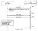
FIG. 1 is an example illustrating a threshold value for modifying the burst profile. The MS measures a Signal to Noise Ratio (SINR), for example, C/(N+1), and compares an average value of allowed application scope. The application scope is limited by a threshold level. That is, if the SINR exceeds the allowed application scope, the MS uses a DBPC scheme to request for a new burst profile. Based on whether the MS requests for a more robust profile having stronger interference (e.g., Quadrature Phase Shift Keying) or whether the MS requests for a less robust profile, having less interference (e.g., 64 Quadrature Amplitude Modulation), the BS executes transmission and reception of the message for actual change of the modulation scheme. Here, the term ‘more robust’ means that there is stronger interference, and the term ‘less robust’ means that there is less interference.
According to conventional art, if there is a plurality of code types which can be supported by MS within the scope of services available by the BS, and if downlink/uplink burst profiles are used to support various code types, the intervals (or space) of the SNR corresponding to each AMC increases. Therefore, a modulation scheme that can be provided for one coding type decreases. As a result, the intervals of the threshold values, used for changing the AMC per each coding type, increase, and consequently, there is a problem in properly applying the AMC according to the channel status.
SUMMARY OF THE INVENTIONAccordingly, the present invention is directed to a method of supporting multiple code types in a wireless mobile communication system that substantially obviates one or more problems due to limitations and disadvantages of the related art.
An object of the present invention is to provide a method of supporting multiple code types in a wireless mobile communication system.
Additional advantages, objects, and features of the invention will be set forth in part in the description which follows and in part will become apparent to those having ordinary skill in the art upon examination of the following or may be learned from practice of the invention. The objectives and other advantages of the invention may be realized and attained by the structure particularly pointed out in the written description and claims hereof as well as the appended drawings.
To achieve these objects and other advantages and in accordance with the purpose of the invention, as embodied and broadly described herein, [a method of supporting multiple code types in a wireless mobile communication system includes a mobile station (MS) which receives a channel descriptor from a base station (BS), wherein the channel descriptor includes at least one burst profile which includes a code type and an interval usage code. Thereafter, the MS, first, recognizes the code type which includes information on coding scheme to be used by the BS or the MS, and recognizes, second, an interval usage code which is used for classifying all data bursts.
In another aspect of the present invention, the MS receives a downlink channel descriptor (DCD) from a base station (BS), wherein the DCD includes at least one burst profile. After the receipt, the MS recognizes a code type which includes information on coding scheme to be used by the BS and an interval usage code which is used for classifying all data bursts.
Yet, in another aspect of the present invention, the MS receives an uplink channel descriptor (UCD) from a mobile station (MS), wherein the UCD includes at least one burst profile. After the receipt, the MS recognizes a code type which includes information on coding scheme to be used by the BS and an interval usage code which is used for classifying all data bursts.
In further aspect of the present invention, the MS receives a channel descriptor from a base station (BS), wherein the channel descriptor includes at least one burst profile set which includes a plurality of burst profiles which further includes an interval usage code and at least one code type. Thereafter, the MS recognizes, first, the at least one code type which includes information on coding schemes to be used by the BS or the MS, and recognizes, second, an interval usage code which is used for classifying all data bursts.
It is to be understood that both the foregoing general description and the following detailed description of the present invention are exemplary and explanatory and are intended to provide further explanation of the invention as claimed.
BRIEF DESCRIPTION OF THE DRAWINGSThe accompanying drawings, which are included to provide a further understanding of the invention and are incorporated in and constitute a part of this application, illustrate embodiment(s) of the invention and together with the description serve to explain the principle of the invention. In the drawings;
FIG. 1 is an example illustrating a threshold value for modifying the burst profile;
FIG. 2 is an exemplary diagram illustrating mapping of AMC to a DIUC according to a coding type;
FIG. 3 is an exemplary diagram illustrating mapping of the AMC to DIUC according to a coding type;
FIG. 4 illustrates an example of a method of applying burst profile; and
FIG. 5 illustrates an example of a method of applying another burst profile.
DETAILED DESCRIPTION OF THE INVENTIONReference will now be made in detail to the preferred embodiments of the present invention, examples of which are illustrated in the accompanying drawings. Wherever possible, the same reference numbers will be used throughout the drawings to refer to the same or like parts.
Table 1 is an example of the DCD message.
| TABLE 1 | ||
| Syntax | Size | Notes |
| DCD_Message_Format( ) { | ||
| Management Message | 8 bits | |
| Type = 1 | ||
| Downlink channel ID | 8 bits | |
| Configuration Change | 8 bits | |
| Count | ||
| TLV Encoded information | variable | TLV specific |
| for the overall channel | ||
| Begin PHY Specific Section | See applicable PHY section. | |
| { | ||
| for(i= 1; i <= n; i++) { | For each Downlink burst profile | |
| 1 to n. | ||
| Downlink_Burst_Profile | variable | PHY specific |
| } | ||
| } | ||
| } | ||
Table 2 is an example of the UCD message.
| TABLE 2 | ||
| Syntax | Size | Notes |
| UCD_Message_Format( ) { | ||
| Management Message Type = 0 | 8 bits | |
| Configuration Change Count | 8 bits | |
| Ranging Backoff Start | 8 bits | |
| Ranging Backoff End | 8 bits | |
| Request Backoff Start | 8 bits | |
| Request Backoff End | 8 bits | |
| TLV Encoded information for | variable | TLV specific |
| the overall channel | ||
| Begin PHY Specific Section { | See applicable PHY section. | |
| for(i= 1; i <= n; i++) { | For each uplink burst profile 1 | |
| to n. | ||
| Uplink_Burst_Profile | variable | PHY specific |
| } | ||
| } | ||
| } | ||
The DCD/UCD messages each include physical layer parameters for uplink and downlink allocated burst interval. As examples of the physical layer parameters, there are a modulation type and Forward Error Correction (FEC) code types. In addition, parameters for the FEC code types can be represented by, for example, K and R values of a Reed-Solomon (RS) code.
The parameters are mapped to the DIUC included in a Downlink_Burst_Profile of the DCD message and the UIUC included in an Uplink_Burst_Profile of the UCD message. That is, the Downlink_Burst_Profile information, which is included in the DCD message, can use the DIUC to define certain characteristics of the physical layer used in a specific downlink burst.
Table 3 is an example of a Downlink_Burst_Profile TLV format.
| TABLE 3 | |||
| Syntax | Size | Notes | |
| Downlink_Burst_Profile{ | |||
| Type=1 | 8 bits | ||
| Length | 8 bits | ||
| Reserved | 4 bits | Shall be set zero | |
| DIUC | 4 bits | ||
| TLV encoded information | Variable | ||
| } | |||
As illustrated in Table 3, the downlink burst profile includes a DIUC having a length of 4 bits. Since the DIUC has a 4-bit length, 16 different information (e.g., coding and modulation schemes) can be represented. Moreover, the BS or the cell can select and allocate 13 burst profiles onto DIUC0-DIUC12, and the FEC type can be mapped to each DIUC. Thereafter, the BS announces the selected burst profiles through the DCD/UCD messages.
Alternatively, the uplink burst profile included in the UCD message can use the UIUC to define certain characteristics of the physical layer used in a specific uplink burst.
Table 4 is an example of an Uplink_Burst_Profile TLV format.
| TABLE 4 | |||
| Syntax | Size | Notes | |
| Uplink_Burst_Profile{ | |||
| Type=1 | 8 bits | ||
| Length | 8 bits | ||
| Reserved | 4 bits | Shall be set to zero | |
| UIUC | 4 bits | ||
| TLV encoded information | variable | ||
| } | |||
As illustrated in Table 4, the uplink burst profile includes an UIUC having a length of 4 bits. Since the UIUC has a 4-bit length, 16 different information (e.g., coding and modulation schemes) can be represented. Moreover, the BS or the cell can select and allocate 10 burst profiles onto UIUC0-UIUC10, and the FEC type can be mapped to each UIUC. Thereafter, the BS announces the selected burst profiles through the DCD/UCD messages.
Tables 5 and 6 are examples of downlink burst profiles in Type, Length, Value (TLV) format.
| TABLE 5 | |||
| Type | |||
| Name | (1 byte) | Length | Value (variable length) |
| FEC Code type | 150 | 1 | 0 = QPSK (CC) 1/2 |
| 1 = QPSK (CC) 3/4 | |||
| 2 = 16-QAM (CC) 1/2 | |||
| 3 = 16-QAM (CC) 3/4 | |||
| 4 = 64-QAM (CC) 2/3 | |||
| 5 = 64-QAM (CC) 3/4 | |||
| 6 = QPSK (BTC) 1/2 | |||
| 7 = QPSK (BTC) 3/4 or 2/3 | |||
| 8 = 16-QAM (BTC) 3/5 | |||
| 9 = 16-QAM (BTC) 4/5 | |||
| 10 = 64-QAM (BTC) 2/3 or 5/8 | |||
| 11 = 64-QAM (BTC) 5/6 or 4/5 | |||
| 12 = QPSK (CTC) 1/2 | |||
| 13 = QPSK (CTC) 2/3 | |||
| 14 = QPSK (CTC) 3/4 | |||
| 15 = 16-QAM (CTC) 1/2 | |||
| 16 = 16-QAM (CTC) 3/4 | |||
| 17 = 64-QAM (CTC) 2/3 | |||
| 18 = 64-QAM (CTC) 3/4 | |||
| 19 = 64-QAM (CTC) 5/6 | |||
| 20 = QPSK (ZT CC) 1/2 | |||
| 21 = QPSK (ZT CC) 3/4 | |||
| 22 = 16-QAM (ZT CC) 1/2 | |||
| 23 = 16-QAM (ZT CC) 3/4 | |||
| 24 = 64-QAM (ZT CC) 2/3 | |||
| 25 = 64-QAM (ZT CC) 3/4 | |||
| 26 = QPSK (LDPC) 1/2 | |||
| 27 = QPSK (LDPC) 2/3 A code | |||
| 28 = QPSK (LDPC) 3/4 A code | |||
| 29 = 16-QAM (LDPC) 1/2 | |||
| 30 = 16-QAM (LDPC) 2/3 A code | |||
| 31 = 16-QAM (LDPC) 3/4 A code | |||
| 32 = 64-QAM (LDPC) 1/2 | |||
| 33 = 64-QAM (LDPC) 2/3 A code | |||
| 34 = 64-QAM (LDPC) 3/4 A code | |||
| 35 = QPSK (LDPC) 2/3 B code | |||
| 36 = QPSK (LDPC) 3/4 B code | |||
| 37 = 16-QAM (LDPC) 2/3 B code | |||
| 38 = 16-QAM (LDPC) 3/4 B code | |||
| 39 = 64-QAM (LDPC) 2/3 B code | |||
| 40 = 64-QAM (LDPC) 3/4 B code | |||
| 41. . . 255 = Reserved | |||
| TABLE 6 | |||
| DIUC Mandatory | 151 | 1 | 0-63.75 dB |
| exit | CINR at or below where this DIUC can | ||
| threshold | no longer be used and where this | ||
| change to a more robust DIUC is required, | |||
| in 0.25 dB units. See FIG. 81. | |||
| DIUC Minimum | 152 | 1 | 0-63.75 dB |
| entry threshold | The minimum CINR required to start | ||
| using this DIUC when changing from a | |||
| more robust DIUC is required, in 0.25 dB | |||
| units. See FIG. 81. | |||
Table 7 is an example of uplink burst profiles in Type, Length, Value (TLV) format.
| TABLE 7 | |||
| Name | Type | Length | Value |
| FEC Code type and | 150 | 1 | 0 = QPSK (CC) 1/2 |
| modulation type | 1 = QPSK (CC) 3/4 | ||
| 2 = 16-QAM (CC) 1/2 | |||
| 3 = 16-QAM (CC) 3/4 | |||
| 4 = 64-QAM (CC) 2/3 | |||
| 5 = 64-QAM (CC) 3/4 | |||
| 6 = QPSK (BTC) 1/2 | |||
| 7 = QPSK (BTC) 2/3 | |||
| 8 = 16-QAM (BTC) 3/5 | |||
| 9 = 16-QAM (BTC) 4/5 | |||
| 10 = 64-QAM (BTC) 5/8 | |||
| 11 = 64-QAM (BTC) 4/5 | |||
| 12 = QPSK (CTC) 1/2 | |||
| 13 = QPSK (CTC) 2/3 | |||
| 14 = QPSK (CTC) 3/4 | |||
| 15 = 16-QAM (CTC) 1/2 | |||
| 16 = 16-QAM (CTC) 3/4 | |||
| 17 = 64-QAM (CTC) 2/3 | |||
| 18 = 64-QAM (CTC) 3/4 | |||
| 19 = 64-QAM (CTC) 5/6 | |||
| 20 = QPSK (ZT CC) 1/2 | |||
| 21 = QPSK (ZT CC) 3/4 | |||
| 22 = 16-QAM (ZT CC) 1/2 | |||
| 23 = 16-QAM (ZT CC) 3/4 | |||
| 24 = 64-QAM (ZT CC) 2/3 | |||
| 25 = 64-QAM (ZT CC) 3/4 | |||
| 26 = QPSK (LDPC) 1/2 | |||
| 27 = QPSK (LDPC) 2/3 A code | |||
| 28 = QPSK (LDPC) 3/4 A code | |||
| 29 = 16-QAM (LDPC) 1/2 | |||
| 30 = 16-QAM (LDPC) 2/3 A code | |||
| 31 = 16-QAM (LDPC) 3/4 A code | |||
| 32 = 64-QAM (LDPC) 1/2 | |||
| 33 = 64-QAM (LDPC) 2/3 A code | |||
| 34 = 64-QAM (LDPC) 3/4 A code | |||
| 35 = QPSK (LDPC) 2/3 B code | |||
| 36 = QPSK (LDPC) 3/4 B code | |||
| 37 = 16-QAM (LDPC) 2/3 B code | |||
| 38 = 16-QAM (LDPC) 3/4 B code | |||
| 39 = 64-QAM (LDPC) 2/3 B code | |||
| 40 = 64-QAM (LDPC) 3/4 B code | |||
| 41 . . . 255 = Reserved | |||
| Normalized C/N for | 153 | 1 | This is a list of numbers where |
| UL ACK region and | each number is encoded by one | ||
| QPSK 1/3 | nibble and interpreted as a signed | ||
| integer The first LS nibble | |||
| corresponds to the C/N difference | |||
| of the UL ACK region comparing | |||
| to the CDMA code in Table 332. | |||
| The last nibble corresponds to | |||
| the C/N difference of the QPSK | |||
| 1/3 comparing to the CDMA | |||
| code in table 332. | |||
Using Table 3, the BS maps the FEC code types to 13 DIUCs (i.e., DIUC0-CIUC12) to configure the downlink burst profile. Mapping procedure includes negotiating available coding types by the MS using a Subscriber Station Basic Capability request and response (SBC-REQ/RSP) procedure.
Tables 8 and 9 are examples of modulation and demodulation schemes that can be supported by the MS.
| TABLE 8 | |||
| Type | Length | Value | Scope |
| 151 | Variable | Bit #0: 64-QAM | SBC-REQ (see 6.3.2.3.23) |
| Bit #1: BTC | SBC-RSP (see 6.3.2.3.24) | ||
| Bit #2: CTC | |||
| Bit #3: STC | |||
| Bit #4: AAS Diversity | |||
| Map Scan | |||
| Bit #5: HARQ | |||
| Chase | |||
| Bit #6: HARQ CTC IR | |||
| Bit #7: HARQ with | |||
| SPID = 0 only | |||
| Bit #8: HARQ CC IR | |||
| Bit #9: LDPC | |||
| Bit #10-15: Reserved: | |||
| shall be set to zero. | |||
| TABLE 9 | |||
| Type | Length | Value | Scope |
| 152 | Variable | Bit #0: 64-QAM | SBC-REQ (see 6.3.2.3.23) |
| Bit #1: BTC | SBC-RSP (see 6.3.2.3.24) | ||
| Bit #2: CTC | |||
| Bit #3: STC | |||
| Bit #4: AAS Diversity | |||
| Map Scan | |||
| Bit #5: HARQ Chase | |||
| Bit #6: HARQ CTC IR | |||
| Bit #7: HARQ with | |||
| SPID = 0 only. | |||
| Bit #8: HARQ CC IR | |||
| Bit #9: LDPC | |||
| Bit #10-15: Reserved: | |||
| shall be set to zero. | |||
| 153 | 1 | The number of HARQ | SBC-REQ (see 6.3.2.3.23) |
| ACK Channel. | SBC-RSP (see 6.3.2.3.24) | ||
With respect to the FEC code types, there are, to name a few, a Convolutional Code (CC), a Block Turbo Coding (BTC), a Convolutional Turbo Code (CTC), a Zero Tail Convolution Code (ZTTC), and Low Density Parity Code (LDPC). Among these FEC types, CC is considered mandatory while the other types are optional.
In operation, the BS always uses CC since its mandatory. Furthermore, since the DIUC can be mapped to 16 different information, CC is mapped to a maximum of 6 values of DIUC (e.g., DIUC0-DIUC5), and the remaining 6 values are selectively mapped by any one of BTC, CTC, ZTTC, and LDPC.
Even in case of the UIUC, mandatory CC is mapped to a maximum of 6 values (e.g., UIUC0-UIUC5) while the remaining 6 values are selectively mapped by any one of the BTC, CTC, ZTTC, and LDPC.
As an embodiment of the present invention, a method of generating a Burst Profile is introduced, the detail of which are as follows. First, each of the threshold values, represented in a TLV format, is mapped on one-to-one basis to each DIUC/UIUC value. The number of mapped values equals the number of DIUC/UIUC to be configured. Here, the threshold value is based on the FEC code type and the burst profile modification (or change) request. In addition, the burst profile includes information related to the coding type of the burst profile.
Table 10 is an example illustrating a downlink burst profile.
| TABLE 10 | |||
| Syntax | Size | Notes | |
| Type = 1 | 8 bits | ||
| Length | 8 bits | ||
| Reserved | 1 bits | Shall be set to zero | |
| Coding Type | 3 bits | 000: reserved | |
| 001: CC | |||
| 010: BTC | |||
| 011: CTC | |||
| 100: ZT CC | |||
| 101: LDPC A | |||
| 110: LDPC B | |||
| 111: reserved | |||
| DIUC | 4 bits | ||
| TLV encoded information | Variable | ||
Table 11 is an example illustrating an uplink burst profile.
| TABLE 11 | |||
| Syntax | Size | Notes | |
| Type = 1 | 8 bits | ||
| Length | 8 bits | ||
| Reserved | 1 bits | Shall be set to zero | |
| Coding Type | 3 bits | 000: reserved | |
| 001: CC | |||
| 010: BTC | |||
| 011: CTC | |||
| 100: ZT CC | |||
| 101: LDPC A | |||
| 110: LDPC B | |||
| 111: reserved | |||
| UIUC | 4 bits | ||
| TLV encoded information | Variable | ||
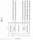
FIG. 2 is an exemplary diagram illustrating mapping of AMC to a DIUC according to a coding type. From various available coding types, the BS uses CC as default or put differently, the CC type is always used (i.e., mandatory CC). As such, DIUC for mandatory CC can be referred to as Downlink_Burst_Profile with type=1. As illustrated in FIG. 2, mandatory CC is mapped or allocated to DIUC0-DIUC5 and UIUC0-DIUC6 (21). That is, as shown in Table 10, for example, the ‘Coding Type’ field can be set as ‘001,’which represent mandatory CC, and the AMC can be mapped to each of 6 DIUC/UIUCs.
Furthermore, in order to allocate different coding types to remaining DIUCs, the BS allocates different coding types to DIUC6-CIUC12. Here, the coding type(s) allocated to DIUC6-DIUC12 are different from the coding type (i.e., CC) allocated to DIUC0-CIUC5. For example, if the BS decides to use BTC in addition to mandatory CC, the ‘Coding Type’ field is set to ‘010’, which represent BTC as indicated in Table 10, and the AMC is mapped to DIUC6-CIUC12 (22). Alternatively, if the BS supports CTC or LDPC, the ‘Coding Type Set’ field can be set to ‘011’ or ‘101, ’ respectively, and the AMC is mapped to each set of DIUC6-DIUC12 (23, 24).
Table 12 is another example of a downlink burst profile.
| TABLE 12 | |||
| Syntax | Size | Notes | |
| Type = 1 | 8 bits | ||
| Length | 8 bits | ||
| Reserved | 1 bits | Shall be set to zero | |
| Code type set | 3 bits | 000: reserved | |
| 001: CC + BTC | |||
| 010: CC + CTC | |||
| 011: CC + ZT CC | |||
| 100: CC + LDPC A | |||
| 101: CC + LDPC B | |||
| 110˜111: reserved | |||
| DIUC | 4 bits | ||
| TLV encoded information | Variable | ||
Table 13 is another example of an uplink burst profile.
| TABLE 13 | |||
| Syntax | Size | Notes | |
| Type = 1 | 8 bits | ||
| Length | 8 bits | ||
| Reserved | 1 bits | Shall be set to zero | |
| Code type set | 3 bits | 000: reserved | |
| 001: CC + BTC | |||
| 010: CC + CTC | |||
| 011: CC + ZT CC | |||
| 100: CC + LDPC A | |||
| 101: CC + LDPC B | |||
| 110˜111: reserved | |||
| UIUC | 4 bits | ||
| TLV encoded information | Variable | ||
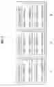
FIG. 3 is an exemplary diagram illustrating mapping of the AMC to DIUC according to a coding type. As illustrated in FIG. 3, a combination of each coding type can be used to configure a burst profile. Of many coding types, the BS allocates the mandatory CC. As such, the BS configures a ‘Code Type Set’ field according to coding types additionally supported by the BS. For example, if the BS supports BTC in addition to, of course, mandatory CC, the ‘Code Type Set’ field is set to ‘001.’ Under this setting, mandatory CC is allocated to DIUC0-DIUC5 and UIUC1-DIUC6 while BTC is allocated to DIUC6-DIUC12 (31).
Alternatively, if the BS supports CTC in addition to mandatory CC, the ‘Code Type Set’ field is set to ‘010,’ the mandatory CC is allocated to DIUC0-DIUC5 and UIUC1-DIUC6 while CTC is allocated to DIUC6-DIUC12 (32).
Alternatively, if the BS supports LDPC in addition to mandatory CC, the ‘Code Type Set’ field is set to ‘100,’ the mandatory CC is allocated to DIUC0-DIUC5 and UIUC1-DIUC6 while LDPC is allocated to DIUC6-DIUC12 (33).
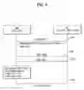
FIG. 4 illustrates an example of a method of applying burst profile. As illustrated in FIG. 4, the MS receives the burst profile, generated based on each coding types, via the DCD/UCD message (S41). Thereafter, the MS and the BS use the SBC-REQ/RSP process to negotiate the coding types that can be respectively supported (S42, S43). After receiving the SBC-RSP message from the BS, the MS interprets the DIUC value which corresponds to the ‘Coding Type’ or the ‘Code Type Set’ that can be supported by the MS.
After receiving the Burst Profile via the DCD/UCD message and negotiating with the BS the coding types that can be supported, if the coding type is determined (e.g., LDPC type), then the AMC, representing CC and LDPC types, is applied to the specific burst allocated to the MS, and the MS receives the downlink signal based on the AMC (S44).
Alternatively, it is possible to use the IE of the DL-MAP/UL-MAP to provide the MS, currently using a specific coding type, with a new coding type. When a new coding type is added via the expanded DIUC/UIUC, a new FEC code type can be provided to all MSs via the expanded DIUC.
FIG. 5 illustrates an example of a method of applying another burst profile. As illustrated in FIG. 5, the MS supports one default coding type and two newly added enhanced coding types. The MS uses the SBC-REQ message to report the coding types that can be supported by the MS (S51). In response, the BS uses the SBC-RSP message to notify the MS of which newly added enhanced coding types the BS intends to support (S52). In order to apply DIUC/UIUC, the MS recognizes the DIUC/UIUC values of the burst profile included in the DCD transmitted by the BS with the coding type allocated by the BS.
As illustrated in FIG. 5, the MS uses at least one of CC, CTC, and LDPC coding types. For example, if the MS uses mandatory CC and at the same time, CTC and LDPC can be supported, the MS reports the availability of these two coding types (e.g., CTC or LDPC) to the BS via the SBC-REQ message. Upon receipt, the BS selects one of the two coding types (i.e., LDPC) and transmits the selection via the SBC-RSP message to the MS. Thereafter, the MS recognizes the DIUC/UIUC values according to the LDPC.
Furthermore, a ‘Type’ field included in the DCD/UCD can be used to distinguish types of information necessary for the MS. For example, as illustrated in Tables 3 and 4, the ‘Type’ field is set to ‘1.’ Conventionally, the ‘Type’ field is used to determine the burst profile. As described above, the burst profile includes using at least one coding type, including a default coding type, while configuring the ‘Type’ field to ‘1.’ Moreover, the burst profile using a new coding type can be used to notify of a new coding type.
Table 14 is another example illustrating a downlink burst profile. Here, Table 14 defines the format of the Downlink_Burst_Profile with Type=153, which is used in the DCD message for the MS only. The DIUC field is associated with the Downlink_Burst_Profile and Thresholds. The DIUC value is used in the DL-MAP message to specify the burst profile to be used for a specific downlink burst.
| TABLE 14 | |||
| Syntax | Size | Notes | |
| Downlink burst profile{ | |||
| Type = 153 | 8 bits | ||
| Length | 8 bits | ||
| Reserved | 2 bits | Shall be set to zero | |
| Coding Type | 2 bits | 00: BTC | |
| 01: CTC | |||
| 10: ZT CC | |||
| 11: LDPC | |||
| DIUC | 4 bits | ||
| TLV encoded information | Variable | ||
| } | |||
Similarly to when the ‘Type’ field is set to ‘1,’ here, the ‘Type’ field is set to ‘153’ in the burst profile. The MS uses the burst profile having the ‘Type’ field set to ‘1’ to learn (or receive information) of the AMC level mapping of at least one coding type (i.e., CC). If the MS receives the burst profile having the ‘Type’ set to ‘153,’ the MS can only select the coding type(s) retained by the MS.
Table 15 is another example of an uplink burst profile.
| TABLE 15 | |||
| Syntax | Size | Notes | |
| Uplink burst profile{ | |||
| Type = 13 | 8 bits | ||
| Length | 8 bits | ||
| Reserved | 2 bits | Shall be set to zero | |
| Coding Type | 2 bits | 00: BTC | |
| 01: CTC | |||
| 10: ZT CC | |||
| 11: LDPC | |||
| UIUC | 4 bits | ||
| TLV encoded information | Variable | ||
| } | |||
Table 16 is an example illustrating the values of a UCD.
| TABLE 16 | ||||
| Type | Length | Value | PHY | |
| Name | (1 byte) | (1 byte) | (variable-length) | scope |
| . . . | . . . | . . . | . . . | . . . |
| Bandwidth_request_backoffb_start | 11 | 1 | Initial backoff window size | OFDMA |
| for contention | ||||
| BW requests, expressed as a | ||||
| power of 2. | ||||
| Values of n range 0-15 (the | ||||
| highest order | ||||
| bits shall be unused and set to 0 | ||||
| Bandwidth_request_backofff_start | 12 | 1 | Final backoff window size for | OFDMA |
| contention | ||||
| BW requests, expressed as a | ||||
| power of 2. | ||||
| Values of n range 0-15 (the | ||||
| highest order | ||||
| bits shall be unused and set to | ||||
| Uplink_burst_profile | 13 | 1 | May appear more than once | OFDMA |
| (see 6.3.2.3.3 and 8.4.5.5). | ||||
| The length is the number of | ||||
| bytes in the overall object, | ||||
| including embedded TLV | ||||
| items. | ||||
Table 17 is an example illustrating the values included in a DCD.
| TABLE 17 | ||||
| Type | Length | Value | PHY | |
| Name | (1 byte) | (1 byte) | (variable-length) | scope |
| . . . | . . . | . . . | . . . | . . . |
| Time-to-Trigger | 52 | 1 | Time-to-Trigger duration is | OFDMA |
| duration | the time duration for MS | |||
| decides to select a neighbor | ||||
| BS as a possible target BS. It | ||||
| is the unit of ms and | ||||
| applicable only for HHO. | ||||
| MAC version | 148 | 1 | See 11.1.3 | OFDMA |
| Downlink_burst_profile | 153 | 1 | May appear more than once | OFDMA |
| (see 6.3.2.3.1 and 8.4.5.5). | ||||
| The length is the number of | ||||
| bytes in the overall object, | ||||
| including embedded TLV | ||||
| items. | ||||
As illustrated in Tables 16 and 17, the value of the ‘Type’ field included in the DCD or UCD can be interpreted. Moreover, when the value of the ‘Type’ field is defined, besides the Burst Profile indicating the value of the ‘Type’ field is set to ‘I,’ the DCD/UCD can be used to indicating the existence of a new Burst Profile.
It will be apparent to those skilled in the art that various modifications and variations can be made in the present invention without departing from the spirit or scope of the inventions. Thus, it is intended that the present invention covers the modifications and variations of this invention provided they come within the scope of the appended claims and their equivalents.
Claims
What is claimed is:1. A method of supporting multiple code types in a wireless mobile communication system, the method comprising:
receiving a channel descriptor from a base station (BS), wherein the channel descriptor includes at least one burst profile which includes a code type and an interval usage code;
recognizing, first, the code type which includes information on coding scheme to be used by the BS or a mobile station (MS); and
recognizing, second, an interval usage code which is used for classifying all data bursts.
2. The method of claim 1, wherein the channel descriptor is a Downlink Channel Descriptor (DCD).
3. The method of claim 2, wherein the DCD includes a Downlink Interval Usage Code (DIUC).
4. The method of claim 1, wherein the channel descriptor is an Uplink Channel Descriptor (UCD).
5. The method of claim 4, wherein the UCD includes an Uplink Interval Usage Code (UIUC).
6. The method of claim 1, wherein the code type is a Forward Error Correction (FEC) code type.
7. The method of claim 6, wherein the FEC code type includes at least one of Convolutional Coding (CC), Block Turbo Coding (BTC), Convolutional Turbo Code (CTC), Zero Tail Convolution Code (ZTTC), and Low Density Parity Code (LDPC).
8. The method of claim 1, wherein the interval usage code is a Downlink Interval Usage Code (DIUC).
9. The method of claim 1, wherein the interval usage code is an Uplink Interval Usage Code (UIUC).
10. The method of claim 1, wherein the at least one burst profile is classified into at least two groups, a first group includes the interval usage codes and the code types having more than one coding scheme, and a second group includes the interval usage codes and a single code type.
11. The method of claim 10, further comprising a third group including the interval usage codes and a single code type, wherein the single code of the third group is different from the single code of the second group.
12. A method of supporting multiple code types in a wireless mobile communication system, the method comprising:
receiving a downlink channel descriptor (DCD) from a base station (BS), wherein the DCD includes at least one burst profile;
recognizing a code type which includes information on coding scheme to be used by the BS; and
recognizing an interval usage code which is used for classifying all data bursts.
13. The method of claim 12, wherein the burst profile includes a downlink interval usage code (DIUC).
14. The method of claim 12, wherein the burst profile includes a code type.
15. The method of claim 12, wherein the code type is a Forward Error Correction (FEC) code type.
16. The method of claim 15, wherein the FEC code type includes at least one of Convolutional Coding (CC), Block Turbo Coding (BTC), Convolutional Turbo Code (CTC), Zero Tail Convolution Code (ZTTC), and Low Density Parity Code (LDPC).
17. A method of supporting multiple code types in a wireless mobile communication system, the method comprising:
receiving an uplink channel descriptor (UCD) from a mobile station (MS), wherein the UCD includes at least one burst profile;
recognizing a code type which includes information on coding scheme to be used by the BS; and
recognizing an interval usage code which is used for classifying all data bursts.
18. The method of claim 17, wherein the burst profile includes a downlink interval usage code (DIUC).
19. The method of claim 17, wherein the burst profile includes a code type.
20. The method of claim 17, wherein the code type is a Forward Error Correction (FEC) code type.
21. The method of claim 20, wherein the FEC code type includes at least one of Convolutional Coding (CC), Block Turbo Coding (BTC), Convolutional Turbo Code (CTC), Zero Tail Convolution Code (ZTTC), and Low Density Parity Code (LDPC).
22. A method of supporting multiple code types in a wireless mobile communication system, the method comprising:
receiving a channel descriptor from a base station (BS), wherein the channel descriptor includes at least one burst profile set which includes a plurality of burst profiles which further includes an interval usage code and at least one code type;
recognizing, first, the at least one code type which includes information on coding schemes to be used by the BS or a mobile station (MS); and
recognizing, second, an interval usage code which is used for classifying all data bursts.
23. The method of claim 22, wherein a first group includes all available code types.
24. The method of claim 23, wherein a second group or a third group each includes one code type.
25. The method of claim 24, wherein a specified code type, included in the fist group, is shared by all the groups.
26. The method of claim 25, wherein the code type is a Forward Error Correction (FEC) code type.
Images & Drawings included:


Sources:
- United States Patent and Trademark Office - verify current appl. status at the USPTO↗
Recent applications in this class:
- » 20250293824 2025-09-18
DRIVE THROUGH AUDIO COMMUNICATION SYSTEM WITH MULTI-LANE SUPPORT - » 20250279862 2025-09-04
INFORMATION PROCESSING METHOD AND APPARATUS, AND TERMINAL DEVICE AND NETWORK DEVICE - » 20250253996 2025-08-07
BASE STATION, USER EQUIPMENT AND WIRELESS COMMUNICATION METHOD - » 20250233702 2025-07-17
METHOD AND APPARATUS FOR RECEIVING PPDU IN WIRELESS LAN SYSTEM - » 20250219776 2025-07-03
METHOD AND SYSTEM FOR JOINT-BAND HETEROGENOUS MULTI-ACCESS POINT COORDINATION - » 20250211385 2025-06-26
HYBRID AUTOMATIC REPEAT REQUEST (HARQ) DESIGNS FOR PROBABILISTIC AMPLITUDE SHAPING - » 20250158763 2025-05-15
SEMI-STATIC SWITCHING FOR DYNAMIC SUBCHANNEL OPERATION (DSO) - » 20250125920 2025-04-17
WIRELESS COMMUNICATION METHOD FOR SPEAKER DEVICES AND WIRELESS COMMUNICATION DEVICE THEREOF - » 20250015946 2025-01-09
PAYLOAD INDICATION FOR 802.11BN - » 20240380535 2024-11-14
AMBIENT POWER BACKSCATTER EXCITATION EXTENSION FOR PHYSICAL LAYER PROTOCOL DATA UNITS
Recent applications for this Assignee:
- » 20250294563 2025-09-18
METHOD AND DEVICE FOR INCREASING UPLINK CONTROL RESOURCES IN WIRELESS COMMUNICATION SYSTEM - » 20250294548 2025-09-18
METHOD AND DEVICE FOR TRANSMITTING/RECEIVING SIGNAL IN WIRELESS COMMUNICATION SYSTEM - » 20250294465 2025-09-18
METHOD AND APPARATUS FOR PERFORMING UPLINK TRANSMISSION IN WIRELESS COMMUNICATION SYSTEM - » 20250294425 2025-09-18
METHOD AND APPARATUS FOR MOBILITY BASED ON HEIGHT IN A WIRELESS COMMUNICATION SYSTEM - » 20250294206 2025-09-18
DISPLAY DEVICE AND CONTENT SHARING METHOD FOR SHARING CONTENT WITH EXTERNAL DISPLAY DEVICE - » 20250294153 2025-09-18
METHOD FOR CODING IMAGE ON BASIS OF SELECTIVE TRANSFORM AND DEVICE THEREFOR - » 20250294150 2025-09-18
METHOD AND APPARATUS FOR CABAC-BASED ENTROPY CODING - » 20250294136 2025-09-18
AFFINE MOTION PREDICTION-BASED IMAGE DECODING METHOD AND APPARATUS USING AFFINE MVP CANDIDATE LIST IN IMAGE CODING SYSTEM - » 20250292745 2025-09-18
SINK DEVICE AND OPERATING METHOD THEREOF - » 20250291418 2025-09-18
ELECTRONIC DEVICE HAVING TOUCH PAD REGION AND KEYBOARD