Method and circuit for detecting a brown out condition
US20060229830A1
2006-10-12
11/104,960
2005-04-12
✅ Patent granted
US 7,693,669 B2
2010-04-06
-
-
Hal D Wachsman
2026-03-21
Abstract:
A brown out detection circuit includes a sense amplifier for sensing a current level exhibited by a flash cell. Combinatorial logic is coupled to the sense amplifier for identifying a program condition of the flash cell based on the sensed current level, including a brown out condition, in order to provide a warning to avoid potential malfunction from a brown out condition.
Assignee:
- ATMEL CORPORATION 1,301 🇺🇸 San Jose, CA, United States
Interested in similar patents?
Get notified when new applications in this technology area are published.
Classification:
G11C16/3418 » CPC main
Erasable programmable read-only memories electrically programmable; Auxiliary circuits, e.g. for writing into memory; Determination of programming status, e.g. threshold voltage, overprogramming or underprogramming, retention Disturbance prevention or evaluation; Refreshing of disturbed memory data
G11C5/143 » CPC further
Details of stores covered by group; Power supply arrangements, e.g. power down, chip selection or deselection, layout of wirings or power grids, or multiple supply levels Detection of memory cassette insertion or removal; Continuity checks of supply or ground lines; Detection of supply variations, interruptions or levels ; Switching between alternative supplies
G11C16/30 » CPC further
Erasable programmable read-only memories electrically programmable; Auxiliary circuits, e.g. for writing into memory Power supply circuits
G11C29/50004 » CPC further
Checking stores for correct operation ; Subsequent repair ; Testing stores during standby or offline operation; Detection or location of defective memory elements, e.g. cell constructio details, timing of test signals; Marginal testing, e.g. race, voltage or current testing of threshold voltage
H03K17/223 » CPC further
Electronic switching or gating, i.e. not by contact-making and –breaking; Modifications for ensuring a predetermined initial state when the supply voltage has been applied in field-effect transistor switches
G11C16/04 » CPC further
Erasable programmable read-only memories electrically programmable using variable threshold transistors, e.g. FAMOS
G11C29/50 » CPC further
Checking stores for correct operation ; Subsequent repair ; Testing stores during standby or offline operation; Detection or location of defective memory elements, e.g. cell constructio details, timing of test signals Marginal testing, e.g. race, voltage or current testing
G01R19/00 IPC
Arrangements for measuring currents or voltages or for indicating presence or sign thereof
G06F11/30 IPC
Error detection; Error correction; Monitoring Monitoring
G01R31/00 IPC
Arrangements for testing electric properties; Arrangements for locating electric faults; Arrangements for electrical testing characterised by what is being tested not provided for elsewhere
Description
FIELD OF THE INVENTIONThe present invention relates to brown out detection systems.
BACKGROUND OF THE INVENTIONRecent advances in technology have led to an increase in performance and a decrease in size of semiconductor microcontroller or microprocessor chips. Microcontrollers generally receive power from a supply voltage that is external to the microcontroller. In order to ensure proper operation, many conventional microcontrollers employ a brown out detection system.
Brown out detection systems typically detect when a supply voltage level drops below a minimum level that is necessary for proper operation of the microcontroller and/or the item using the microcontroller. Brown out detection systems help protect the microcontroller against total power failure and against “dips” in the received voltage signal.
The ability to help protect a microcontroller and maintain proper functioning is widely beneficial, but of particular importance in critical application environments, including medical environments. A need exists for a brown out detection system that is straightforward, efficient, and effective. The present invention addresses such a need.
BRIEF SUMMARY OF THE INVENTIONAspects of brown out detection are described. Included in these aspects is a brown out detection circuit. The brown out detection circuit includes a sense amplifier for sensing a current level exhibited by a flash cell. Combinatorial logic is coupled to the sense amplifier for identifying a program condition of the flash cell based on the sensed current level, including a brown out condition, in order to provide a warning to avoid potential malfunction from a brown out condition.
Through the present invention, the program state of flash memory is employed in providing brown out detection. In a straightforward and efficient manner, the present invention provides detector circuitry that monitors for a drop in a current level of a programmed flash memory cell in order to identify a brown out condition. Potential malfunction can be avoided by use of the warning signal to allow for reprogramming or shut down of a controller. These and other advantages of the present invention will be more fully understood in conjunction with the following detailed description and accompanying drawings.
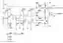
BRIEF DESCRIPTION OF SEVERAL VIEWS OF THE DRAWINGSFIG. 1 illustrates a circuit diagram of an example embodiment of a brown out detector in accordance with the present invention.
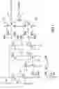
FIG. 2 illustrates an example simulation of operation of the circuit of FIG. 1 in accordance with the present invention.
DETAILED DESCRIPTION OF THE INVENTIONThe present invention is related to brown out detection systems. The following description is presented to enable one of ordinary skill in the art to make and use the invention and is provided in the context of a patent application and its requirements. Various modifications to the preferred embodiment and the generic principles and features described herein will be readily apparent to those skilled in the art. Thus, the present invention is not intended to be limited to the embodiments shown but is to be accorded the widest scope consistent with the principles and features described herein.
In accordance with the present invention, the program state of flash memory is employed in providing brown out detection. As is well understood in the art, flash memory is a type of EEPROM that can be erased and reprogrammed in blocks. Many modem PCs have their BIOS stored on a flash memory chip so that it can easily be updated if necessary. A typical flash memory comprises a memory array which includes a large number of memory cells arranged in row and column fashion. Each of the memory cells includes a floating gate field-effect transistor capable of holding a charge. The cells are usually grouped into blocks. Each of the cells within a block can be electrically programmed in a random basis by charging the floating gate. The charge can be removed from the floating gate by a block erase operation. The data in a cell is determined by the presence or absence of the charge in the floating gate.
In accordance with the present invention, the data in a flash cell is utilized in providing brown out detection. FIG. 1 illustrates a circuit diagram of a transimpedance sense amplifier to demonstrate providing brown out detection with a flash cell in accordance with the present invention. As shown, the circuit includes an amplifier 100 comprising transistors 102 and 104. Coupled to the amplifier 100 is a current comparator 106 comprising transistors 108 and 110. Also coupled to the amplifier is a flash cell represented by a current source 112. The data from the current comparator 106 is sampled and held by a latch 114. Inverter 116 buffers the output from the latch 114 to provide a DATA_OUT signal.
A second current comparator 118, comprising transistors 120 and 122, is coupled to the amplifier 100. A latch 124 is coupled to comparator 118. Combinatorial logic 126 in the form of an XOR gate is coupled to the latch 124 and outputs a signal (WARNING) as a brown out detection output.
In operation, when the current of current source 112 is low for an unprogrammed cell, the DATA_OUT will be low. When the current is high for a programmed cell, the DATA_OUT will be high. In detecting a brown out condition, the maintenance of the charge on a flash cell is monitored by monitoring the current seen. When a flash cell starts to lose its charge, the current will drop. If the current drops below a predetermined threshold (e.g., if the current drops below about 80% of a maximum value), the WARNING signal is output based on the combination through XOR gate 126 of the sampled states of current comparators 106 and 118 latched by latches 114 and 124.
In this manner, the brown out detector senses when the flash cells start to lose their contents. This may happen, for example, if the flash memory is subjected to high temperature over an extended period of time, subjected to radiation, etc. However, it will also detect when the cell current is too low, which will happen at low voltage supplies, or even when the clock frequency of the chip is too high (and the flash memory has not got enough time to resolve correct data). Thus, for critical applications (such as medical, for example), the warning signal can be used to prompt a controller to reprogram itself or completely shutdown to prevent malfunction, as is well appreciated by those skilled in the art.
FIG. 2 illustrates a signal diagram from a simulation of operation of the circuit of FIG. 1. It should be appreciated that this simulation reflects a loss of charge in the cell. Similar simulations give a brown out indication if the supply voltage drops or the clock frequency is too high.
Referring to FIG. 2, signal line 200 represents current levels of a flash cell (i(ieecell)). Signal line 202 represents voltage levels of the sample signal (v(sample)). The data output from latch 114 and buffered through inverter 116 is represented as voltage levels by signal line 204 (v(data_out)). Signal line 206 represents voltage levels of the warning signal (v(warning)) output from combinatorial logic 126. Three program conditions of the flash cell are represented in the signal lines. Namely, an unprogrammed cell condition is present at 0.5 us (microseconds), a good programmed flash cell is present at 2.5 us, and a slightly discharged programmed cell (brown out) condition is present at 4.5 us. As shown, the warning signal goes high in correspondence with the drop in current from the flash cell, indicative of a loss of charge in the cell and thus a drop in the supply voltage.
Although the present invention has been described in accordance with the embodiments shown, one of ordinary skill in the art will readily recognize that there could be variations to the embodiments and those variations would be within the spirit and scope of the present invention. Accordingly, many modifications may be made by one of ordinary skill in the art without departing from the spirit and scope of the appended claims.
Claims
We claim:1. A brown out detection circuit comprising:
a sense amplifier for sensing a current level exhibited by a flash cell; and
combinatorial logic coupled to the sense amplifier for identifying a program condition of the flash cell based on the sensed current level, including a brown out condition, in order to provide a warning to avoid potential malfunction from the brown out condition.
2. The circuit of claim 1 wherein the combinatorial logic further identifies a drop in the sensed current level of the flash cell in a programmed state as the brown out condition.
3. The circuit of claim 2 further comprising first and second current comparators coupled to the sense amplifier and receiving the sensed current level.
4. The circuit of claim 3 further comprising a first latch coupled to the first current comparator and a second latch coupled to the second current comparator to latch outputs from the first and second current comparators.
5. The circuit of claim 4 wherein the combinatorial logic further comprises an XOR gate logically combining outputs from the first and second latch.
6. The circuit of claim 5 wherein the XOR gate output provides the warning as an output signal.
7. A method for detecting a brown out condition, the method comprising:
sensing a current level exhibited by a flash cell; and
identifying a program condition of the flash cell based on the sensed current level, including a brown out condition, in order to provide a warning to avoid potential malfunction from the brown out condition.
8. The method of claim 7 wherein the step of identifying further comprises identifying a drop in the sensed current level of the flash cell in a programmed state as the brown out condition.
9. The method of claim 8 further comprising comparing the sensed current level by first and second current comparator circuits.
10. The method of claim 9 further comprising latching outputs from the first and second current comparator circuits in first and second latch circuits.
11. The method of claim 10 further comprising logically combining outputs from the first and second latch circuits with an XOR gate.
12. The method of claim 11 further comprising providing the warning as an output signal from the XOR gate.
13. A brown out detection circuit comprising:
a current source providing a current level exhibited by a flash memory;
a sense amplifier coupled to the current source for sensing the current level;
current comparator circuitry coupled to the sense amplifier for comparing the sensed current level to a predetermined threshold; and
combinatorial logic coupled to the current comparator circuitry for identifying a brown out condition when the sensed current level drops below the predetermined threshold in order to provide a warning to avoid potential malfunction from the brown out condition.
14. The circuit of claim 13 wherein the comparator circuitry further comprising first and second current comparators.
15. The circuit of claim 14 further comprising a first latch coupled to the first current comparator and a second latch coupled to the second current comparator to latch outputs from the first and second current comparators.
16. The circuit of claim 15 wherein the combinatorial logic further comprises an XOR gate logically combining outputs from the first and second latch.
17. The circuit of claim 16 wherein the XOR gate output provides the warning as an output signal.
Images & Drawings included:
Sources:
- United States Patent and Trademark Office - verify current appl. status at the USPTO↗
Recent applications in this class:
- » 20250292844 2025-09-18
Validating Uninitialized Usage-Based-Disturbance Data - » 20250279144 2025-09-04
DYNAMIC REFERENCE CORRECTIVE READ - » 20250273277 2025-08-28
MEMORY INCLUDING A PLURALITY OF PORTIONS AND USED FOR REDUCING PROGRAM DISTURBANCE AND PROGRAM METHOD THEREOF - » 20250266107 2025-08-21
STORAGE APPARATUS INCLUDING WORD LINE GROUPING DEVICE AND OPERATING METHOD THEREOF - » 20250232821 2025-07-17
THREE DIMENSIONAL MEMORY DEVICE - » 20250182831 2025-06-05
STORAGE DEVICE FOR PERFORMING REFRESH OPERATION AND OPERATING METHOD THEREOF - » 20250087278 2025-03-13
ELIMINATING WRITE DISTURB FOR SYSTEM METADATA IN A MEMORY SUB-SYSTEM - » 20250087277 2025-03-13
ALTERNATIVE ERASE SCHEMES FOR RELIABILITY-RISK WORD LINES - » 20250078939 2025-03-06
ENHANCED COMBINATION SCAN MANAGEMENT FOR BLOCK FAMILIES OF A MEMORY DEVICE - » 20250014654 2025-01-09
ADAPTIVE TEMPERATURE COMPENSATION FOR A MEMORY DEVICE
Recent applications for this Assignee:
- » 20190049494 2019-02-14
Microcontroller including power supply monitoring - » 20190026241 2019-01-24
Peripheral interface circuit for serial memory - » 20180253169 2018-09-06
Touch sensor with force sensor response normalization, and related method and apparatus - » 20180225452 2018-08-09
Input/output parameter selection - » 20180188699 2018-07-05
Autonomous process control peripheral - » 20180173669 2018-06-21
Serial device with configuration mode for changing device behavior - » 20180173657 2018-06-21
Automatic transmission of dummy bits in bus master - » 20180157443 2018-06-07
Microcontroller with integrated interface enabling reading data randomly from serial flash memory - » 20180089467 2018-03-29
Low cost cryptographic accelerator - » 20180068509 2018-03-08
Apparatus for locking and/or unlocking