Method and device for cooling vapor in a desorption column
US20060230932A1
2006-10-19
10/538,271
2003-08-06
✅ Patent granted
US 7,604,686 B2
2009-10-20
WO; PCT/EP03/08681; 20030806
WO; WO2004/052509; 20040624
Duane Smith | Ives Wu
2025-07-27
Abstract:
The invention relates to a method for cooling rising vapour (3) in a desorption column (2) by means of a condenser, which is situated at the head of the desorption column, is configured as an indirect heat exchanger and is traversed by a coolant (1). According to said method, the coolant enters at the bottom of the condenser (1) and flows upwards through conduits (8) that are arranged vertically in the condenser. The coolant is enriched with hydrogen sulphide prior to its entry into the condenser (1) and after the absorption of heat, escapes as an overflow (6) from the top of the condenser (1) through upper openings (10) of the conduits (8). The invention also relates to a desorption column (2) for carrying out said method.
Assignee:
- Uhde GmbH 162 🇩🇪 Dortmund, Germany
Interested in similar patents?
Get notified when new applications in this technology area are published.
Classification:
B01D53/14 IPC
Separation of gases or vapours; Recovering vapours of volatile solvents from gases; Chemical or biological purification of waste gases, e.g. engine exhaust gases, smoke, fumes, flue gases, aerosols, by absorption
B01D5/0012 » CPC main
Condensation of vapours; Recovering volatile solvents by condensation by using heat-exchange surfaces for indirect contact between gases or vapours and the cooling medium Vertical tubes
B01D5/0057 » CPC further
Condensation of vapours; Recovering volatile solvents by condensation in combination with other processes
F28B1/02 » CPC further
Condensers in which the steam or vapour is separate from the cooling medium by walls, e.g. surface condenser using water or other liquid as the cooling medium
F28F19/00 » CPC further
Preventing the formation of deposits or corrosion, e.g. by using filters or scrapers
Description
The invention relates to a method for cooling rising vapors in a desorption column by means of a condenser disposed at the head of the desorption column, configured as an indirect heat exchanger, through which a coolant flows, whereby the coolant enters into the condenser at the bottom and flows upward through vertical channels disposed in the condenser.
The head of a desorption column is usually equipped with a condenser that is operated with cooling water and is configured as an indirect heat exchanger. In the operation of an indirect heat exchanger, there is no direct contact between the fluid that absorbs the heat and the fluid that gives off the heat, since the fluids are separated from one another by means of flow guide elements, and the heat transport takes place through the flow guide elements. In the case of a load change of the desorption column, there is the risk that the cooling water temperature changes and that carbonate precipitation occurs. This is particularly the case if the cooling water temperature required for the desired operating state of the desorption column is high at the exit of the condenser. Carbonate precipitation at the heat transfer surfaces increasingly worsens the heat transfer behavior in the condenser and, in the final analysis, results in failure of the apparatus. This problem is circumvented in that the vapors are cooled by means of a direct heat exchange, e.g. sprinkling of the column head with cooling water. However, this direct heat exchange is difficult to regulate, because the cooling surface is not defined.
The invention is based on the task of indicating a method having the characteristics described initially, in which no carbonate precipitation occurs at the heat exchanger surfaces impacted by the cooling water, independent of the operating state of the desorption column. Furthermore, a good regulation possibility should exist in case of a load change.
According to the invention, this task is accomplished in that a coolant containing hydrogen sulfide is used, and that the coolant exits as an overflow, by means of top-side openings of the channels, at the top of the condenser, after the heat absorption has occurred. The cooling surface of the condenser is pre-determined by the heat exchanger surfaces. In the case of a load change of the desorption column, the temperature of the cooling surfaces can be adjusted very simply and precisely, by means of the cooling water amount. In this connection, deposition of carbonates on the heat exchanger surfaces can be effectively prevented by means of conducting the method in accordance with the invention, with the use of a coolant that contains hydrogen sulfide.
According to a preferred embodiment of the method according to the invention, the overflow flows into the desorption column. By means of applying a cooling water that contains hydrogen sulfide into the desorption column, the hydrogen sulfide is directly separated from the cooling water again after the heat transfer, since the hydrogen sulfide, which has a very low boiling point, leaves the desorption column at the head, together with the cooled vapors, while the water, which has a clearly lower boiling point, flows into the sump of the desorption column. Thus, no additional process step is necessary to remove the hydrogen sulfide from the cooling water again.
The object of the invention is also a desorption column according to claim 3, to implement the method.
In the following, the invention will be explained in detail, using a drawing that represents an embodiment merely as an example. The drawing shows:
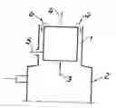
FIG. 1 a schematic representation of a condenser disposed at the head of a desorption column, and
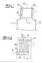
FIG. 2 a detailed representation of the condenser shown in FIG. 1.
FIG. 1 shows a condenser 1 that is disposed at the head of a desorption column 2. Vapors 3 rise from the desorption column, and are cooled by means of the condenser. The vapors 3 enter into the condenser 1 at the bottom. The non-condensing gases 4 that are cooled at heat exchanger surfaces of the condenser exit at the top of the condenser 1 and flow further upward. The cooling water 5, which has been enriched with hydrogen sulfide, according to the invention, enters into the condenser at the bottom. During the heat absorption, the cooling water 5 flows upward in the condenser and exits at the top of the condenser as an overflow 6. The overflow 6 flows into the desorption column 2.
FIG. 2 shows the structure of the condenser 1 according to the invention. The condenser 1 has a distributor device 7 as well as channels 8 that form heat exchanger surfaces, and is disposed in the column head of the desorption column 2. The cooling water 5 can flow through the distributor device 7; the latter serves to distribute the cooling water 5 that flows into the condenser 1. The distributor device 7 is rigidly connected with the channels 8 through which the fluid flows, which channels are disposed vertically. The sections 9 between the channels 8 are selected in such a manner that the rising vapors 3 can flow around the outside surfaces of the channels 8. The channels have top openings 10 from which the coolant exits.
Claims
1-3. (canceled)
4. Method for cooling rising vapors (3) in a desorption column (2) by means of a condenser (1) disposed at the head of the desorption column (2), configured as an indirect heat exchanger, through which cooling water flows, whereby the cooling water enters into the condenser (1) at the bottom and flows upward through vertical channels (8) disposed in the condenser (1), wherein cooling water containing hydrogen sulfide is used, wherein the cooling water exits as an overflow (6), by means of top-side openings (10) of the channels (8), at the top of the condenser (1), after the heat absorption has occurred, and wherein the overflow (6) flows into the desorption column (2).
5. Desorption column for carrying out the method according to claim 4, having a column head, a condenser (1) disposed therein, which has channels (8) through which cooling water flows, whereby the channels (8) are disposed vertically and flow can take place through them from the bottom to the top, and they form heat exchanger surfaces for cooling rising vapors, and whereby the channels (8) have top openings and thereby form an overflow (6) for the cooling water, which flows into the column (2).
Images & Drawings included:
Sources:
- United States Patent and Trademark Office - verify current appl. status at the USPTO↗
Recent applications in this class:
- » 20240092730 2024-03-21
THERMAL STRIPPING UREA PRODUCTION - » 20230041658 2023-02-09
A METHOD AND APPARATUS TO CONDENSE MAGNESIUM VAPOR USING A FLUID-COOLED HEAT EXCHANGER - » 20190262742 2019-08-29
Olefinic monomer recovery apparatus - » 20160317945 2016-11-03
ATMOSPHERIC WATER GENERATION SYSTEMS AND METHODS - » 20150265942 2015-09-24
Device and process for removing volatile organic and inorganic compounds from polluted waters - » 20120255712 2012-10-11
APPARATUS AND METHOD FOR CONDENSING VAPOR IN A VESSEL - » 20100319397 2010-12-23
CRYOGENIC PRE-CONDENSING METHOD AND APPARATUS
Recent applications for this Assignee:
- » 20140044601 2014-02-13
PROCESS FOR THE PURIFICATION OF CRUDE GAS FROM SOLIDS GASIFICATION - » 20130345486 2013-12-26
RECOVERY OF BENZENE AND BENZENE DERIVATIVES FROM GASOLINE FRACTIONS AND REFINERY STREAMS - » 20130248347 2013-09-26
Utilization of a coke oven featuring improved heating properties - » 20130228641 2013-09-05
Device for slag removal from a coal gasification reactor - » 20120160101 2012-06-28
Method for purifying gases and obtaining acid gases - » 20120149920 2012-06-14
Method for the production of a mixture of lactide derivatives - » 20120111416 2012-05-10
Method for supplying an entrained-flow gasification reactor with fuel from a storage container - » 20120067776 2012-03-22
Process for the recovery of pure aromatics from hydrocarbon fractions containing aromatics - » 20120060824 2012-03-15
METHOD AND APPARATUS FOR A CONSTANT STEAM GENERATION FROM THE WASTE HEAT OF AN ALKANE DEHYDROGENATION - » 20120058015 2012-03-08
Device for influencing the flow in a connecting pipe of a coal gasification reactor/gas cooler